EP0455003B1 - Vehicle control system - Google Patents
Vehicle control system Download PDFInfo
- Publication number
- EP0455003B1 EP0455003B1 EP91105442A EP91105442A EP0455003B1 EP 0455003 B1 EP0455003 B1 EP 0455003B1 EP 91105442 A EP91105442 A EP 91105442A EP 91105442 A EP91105442 A EP 91105442A EP 0455003 B1 EP0455003 B1 EP 0455003B1
- Authority
- EP
- European Patent Office
- Prior art keywords
- electronic
- vehicle
- block
- unit
- fact
- Prior art date
- Legal status (The legal status is an assumption and is not a legal conclusion. Google has not performed a legal analysis and makes no representation as to the accuracy of the status listed.)
- Expired - Lifetime
Links
- 239000000446 fuel Substances 0.000 description 4
- 238000012423 maintenance Methods 0.000 description 4
- 238000004519 manufacturing process Methods 0.000 description 4
- 238000009434 installation Methods 0.000 description 3
- 239000012809 cooling fluid Substances 0.000 description 2
- 230000001771 impaired effect Effects 0.000 description 2
- 238000002347 injection Methods 0.000 description 2
- 239000007924 injection Substances 0.000 description 2
- 230000005540 biological transmission Effects 0.000 description 1
- 238000010586 diagram Methods 0.000 description 1
- 230000005672 electromagnetic field Effects 0.000 description 1
- 238000012216 screening Methods 0.000 description 1
Images

Classifications
-
- B60K35/10—
-
- B—PERFORMING OPERATIONS; TRANSPORTING
- B60—VEHICLES IN GENERAL
- B60K—ARRANGEMENT OR MOUNTING OF PROPULSION UNITS OR OF TRANSMISSIONS IN VEHICLES; ARRANGEMENT OR MOUNTING OF PLURAL DIVERSE PRIME-MOVERS IN VEHICLES; AUXILIARY DRIVES FOR VEHICLES; INSTRUMENTATION OR DASHBOARDS FOR VEHICLES; ARRANGEMENTS IN CONNECTION WITH COOLING, AIR INTAKE, GAS EXHAUST OR FUEL SUPPLY OF PROPULSION UNITS IN VEHICLES
- B60K37/00—Dashboards
Definitions
- the present invention relates to an electronic control system for controlling motor vehicle members and equipment.
- Modern cars are known to feature a number of electronic and electromechanical systems, each controlling a respective part of the vehicle.
- some of these systems such as the ignition and electronic injection systems, are integrated as described in the article of Patrick D. Jordan published in Electronics and Wireless World and entitled “Advanced engine management systems", while, on others, they are connected over data transmission lines, as described in the Patent DE-A-3504181 and in the article of Dan McCosh published in Popular Science and entitled “Smart circuits revolutionize auto wiring”.
- a vehicle control system consisting of a number of systems presents numerous drawbacks.
- each electronic system features its own electronic control unit and sensors for detecting physical parameters and the operating status of given vehicle components, with the result that, invariably, the same parameter or component operating status is detected by more than one sensor, i.e. one for each control unit.
- a similar arrangement also involves the use of a large number of detecting members and electrical connections, and fails to make full use of certain parts of the electronic systems (e.g. the computing capacity of the control unit microprocessors) thus resulting in higher manufacturing and installation cost.
- a vehicle control system incorporating all the electronic equipment on the vehicle, comprising: a main electronic logic unit connected to the vehicle battery via a first electronic electrical supply block; a second electronic block indicating operating data and parameters, i.e.
- Number 1 in the accompanying drawings indicates an electronic vehicle control system installed inside the passenger compartment, in particular on the dashpanel, of the vehicle.
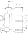
- System 1 comprises: a main logic unit 2 connected to the vehicle battery via an electrical supply block 3; a block 4 indicating operating data and parameters (the operating status of the engine and vehicle) and substantially representing the instrumentation on the vehicle; an interface block 5 to which are connected a number of sensors 6 designed, as described later, to detect data, parameters, operation and operating status relative to various vehicle members and components; an interface block 7 to which are connected a number of electromechanical controls 8; a block 11 for controlling electronic injectors 12; a block 13 for controlling a power module 14 of the electronic ignition system; and a block 15 for transmitting and receiving from unit 2 diagnostic data relative to the electronics of system 1, and consisting of a diagnostic tap 16 as shown in Fig.1.
- System 1 may feature additional optional blocks 17 for the purposes described later on.
- System 1 as described above therefore incorporates all the electronic equipment on the vehicle, which is controlled by one main unit requiring one sensor 6 for detecting each data item, parameter or vehicle component operating status.
- Sensors 6 are all electronic transducer types, which provide for numerous advantages (low cost, troublefree installation, low wear and substantially no maintenance) as compared with currently used mechanical transducers or detecting members in general.
- system 1 is installed on the dashpanel of the vehicle.
- system 1 consists of two housings 21 and 22 containing main unit 2 and blocks 3, 4, 5, 7, 11 and 13 connected to the same, and connected electrically by a line 23 (shown by the dotted line).
- Housing 21 presents a front panel 24 supporting block 4 and diagnostic tap 16.
- Block 4 comprises a number of indicators showing parameters and data relative to operation and the operating status of the vehicle engine and components.
- indicator 25 shows the speed per hour of the vehicle;
- indicator 26 the fuel level;
- indicator 27 the temperature of the engine cooling fluid;
- indicator 28 the pressure of the multistage centrifugal blower (if installed);
- indicator 31 the total mileage of the vehicle; and indicator 32 the partial mileage count.
- a button 33 is provided for resetting the partial mileage indicator, and which may be connected directly to block 4, as shown in Fig.2, or represented by one of electromechanical controls 8.
- Block 4 also comprises a number of indicator lights 34 for indicating the operating status of certain parts of the vehicle, such as the headlights or direction indicators.
- the indicators may of course provide for numerical and/or figurative display, wherein the parameter is shown, for example, in proportion to the overall extension of a light scale, as on a graduated scale.
- the electromechanical controls indicated herein by 8 are representative of both user-operated controls, for operating the lights, power window regulator, centralized door lock, seat and seatback regulator, windscreen wipers, etc., and main unit 2 control via block 7 of the actuators governing user-controlled operation of the vehicle members.
- Fig.2 shows direct electrical connecting lines from control 8 to block 7 and vice versa.
- Housing 22 presents a front panel 35 supporting a number of buttons 36 representing user-operated controls 8.
- the size of the dashpanel permitting provision may be made for one housing having a front panel fitted with all the components supported, in the example shown, on panels 24 and 35.
- block 5 is connected to a number of sensors 6 for detecting all the data processed and required by unit 2 for controlling the other blocks in system 1.
- the data normally detected substantially relates to engine cooling fluid temperature; air temperature and pressure in the intake manifold for mixing and atomising the fuel; engine speed and phase, which, together with the air intake data, provides for controlling electronic injection and ignition; fuel level in the tank, which, together with other data, provides for calculating fuel consumption; vehicle speed, which, together with other data, provides for calculating average traveling speed; oil level and temperature, etc..
- certain parameters may be calculated by processing the data supplied to unit 2 by sensors 6.
- the intake air temperature gives an approximate indication of the temperature outside the vehicle and, for example, the possibility of ice forming on the road surface, which may be shown by an alarm light or an additional all-purpose alarm indicator on block 4 for "dialoging" between system 1 and the user, e.g. for providing a fasten-seat-belt warning, or indicating speeding or an open door with the vehicle in motion.
- tap 16 need simply be connected to a known unit for indicating and/or displaying the data relative to the parts being controlled.
- System 1 is electronically and, therefore, physically compact, thus enabling it to be installed directly on the dashpanel inside the passenger compartment; presents fewer component parts (e.g. fewer sensors) enabling low-cost manufacture; and features a single main data processing unit employed to maximum capacity.
- location of system 1 safeguards the components and electrical connections from thermal and mechanical stress and electromagnetic interference normally present in the engine compartment. As such, system 1 provides for a high degree of reliability and requires no particular maintenance. Control of all the electronic equipment on the vehicle, during both vehicle assembly and routine maintenance, is simplified by diagnostic tap 16 being located in an easily accessible position inside the passenger compartment.
- system 1 may be provided with additional control blocks (blocks 17) for performing additional functions, or provision may be made for direct access to the data bus of unit 2 by a trip computer.
Description
- The present invention relates to an electronic control system for controlling motor vehicle members and equipment.
- Modern cars are known to feature a number of electronic and electromechanical systems, each controlling a respective part of the vehicle. On some cars, some of these systems, such as the ignition and electronic injection systems, are integrated as described in the article of Patrick D. Jordan published in Electronics and Wireless World and entitled "Advanced engine management systems", while, on others, they are connected over data transmission lines, as described in the Patent DE-A-3504181 and in the article of Dan McCosh published in Popular Science and entitled "Smart circuits revolutionize auto wiring".
- A vehicle control system consisting of a number of systems presents numerous drawbacks.
- Foremost of these in the fact each electronic system features its own electronic control unit and sensors for detecting physical parameters and the operating status of given vehicle components, with the result that, invariably, the same parameter or component operating status is detected by more than one sensor, i.e. one for each control unit. A similar arrangement also involves the use of a large number of detecting members and electrical connections, and fails to make full use of certain parts of the electronic systems (e.g. the computing capacity of the control unit microprocessors) thus resulting in higher manufacturing and installation cost. Moreover, some or part of the systems currently employed and part of the electrical connecting circuits are housed in the engine compartment, which invariably results in impaired mechanical efficiency of certain parts of the system, due to wear caused by the high temperature and vibration inside the engine compartment, and impaired electronic performance due to the presence of strong, high- and low-voltage pulsating current and electromagnetic fields. Additional cost is therefore incurred for screening and insulating the members and electrical circuits housed inside the engine compartment. A further point to note is that all or most of the instrumentation on the vehicle is electromechanical, which rules out not only the possibility of exploiting the other system sensors, but also the possibility of integrating the instrumentation with the other electronic systems. Lastly, but by no means less importantly, is the number and location of the diagnostic taps. Each electronic system is known to feature a diagnostic tap for controlling or calibrating the electronic equipment on the vehicle at the end of the production line or during routine maintenance of the vehicle. At present, the diagnostic taps are housed in poorly accessible locations inside the engine compartment.
- It is an object of the present invention to provide a vehicle control system designed to overcome the aforementioned drawbacks.
- According to the present invention, there is provided a vehicle control system incorporating all the electronic equipment on the vehicle, comprising:
a main electronic logic unit connected to the vehicle battery via a first electronic electrical supply block; a second electronic block indicating operating data and
parameters, i.e. the operating status of the engine and vehicle;
a third electronic interface block to which are connected a number of sensors for detecting data, parameters, operation and operating status relative to various vehicle members and components;
a fourth electronic interface block to which are connected a number of electromechanical controls representative of both user-operated controls and controls enabled by said unit and governing said vehicle members and components;
a fifth electronic block for controlling electronic injectors; and
a sixth electronic block for controlling an electronic ignition power module; said blocks being connected electrically by electric connection lines to said unit,
characterized in that said unit and said blocks are installed on the vehicle dashpanel
A preferred non-limiting embodiment of the present invention will be described by way of example with reference to the accompanying drawings, in which: - Fig.1 shows a view in perspective of a vehicle control system as installed inside the passenger compartment of the vehicle;
- Fig.2 shows an electronic block diagram of the Fig.1 system.
-
Number 1 in the accompanying drawings indicates an electronic vehicle control system installed inside the passenger compartment, in particular on the dashpanel, of the vehicle. -
System 1 comprises:
amain logic unit 2 connected to the vehicle battery via anelectrical supply block 3;
ablock 4 indicating operating data and parameters (the operating status of the engine and vehicle) and substantially representing the instrumentation on the vehicle;
aninterface block 5 to which are connected a number of sensors 6 designed, as described later, to detect data, parameters, operation and operating status relative to various vehicle members and components;
an interface block 7 to which are connected a number ofelectromechanical controls 8;
ablock 11 for controllingelectronic injectors 12;
ablock 13 for controlling apower module 14 of the electronic ignition system; and
ablock 15 for transmitting and receiving fromunit 2 diagnostic data relative to the electronics ofsystem 1, and consisting of adiagnostic tap 16 as shown in Fig.1. -
System 1 may feature additionaloptional blocks 17 for the purposes described later on. -
System 1 as described above therefore incorporates all the electronic equipment on the vehicle, which is controlled by one main unit requiring one sensor 6 for detecting each data item, parameter or vehicle component operating status. Sensors 6 are all electronic transducer types, which provide for numerous advantages (low cost, troublefree installation, low wear and substantially no maintenance) as compared with currently used mechanical transducers or detecting members in general. - Think, for example, of the advantage afforded by replacing current speed-per-hour detecting systems with an electronic pickup device. Moreover, certain parameters may be detected by simply processing those detected by certain sensors, thus reducing the actual number of sensors required.
- As already stated and shown in Fig.1,
system 1 is installed on the dashpanel of the vehicle. In the embodiment shown,system 1 consists of twohousings main unit 2 andblocks Housing 21 presents afront panel 24 supportingblock 4 anddiagnostic tap 16.Block 4 comprises a number of indicators showing parameters and data relative to operation and the operating status of the vehicle engine and components. In particular,indicator 25 shows the speed per hour of the vehicle;indicator 26 the fuel level;indicator 27 the temperature of the engine cooling fluid;indicator 28 the pressure of the multistage centrifugal blower (if installed);indicator 31 the total mileage of the vehicle; andindicator 32 the partial mileage count. To the side ofindicator 32, abutton 33 is provided for resetting the partial mileage indicator, and which may be connected directly toblock 4, as shown in Fig.2, or represented by one ofelectromechanical controls 8. -
Block 4 also comprises a number ofindicator lights 34 for indicating the operating status of certain parts of the vehicle, such as the headlights or direction indicators. The indicators may of course provide for numerical and/or figurative display, wherein the parameter is shown, for example, in proportion to the overall extension of a light scale, as on a graduated scale. - The electromechanical controls indicated herein by 8 are representative of both user-operated controls, for operating the lights, power window regulator, centralized door lock, seat and seatback regulator, windscreen wipers, etc., and
main unit 2 control via block 7 of the actuators governing user-controlled operation of the vehicle members. For this reason, Fig.2 shows direct electrical connecting lines fromcontrol 8 to block 7 and vice versa.Housing 22 presents afront panel 35 supporting a number ofbuttons 36 representing user-operatedcontrols 8. Obviously, the size of the dashpanel permitting, provision may be made for one housing having a front panel fitted with all the components supported, in the example shown, onpanels - As already stated,
block 5 is connected to a number of sensors 6 for detecting all the data processed and required byunit 2 for controlling the other blocks insystem 1. The data normally detected substantially relates to engine cooling fluid temperature; air temperature and pressure in the intake manifold for mixing and atomising the fuel; engine speed and phase, which, together with the air intake data, provides for controlling electronic injection and ignition; fuel level in the tank, which, together with other data, provides for calculating fuel consumption; vehicle speed, which, together with other data, provides for calculating average traveling speed; oil level and temperature, etc.. As already stated, certain parameters may be calculated by processing the data supplied tounit 2 by sensors 6. For example, the intake air temperature gives an approximate indication of the temperature outside the vehicle and, for example, the possibility of ice forming on the road surface, which may be shown by an alarm light or an additional all-purpose alarm indicator onblock 4 for "dialoging" betweensystem 1 and the user, e.g. for providing a fasten-seat-belt warning, or indicating speeding or an open door with the vehicle in motion. For diagnosing the electronic equipment,tap 16 need simply be connected to a known unit for indicating and/or displaying the data relative to the parts being controlled. - The advantages of the present invention invention will be clear from the foregoing description.
- In particular, it provides for a vehicle control system incorporating all the current systems, including the instrumentation which, as described, is fully electronic.
- Also, being electronic transducer types, the sensors employed provide for reducing manufacturing and assembly cost (by simplifying installation) and improving reliability (by eliminating mechanical wear).
System 1 is electronically and, therefore, physically compact, thus enabling it to be installed directly on the dashpanel inside the passenger compartment; presents fewer component parts (e.g. fewer sensors) enabling low-cost manufacture; and features a single main data processing unit employed to maximum capacity. Moreover, the location ofsystem 1 safeguards the components and electrical connections from thermal and mechanical stress and electromagnetic interference normally present in the engine compartment. As such,system 1 provides for a high degree of reliability and requires no particular maintenance. Control of all the electronic equipment on the vehicle, during both vehicle assembly and routine maintenance, is simplified bydiagnostic tap 16 being located in an easily accessible position inside the passenger compartment. - To those skilled in the art, it will be clear that changes may be made to
system 1 as described and illustrated herein without, however, departing from the scope of the present invention. - For example, as already stated,
system 1 may be provided with additional control blocks (blocks 17) for performing additional functions, or provision may be made for direct access to the data bus ofunit 2 by a trip computer.
Claims (5)
- A vehicle control system incorporating all the electronic equipment on the vehicle, comprising:
a main electronic logic unit (2) connected to the vehicle battery via a first electronic electrical supply block (3);
a second electronic block (4) indicating operating data and parameters, i.e. the operating status of the engine and vehicle;
a third electronic interface block (5) to which are connected a number of sensors (6) for detecting data, parameters, operation and operating status relative to various vehicle members and components;
a fourth electronic interface block (7) to which are connected a number of electromechanical controls (8) representative of both user-operated controls and controls enabled by said unit (2) and governing said vehicle members and components;
a fifth electronic block (11) for controlling electronic injectors (12); and
a sixth electronic block (13) for controlling an electronic ignition power module (14);
said blocks (3, 4, 5, 7, 11, 13) being connected by electric connection line to said unit (2),
characterized in that said unit (2) and said blocks (3, 4, 5, 7, 11, 13) are installed on the vehicle dashpanel. - A system as claimed in Claim 1, characterised by the fact that it comprises at least one housing (21 and/or 22) having a front panel (24 or 35) supporting a number of electronic indicators (25, 26, 27, 28, 31, 32) of said second block (4).
- A system as claimed in Claim 2, characterised by the fact that said panel (24) supports a number of indicator lights (34) for indicating alarm status, operation or operating status of parts of the vehicle, such as operation of the vehicle lights or direction indicators.
- A system as claimed in Claim 2 and/or 3, characterised by th e fact that said panel (35) supports said user-operated electromechanical controls (8).
- A system as claimed in at least one of the foregoing Claims from 2 to 4, characterised by the fact that it comprises a seventh electronic block (15) for transmitting and receiving data from said unit (2) and connected to a unit for diagnosing the electronics of said system; said seventh block (15) comprising a diagnostic tap (16) on said panel (24).
Applications Claiming Priority (2)
| Application Number | Priority Date | Filing Date | Title |
|---|---|---|---|
| IT67257A IT1240172B (en) | 1990-04-06 | 1990-04-06 | VEHICLE CONTROL SYSTEM |
| IT6725790 | 1990-04-06 |
Publications (2)
| Publication Number | Publication Date |
|---|---|
| EP0455003A1 EP0455003A1 (en) | 1991-11-06 |
| EP0455003B1 true EP0455003B1 (en) | 1994-11-30 |
Family
ID=11300911
Family Applications (1)
| Application Number | Title | Priority Date | Filing Date |
|---|---|---|---|
| EP91105442A Expired - Lifetime EP0455003B1 (en) | 1990-04-06 | 1991-04-05 | Vehicle control system |
Country Status (4)
| Country | Link |
|---|---|
| EP (1) | EP0455003B1 (en) |
| DE (1) | DE69105344T2 (en) |
| ES (1) | ES2067786T3 (en) |
| IT (1) | IT1240172B (en) |
Families Citing this family (3)
| Publication number | Priority date | Publication date | Assignee | Title |
|---|---|---|---|---|
| DE29624492U1 (en) * | 1996-07-27 | 2004-06-17 | Claas Kgaa Mbh | Control device e.g. for agricultural tractor setting element - has manual operating elements within tractor cab used for selection of automatic control sequence for setting element |
| DE102006004243A1 (en) * | 2006-01-30 | 2007-08-02 | Siemens Ag | Mount for vehicle cockpit has electrical devices and also ventilation device, with at least one air duct and outlet openings, mounted upon it, wherein mount can be installed in cockpit as preassembled, self-supporting module |
| CN113146510B (en) * | 2021-04-25 | 2022-09-27 | 山东交通职业学院 | Motorcycle tap adjusting device |
Family Cites Families (2)
| Publication number | Priority date | Publication date | Assignee | Title |
|---|---|---|---|---|
| US4493303A (en) * | 1983-04-04 | 1985-01-15 | Mack Trucks, Inc. | Engine control |
| JPH0737771B2 (en) * | 1984-02-07 | 1995-04-26 | 日産自動車株式会社 | Slot control device |
-
1990
- 1990-04-06 IT IT67257A patent/IT1240172B/en active IP Right Grant
-
1991
- 1991-04-05 ES ES91105442T patent/ES2067786T3/en not_active Expired - Lifetime
- 1991-04-05 DE DE69105344T patent/DE69105344T2/en not_active Expired - Fee Related
- 1991-04-05 EP EP91105442A patent/EP0455003B1/en not_active Expired - Lifetime
Non-Patent Citations (1)
| Title |
|---|
| Jurgen: "Coming from Detroit : networks on wheels" * |
Also Published As
| Publication number | Publication date |
|---|---|
| DE69105344T2 (en) | 1995-04-06 |
| IT9067257A0 (en) | 1990-04-06 |
| ES2067786T3 (en) | 1995-04-01 |
| DE69105344D1 (en) | 1995-01-12 |
| IT1240172B (en) | 1993-11-27 |
| EP0455003A1 (en) | 1991-11-06 |
| IT9067257A1 (en) | 1991-10-06 |
Similar Documents
| Publication | Publication Date | Title |
|---|---|---|
| US6107696A (en) | Circuitry for function modules which can be fitted in a motor vehicle | |
| US4542460A (en) | Driving aid indicator for economical operation of automatic transmission equipped motor vehicle | |
| US5121112A (en) | Display apparatus for vehicle | |
| SU912050A3 (en) | Device for controlling bulldozer operation | |
| CN101301872A (en) | Vehicle maintenance prompting system | |
| EP0554465B1 (en) | Control module assembly unit for mounting on vehicle | |
| US20090153316A1 (en) | Wireless wheel speed sensor | |
| WO2007053545A2 (en) | Vehicle odometer using on-board diagnostic information | |
| US7331531B2 (en) | Condensation sensor | |
| CN102536542A (en) | System for checking filter of air cleaner for automobiles | |
| EP0455003B1 (en) | Vehicle control system | |
| US6177878B1 (en) | Meter driving device | |
| GB2443655A (en) | A taximeter using a signal from a vehicle diagnostic system | |
| EP1403119B1 (en) | Fuel tank interface assembly | |
| CN102639364B (en) | Vehicle display device | |
| CN101393038A (en) | Instrument device for vehicle | |
| US20040030528A1 (en) | Device for inclination determination and arrangemet for the setting of a driver command | |
| CN108806281A (en) | Vehicle based on photovoltaic highway and vehicle speed signal processing system | |
| CN203657932U (en) | Frequency output type multifunctional sensor | |
| CN112373303B (en) | Display instrument with GPRS communication and alarm functions | |
| Jones | The challenge of automotive electronics in the USA | |
| JP3204357B2 (en) | Automotive wiring equipment | |
| JPH106811A (en) | Meter device for automobile | |
| WO2017093785A1 (en) | Low cost instrument cluster based hvac power control | |
| KR100366181B1 (en) | Device for measuring refrigerant water temperature of vehicle engine |
Legal Events
| Date | Code | Title | Description |
|---|---|---|---|
| PUAI | Public reference made under article 153(3) epc to a published international application that has entered the european phase |
Free format text: ORIGINAL CODE: 0009012 |
|
| AK | Designated contracting states |
Kind code of ref document: A1 Designated state(s): DE ES FR GB SE |
|
| 17P | Request for examination filed |
Effective date: 19920504 |
|
| 17Q | First examination report despatched |
Effective date: 19921113 |
|
| GRAA | (expected) grant |
Free format text: ORIGINAL CODE: 0009210 |
|
| AK | Designated contracting states |
Kind code of ref document: B1 Designated state(s): DE ES FR GB SE |
|
| REF | Corresponds to: |
Ref document number: 69105344 Country of ref document: DE Date of ref document: 19950112 |
|
| PG25 | Lapsed in a contracting state [announced via postgrant information from national office to epo] |
Ref country code: SE Effective date: 19950228 |
|
| ET | Fr: translation filed | ||
| REG | Reference to a national code |
Ref country code: ES Ref legal event code: FG2A Ref document number: 2067786 Country of ref document: ES Kind code of ref document: T3 |
|
| PLBE | No opposition filed within time limit |
Free format text: ORIGINAL CODE: 0009261 |
|
| STAA | Information on the status of an ep patent application or granted ep patent |
Free format text: STATUS: NO OPPOSITION FILED WITHIN TIME LIMIT |
|
| 26N | No opposition filed | ||
| PGFP | Annual fee paid to national office [announced via postgrant information from national office to epo] |
Ref country code: GB Payment date: 19980326 Year of fee payment: 8 |
|
| PGFP | Annual fee paid to national office [announced via postgrant information from national office to epo] |
Ref country code: FR Payment date: 19980327 Year of fee payment: 8 |
|
| PGFP | Annual fee paid to national office [announced via postgrant information from national office to epo] |
Ref country code: ES Payment date: 19980416 Year of fee payment: 8 |
|
| PGFP | Annual fee paid to national office [announced via postgrant information from national office to epo] |
Ref country code: DE Payment date: 19980624 Year of fee payment: 8 |
|
| PG25 | Lapsed in a contracting state [announced via postgrant information from national office to epo] |
Ref country code: GB Free format text: LAPSE BECAUSE OF NON-PAYMENT OF DUE FEES Effective date: 19990405 |
|
| PG25 | Lapsed in a contracting state [announced via postgrant information from national office to epo] |
Ref country code: ES Free format text: LAPSE BECAUSE OF NON-PAYMENT OF DUE FEES Effective date: 19990406 |
|
| GBPC | Gb: european patent ceased through non-payment of renewal fee |
Effective date: 19990405 |
|
| PG25 | Lapsed in a contracting state [announced via postgrant information from national office to epo] |
Ref country code: FR Free format text: LAPSE BECAUSE OF NON-PAYMENT OF DUE FEES Effective date: 19991231 |
|
| REG | Reference to a national code |
Ref country code: FR Ref legal event code: ST |
|
| PG25 | Lapsed in a contracting state [announced via postgrant information from national office to epo] |
Ref country code: DE Free format text: LAPSE BECAUSE OF NON-PAYMENT OF DUE FEES Effective date: 20000201 |
|
| REG | Reference to a national code |
Ref country code: ES Ref legal event code: FD2A Effective date: 20010503 |