EP0454958B1 - Lock, in particular lock with driving rod - Google Patents
Lock, in particular lock with driving rod Download PDFInfo
- Publication number
- EP0454958B1 EP0454958B1 EP91102726A EP91102726A EP0454958B1 EP 0454958 B1 EP0454958 B1 EP 0454958B1 EP 91102726 A EP91102726 A EP 91102726A EP 91102726 A EP91102726 A EP 91102726A EP 0454958 B1 EP0454958 B1 EP 0454958B1
- Authority
- EP
- European Patent Office
- Prior art keywords
- lock
- driving rod
- cuff
- housing
- cuff plate
- Prior art date
- Legal status (The legal status is an assumption and is not a legal conclusion. Google has not performed a legal analysis and makes no representation as to the accuracy of the status listed.)
- Expired - Lifetime
Links
Images


Classifications
-
- E—FIXED CONSTRUCTIONS
- E05—LOCKS; KEYS; WINDOW OR DOOR FITTINGS; SAFES
- E05B—LOCKS; ACCESSORIES THEREFOR; HANDCUFFS
- E05B59/00—Locks with latches separate from the lock-bolts or with a plurality of latches or lock-bolts
-
- E—FIXED CONSTRUCTIONS
- E05—LOCKS; KEYS; WINDOW OR DOOR FITTINGS; SAFES
- E05C—BOLTS OR FASTENING DEVICES FOR WINGS, SPECIALLY FOR DOORS OR WINDOWS
- E05C9/00—Arrangements of simultaneously actuated bolts or other securing devices at well-separated positions on the same wing
- E05C9/004—Faceplates ; Fixing the faceplates to the wing
-
- E—FIXED CONSTRUCTIONS
- E05—LOCKS; KEYS; WINDOW OR DOOR FITTINGS; SAFES
- E05C—BOLTS OR FASTENING DEVICES FOR WINGS, SPECIALLY FOR DOORS OR WINDOWS
- E05C9/00—Arrangements of simultaneously actuated bolts or other securing devices at well-separated positions on the same wing
- E05C9/04—Arrangements of simultaneously actuated bolts or other securing devices at well-separated positions on the same wing with two sliding bars moved in opposite directions when fastening or unfastening
- E05C9/041—Arrangements of simultaneously actuated bolts or other securing devices at well-separated positions on the same wing with two sliding bars moved in opposite directions when fastening or unfastening with rack and pinion mechanism
-
- E—FIXED CONSTRUCTIONS
- E05—LOCKS; KEYS; WINDOW OR DOOR FITTINGS; SAFES
- E05C—BOLTS OR FASTENING DEVICES FOR WINGS, SPECIALLY FOR DOORS OR WINDOWS
- E05C9/00—Arrangements of simultaneously actuated bolts or other securing devices at well-separated positions on the same wing
- E05C9/04—Arrangements of simultaneously actuated bolts or other securing devices at well-separated positions on the same wing with two sliding bars moved in opposite directions when fastening or unfastening
- E05C9/047—Arrangements of simultaneously actuated bolts or other securing devices at well-separated positions on the same wing with two sliding bars moved in opposite directions when fastening or unfastening comprising key-operated locks, e.g. a lock cylinder to drive auxiliary deadbolts or latch bolts
Definitions
- the invention relates to a lock, in particular espagnolette lock, according to the preamble of claims 1 and 2.
- locks in particular espagnolette locks, it is known to bend tabs cut free from the edge of the lock base facing the cuff and to connect these to the cuff either by spot welding or by riveting.
- the lock base and cuff thus form a firmly connected unit, which will be assigned to the lock set-up during subsequent assembly.
- Different types of locks require correspondingly designed units consisting of a cuff, lock base and lock fittings.
- Different types of locks can e.g. be formed by the fact that there are different sizes of distance between the arbor and the axis of rotation of the key. Furthermore, they can have different backsets.
- the object of the invention is based on the task of simplifying the manufacture of corresponding locks while increasing the possibility of variation. This object is achieved by the solution specified in claim 1 or 2.
- a lock in particular an espagnolette lock, is created, which is of manufacture differently designed locks according to the modular system.
- the lock housing can be prefabricated and assembled using different lock types. The same applies to the gauntlets.
- the corresponding cuff can then be assigned to the lock housing with easy assembly. That means that the cuff z. B. is fixed before delivery to the lock housing receiving the lock mechanism.
- the cuff and lock housing are connected via the fastening projections provided on the rear surface of the cuff and projecting over the narrow side walls of the lock housing. Therefore, there is good accessibility, which allows the cuff to be connected to the lock housing in the short term.
- Bolts which are oriented parallel to the cuff are particularly suitable as a compound. If these are designed as screws, only the corresponding screws need to be brought into composite engagement to fix the cuff to the lock housing.
- the fastening projections By inserting pockets on the narrow side walls for the fastening projections, it is possible to mount the cuff with the fastening projections thereon by means of plug-in assembly. Then the bolts are then screwed into the threaded hole of the fastening projections while pushing through the pockets.
- the pockets are formed by bends from the castle floor and castle ceiling. The end sections of the bends of the insertion pocket provided in a narrow side overlap.
- the corresponding overlap area is penetrated by the bolt which is screwed into the threaded bore of the fastening projection.
- a multiple function is achieved by the fact that the fastening projections on the bearing blocks are provided for the drive rods penetrating them. Separate slot guides in the area of the lock housing can then be omitted for the drive rods.
- the cuff with the drive rods form a firmly connected structural unit before assembly, which makes it easier to attach them to the lock housing.
- the outer surface of the fastening projections, pockets, bearing blocks are advantageously designed to be convexly curved or have a corresponding course. The pocket to be incorporated into the door is therefore completely filled by the lock housing with bearing blocks and fastening projections as well as insertion pockets.
- a bolt penetrating the lock base is used, which engages in a further projection protruding on the rear of the cuff.
- This bolt can also be designed as a bolt. However, its alignment is transverse to the other two bolts, so that this course of the three bolts results in a particularly high fastening stability of the cuff on the lock housing.
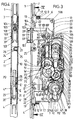
- the espagnolette lock has a lock housing 2 connected to a cuff 1.
- the cuff 1 fastened to one narrow side of the lock housing 2 has a greater length than the lock housing 2 and extends over an upper and a lower drive rod 3 or, respectively, emerging from the lock housing 2. 4.
- the latter are provided with locking members 5 which cooperate with counter-closing parts, not shown, on the frame.
- bearing blocks 8 extend from the rear surface of the cuff 1 and continue to form a step in rearward-facing fastening projections 9.
- the fastening projections 9 projecting over the narrow side walls 6, 7 have a trapezoidal shape such that the base of the trapezium faces the interior of the lock housing.
- both the lock base 10 and the lock cover 11 running parallel thereto form insertion pockets 12 and 13 on the narrow side walls.
- the pocket 12 formed by the lock base 10 is obtuse-angled.
- An angular section 12 'lies on the facing side wall of the fastening projection 9, while the adjoining angular section 12' is supported flat on the trapezoidal surface opposite the base.
- the angle section 12 ' is equipped with a passage opening 14 which is aligned with a threaded bore 15 of the fastening projection 9. Otherwise, this threaded hole runs parallel to the cuff 1.
- the other insertion pocket 13 in turn also has an angular shape.
- the directly from the castle ceiling 11 angle leg 13 ' is supported on the facing oblique flank of the trapezoidal fastening projection 9.
- the adjoining angle leg 13 ⁇ extends over the angle leg 12 ⁇ and lies flat on this.
- There the angle leg 13 ⁇ is equipped with a hole 16.
- the outer surface 18 of the bearing blocks 8 is convexly curved.
- the outer surface of the fastening projections 9 and the insertion pockets 12, 13 formed by angled portions also extend within this convex curvature, cf. 5 and 6. This makes it possible to produce pockets on the doors that are adapted to the shape of the lock housing at the height of the bearing blocks 8.
- Each bearing block 8 has a projection 19 with an oval cross section for fixing it on the cuff 1, which is inserted into a shape-adapted recess 20 of the cuff and riveted there, cf. 5 and 7 in particular.
- the bearing blocks 8 form centering brackets 22, which are immersed in shape-matched edge recesses in the lock base 10 and lock cover 11.
- the aforementioned centering tabs 22 are flush with the outer surfaces of the lock base 10 and lock cover 11.
- the lower drive rod 4 is forked in the region of the section crossing the bearing block 8.
- a longitudinal slot 29 is formed by the two fork tines 4 ', 4 ⁇ .
- Each fork 4 '. 4 ⁇ is provided with an angled end portion E, E ', which rest on the lock base 10 and immerse in shape-matched coupling recesses 31, 32 of a drive rod connecting slide 28 lying flat on the lock base 10.
- the aforementioned longitudinal slot 29 extends at the level of a through hole 30 of the cuff 1 for a lock cylinder fastening screw 30 '.
Abstract
Description
Die Erfindung betrifft ein Schloß, insbesondere Treibstangenschloß, gemäß Gattungsbegriff des Patentansprüche 1 und 2.The invention relates to a lock, in particular espagnolette lock, according to the preamble of
Es ist bei Schlössern, insbesondere Treibstangenschlössern, bekannt, von der der Stulpe zugekehrten Kante des Schloßbodens freigeschnittene Laschen abzuwinkeln und diese mit der Stulpe entweder durch Punktschweißen oder mittels Vernietung zu verbinden. Schloßboden und Stulpe stellen dadurch eine fest zusammenhängende Baueinheit dar, welcher bei der späteren Montage das Schloßeingerichte zugeordnet wird. Unterschiedlich gestaltete Schloßtypen verlangen von vornherein entsprechend gestaltete, aus Stulpe, Schloßboden und Schloßeingerichte bestehende Baueinheiten. Die Möglichkeit, einen Schloßtyp mit unterschiedlich gestalteten Stulpen zu kombinieren, ist nicht gegeben. Unterschiedliche Schloßtypen können z.B. dadurch gebildet sein, daß verschieden große Abstandsmaße zwischen Drückerdorn und Drehachse des Schlüssels vorliegen. Ferner können sie unterschiedliche Dornmaße aufweisen.With locks, in particular espagnolette locks, it is known to bend tabs cut free from the edge of the lock base facing the cuff and to connect these to the cuff either by spot welding or by riveting. The lock base and cuff thus form a firmly connected unit, which will be assigned to the lock set-up during subsequent assembly. Different types of locks require correspondingly designed units consisting of a cuff, lock base and lock fittings. There is no possibility to combine a lock type with differently designed gauntlets. Different types of locks can e.g. be formed by the fact that there are different sizes of distance between the arbor and the axis of rotation of the key. Furthermore, they can have different backsets.
Dem Gegenstand der Erfindung liegt die Aufgabe zugrunde, die Herstellung entsprechender Schlösser unter Erhöhung der Variationsmöglichkeit zu vereinfachen. Gelöst wird diese Aufgabe durch die im Patentanspruch 1 bzw. 2 angegebene Lösung.The object of the invention is based on the task of simplifying the manufacture of corresponding locks while increasing the possibility of variation. This object is achieved by the solution specified in
Die Unteransprüche betreffen vorteilhafte Weiterbildungen der erfinderischen Lösung.The subclaims relate to advantageous developments of the inventive solution.
Zufolge derartiger Ausgestaltung ist ein Schloß, insbesondere Treibstangenschloß, geschaffen, was der Fertigung unterschiedlich gestalteter Schlösser nach dem Baukastensystem entgegenkommt. Die Schloßgehäuse können unter Verwirklichung unterschiedlicher Schloßtypen vorgefertigt und montiert sein. Gleiches gilt für die Stulpen. Je nach Einsatzzweck kann dann die entsprechende Stulpe dem Schloßgehäuse bei leichter Montage zugeordnet werden. Das heißt, daß die Stulpe z. B. vor Auslieferung an dem das Schloßeingerichte aufnehmenden Schloßgehäuse festgelegt wird. Die Verbindung von Stulpe und Schloßgehäuse geschieht über die an der Rückfläche der Stulpe vorgesehenen, über die Schmalseitenwände des Schloßgehäuses kragenden Befestigungsvorsprünge. Daher ist eine gute Zugänglichkeit gegeben, die kurzfristig das Verbinden der Stulpe mit dem Schloßgehäuse zuläßt. Als Verbundmittel eignen sich insbesondere parallel zur Stulpe gerichtete Bolzen. Sind diese als Schrauben gestaltet, so brauchen zur Festlegung der Stulpe an dem Schloßgehäuse nur die entsprechenden Schrauben in Verbundeingriff gebracht zu werden. Durch an den Schmalseitenwänden vorgesehene Einstecktaschen für die Befestigungsvorsprünge ist das Montieren der Stulpe mit den daran befindlichen Befestigungsvorsprüngen im Wege der Steckmontage möglich. Danach sind anschließend die Bolzen unter Durchsetzen der Einstecktaschen in die Gewindebohrung der Befestigungsvorsprünge einzuschrauben. In einfacher Weise sind die Einstecktaschen von Abwinkelungen vom Schloßboden und Schloßdecke gebildet. Die Endabschnitte der Abwinkelungen der in einer Schmalseite vorgesehenen Einstecktasche überlappen sich. Der entsprechende Überlappungsbereich wird von dem Bolzen durchsetzt, welcher in die Gewindebohrung des Befestigungsvorsprunges eingeschraubt ist. Eine Mehrfachfunktion wird durch die Tatsache erreicht, die Befestigungsvorsprünge an Lagerböckchen für diese durchsetzende Treibstangen vorzusehen. Gesonderte Schlitzführungen im Bereich des Schloßgehäuses können dann für die Treibstangen entfallen. Auch bilden die Stulpe mit den Treibstangen vor der Montage eine fest zusammenhängende Baueinheit, was das Ansetzen derselben an das Schloßgehäuse erleichtert. In günstiger Weise sind die Außenfläche der Befestigungsvorsprünge, Taschen, Lagerböckchen konvex gekrümmt gestaltet bzw. besitzen einen entsprechenden Verlauf. Die in die Tür einzuarbeitende Tasche wird demgemäß voll von dem Schloßgehäuse mit Lagerböckchen und Befestigungsvorsprüngen sowie Einstecktaschen vollständig ausgefüllt. Im übrigen entsteht dadurch ein Zentriereffekt, so daß nach Einsetzen des Schloßgehäuses in die Tasche der Tür die Queröffnungen für den Drückerdorn und Schließzylinder vorschriftsmäßig mit der Nußachse bzw. der Schlüsseldrehachse fluchten. Das Ansetzen der Stulpe mit Treibstangen wird durch letztere nicht erschwert. Diese sind in Formschlußeingriff mit den entsprechenden Treibstangen-Anschlußschiebern zu bringen. Mindestens die eine Treibstange ist im Bereich ihres das Lagerböckchen kreuzenden Abschnittes gegabelt. Beide Gabelzinken treten je für sich in gesonderten Formschlußeingriff mit dem ihnen zugeordneten Treibstangen-Anschlußschieber unter Verwirklichung einer stabilen Mitnahmeverbindung. Die Fesselung des Schloßgehäuses an der Stulpe ist noch durch mindestens eine Zusatz-Befestigungsstelle zwischen Stulpe und Schloßboden verstärkt. Hierzu dient ein den Schloßboden durchsetzender Bolzen, der in einen weiteren an der Rückseite der Stulpe vorstehenden Vorsprung eingreift. Dieser Bolzen kann ebenfalls als Schraubbolzen gestaltet werden. Dessen Ausrichtung liegt jedoch quer zu den anderen beiden Schraubbolzen, so daß sich durch diesen Verlauf der drei Bolzen eine besonders hohe Befestigungsstabilität der Stulpe am Schloßgehäuse ergibt.As a result of such a design, a lock, in particular an espagnolette lock, is created, which is of manufacture differently designed locks according to the modular system. The lock housing can be prefabricated and assembled using different lock types. The same applies to the gauntlets. Depending on the application, the corresponding cuff can then be assigned to the lock housing with easy assembly. That means that the cuff z. B. is fixed before delivery to the lock housing receiving the lock mechanism. The cuff and lock housing are connected via the fastening projections provided on the rear surface of the cuff and projecting over the narrow side walls of the lock housing. Therefore, there is good accessibility, which allows the cuff to be connected to the lock housing in the short term. Bolts which are oriented parallel to the cuff are particularly suitable as a compound. If these are designed as screws, only the corresponding screws need to be brought into composite engagement to fix the cuff to the lock housing. By inserting pockets on the narrow side walls for the fastening projections, it is possible to mount the cuff with the fastening projections thereon by means of plug-in assembly. Then the bolts are then screwed into the threaded hole of the fastening projections while pushing through the pockets. In a simple manner, the pockets are formed by bends from the castle floor and castle ceiling. The end sections of the bends of the insertion pocket provided in a narrow side overlap. The corresponding overlap area is penetrated by the bolt which is screwed into the threaded bore of the fastening projection. A multiple function is achieved by the fact that the fastening projections on the bearing blocks are provided for the drive rods penetrating them. Separate slot guides in the area of the lock housing can then be omitted for the drive rods. The cuff with the drive rods form a firmly connected structural unit before assembly, which makes it easier to attach them to the lock housing. The outer surface of the fastening projections, pockets, bearing blocks are advantageously designed to be convexly curved or have a corresponding course. The pocket to be incorporated into the door is therefore completely filled by the lock housing with bearing blocks and fastening projections as well as insertion pockets. In addition, this creates a centering effect, so that after inserting the lock housing into the pocket of the door, the transverse openings for the handle pin and lock cylinder are correctly aligned with the nut axis or the key axis of rotation. The latter does not make it difficult to attach the cuff with connecting rods. These are to be brought into positive engagement with the corresponding connecting rod connecting slides. At least one drive rod is forked in the area of its section crossing the bearing block. Both fork tines each engage in a separate positive engagement with the associated connecting rod connecting slide, with the realization of a stable entrainment connection. The lock of the lock housing on the cuff is reinforced by at least one additional attachment point between the cuff and the lock base. For this purpose, a bolt penetrating the lock base is used, which engages in a further projection protruding on the rear of the cuff. This bolt can also be designed as a bolt. However, its alignment is transverse to the other two bolts, so that this course of the three bolts results in a particularly high fastening stability of the cuff on the lock housing.
Nachstehend wird ein Ausführungsbeispiel der Erfindung anhand der Zeichnungen erläutert. Es zeigt
- Fig. 1
- eine Ansicht des Treibstangenschlosses bei zurückgeschlossenem Riegel,
- Fig. 2
- eine klappfigürliche Darstellung der Fig. 1,
- Fig. 3
- eine Ansicht des Schloßgehäuses bei fortgelassener Schloßdecke, wobei sich der Zahnkranz in der Grundstellung befindet, die das Einsetzen eines Schließzylinders erlaubt,
- Fig. 4
- den Schnitt nach der Linie IV-IV in Fig. 4,
- Fig. 5
- in vergrößerter Darstellung den oberen Bereich des Treibstangenschlosses gemäß der Stellung, die sich bei zurückgeschlossenem Riegel und abgezogenem Schlüssel ergibt, teils in Ansicht, teils im Längsschnitt,
- Fig. 6
- den Schnitt nach der Linie VI-VI in Fig. 5,
- Fig. 7
- teils in Ansicht, teils im Schnitt die Stulpe mit Lagerböckchen und Befestigungsvorsprüngen vor dem Verbinden mit dem Schloßboden und der Schloßdecke, und
- Fig. 8
- die klappfigürliche Darstellung der Fig. 7.
- Fig. 1
- a view of the espagnolette lock with the bolt closed,
- Fig. 2
- 2 shows a foldable illustration of FIG. 1,
- Fig. 3
- 2 shows a view of the lock housing with the lock cover removed, the toothed ring being in the basic position, which allows the insertion of a lock cylinder,
- Fig. 4
- the section along the line IV-IV in Fig. 4,
- Fig. 5
- in an enlarged view the upper area of the espagnolette lock according to the position that results when the bolt is closed and the key is removed, partly in view, partly in longitudinal section,
- Fig. 6
- the section along the line VI-VI in Fig. 5,
- Fig. 7
- partly in view, partly in section, the cuff with bearing blocks and fastening projections before connecting to the lock base and cover, and
- Fig. 8
- the folding figure of Fig. 7th
Das Treibstangenschloß besitzt ein mit einer Stulpe 1 verbundenes Schloßgehäuse 2. Die an der einen Schmalseite des Schloßgehäuses 2 befestigte Stulpe 1 weist dabei eine größere Länge als das Schloßgehäuse 2 auf und überfängt eine obere und eine untere, aus dem Schloßgehäuse 2 austretende Treibstange 3 bzw. 4. Letztere sind mit Riegelgliedern 5 versehen, die mit rahmenseitigen, nicht dargestellten Gegenschließteilen zusammenwirken.The espagnolette lock has a
Auf Höhe der Schmalseitenwände 6, 7 gehen von der Rückfläche der Stulpe 1 Lagerböckchen 8 aus, die sich unter Ausbildung einer Stufe in nach rückwärts gerichtete Befestigungsvorsprünge 9 fortsetzen. Im Querschnitt gesehen, besitzen die über die Schmalseitenwände 6, 7 kragenden Befestigungsvorsprünge 9 eine Trapezform derart, daß die Basis des Trapezes dem Schloßgehäuseinneren zugekehrt ist. Für die Befestigungsvorsprünge 9 bilden sowohl der Schloßboden 10 als auch die parallel dazu verlaufende Schloßdecke 11 an den Schmalseitenwänden Einstecktaschen 12 bzw. 13 aus. Die von dem Schloßboden 10 gebildete Einstecktasche 12 ist stumpfwinklig gestaltet. Der eine Winkelabschnitt 12′ liegt an der zugekehrten Seitenwand des Befestigungsvorsprunges 9 an, während der sich anschließende Winkelabschnitt 12˝ sich flächig an der der Basis gegenüberliegenden Trapezfläche abstützt. Der Winkelabschnitt 12˝ ist mit einer Durchtrittsöffnung 14 ausgestattet, die mit einer Gewindebohrung 15 des Befestigungsvorsprunges 9 fluchtet. Im übrigen verläuft siese Gewindebohrung parallel zur Stulpe 1.At the level of the
Die andere Einstecktasche 13 ihrerseits besitzt ebenfalls Winkelform. Der unmittelbar von der Schloßdecke 11 ausgehende Winkelschenkel 13′ findet Abstützung an der zugekehrten Schrägflanke des trapezförmigen Befestigungsvorsprunges 9. Der sich daran anschließende Winkelschenkel 13˝ überfängt den Winkelschenkel 12˝ und liegt flächig auf diesem auf. Dort ist der Winkelschenkel 13˝ mit einem Loch 16 ausgestattet. Mittels eines die Einstecktaschen 12, 13 durchgreifenden und in die Gewindebohrung 15 des Befestigungsvorsprungs 9 eintretenden, als Schraube gestalteten Bolzens 17 können Stulpe 1, Schloßboden 10 und Schloßdecke 11 zu einer Baueinheit verbunden werden.The
Die Außenfläche 18 der Lagerböckchen 8 verläuft konvex gekrümmt. Innerhalb dieser konvexen Krümmung erstrecken sich ebenfalls die Außenfläche der Befestigungsvorsprünge 9 sowie der von Abwinklungen gebildeten Einstecktaschen 12, 13, vgl. insbesondere Fig. 5 und 6. Hierdurch ist es möglich, an den Türen Taschen zu erzeugen, die der Umrißform des Schloßgehäuses auf Höhe der Lagerböckchen 8 angepaßt sind.The
Jedes Lagerböckchen 8 besitzt zu seiner Festlegung an der Stulpe 1 einen im Querschnitt ovalen Vorsprung 19, der in eine formangepaßte Ausnehmung 20 der Stulpe eingesetzt und dort vernietet ist, vgl. insbesondere Fig. 5 und 7.Each
Seitlich der Durchtrittskanäle 21 für die Treibstangen 3, 4 bilden die Lagerböckchen 8 Zentrierlaschen 22 aus, welche in formangepaßte Randaussparungen von Schloßboden 10 und Schloßdecke 11 eintauchen. Die vorgenannten Zentrierlaschen 22 schließen dabei bündig mit den Außenflächen von Schloßboden 10 und Schloßdecke 11 ab.At the side of the
Es ist sodann noch eine Zusatz-Befestigungsstelle zwischen Stulpe 1 und Schloßboden 10 vorgesehen. Bestandteil derselben ist ein an der Rückfläche der Stulpe 1 befestigter Vorsprung 24, welcher sich im Bereich zwischen beiden Lagerböckchen 8 erstreckt. In dem Vorsprung 24 ist eine Gewindebohrung 25 zur Aufnahme eines ebenfalls als Schraube gestalteten Bolzens 26 vorgesehen. Letzterer verläuft parallel zur Stulpe 1, ist jedoch rechtwinklig zu den anderen Bolzen 17 ausgerichtet, da er durch ein Loch 27 des Schloßbodens 10 her eingeschraubt ist. Auf diese Weise können unterschiedlich gestaltete Stulpen 1 mit Treibstangen 3, 4 bei leichter Montage mit eventuell auch unterschiedlich gestalteten Schloßgehäusen 2 verbunden werden.An additional fastening point between
Beim Ausführungsbeispiel ist die untere Treibstange 4 im Bereich des das Lagerböckchen 8 kreuzenden Abschnittes gegabelt. Durch die beiden Gabelzinken 4′, 4˝ wird ein Längsschlitz 29 geformt. Jeder Gabelzinken 4′. 4˝ ist mit einem abgewinkelten Endabschnitt E, E′ versehen, welche auf dem Schloßboden 10 aufliegen und in formangepaßte Kupplungsaussparungen 31, 32 eines flächig auf dem Schloßboden 10 aufliegenden Treibstangen-Anschlußschiebers 28 eintauchen. Der vorgenannte Längsschlitz 29 erstreckt sich im übrigen auf Höhe eines Durchtrittsloches 30 der Stulpe 1 für eine Schließzylinder-Befestigungsschraube 30′.In the exemplary embodiment, the
Claims (8)
- Lock, in particular driving rod lock, with a cuff plate (1) fixed to one first narrow side of the lock housing (2), characterised in that the cuff plate (1) is provided on its rear flank with fixing projections (9) protruding beyond the second narrow sides (6, 7) of the lock housing (2) which extend perpendicularly to the first narrow sides.
- Lock, in particular driving rod lock, with a cuff plate (1) fixed to one first narrow side of the lock housing (2), characterised in that the walls of the narrow sides (6, 7) extending perpendicularly to the first narrow sides are provided with insertion recesses (12, 13) for fixing projections (9) provided on the cuff plate.
- Lock according to claim 1 or 2, characterised in that the fixing projections (9) are held on the narrow side walls (6, 7) by bolts (17) oriented parallel to the cuff plate (1).
- Lock according to any of the preceding claims, characterised in that the insertion recesses (12, 13) are formed by bent portions of lock bottom (10) and lock top (11).
- Lock, in particular driving rod lock, according to any of the preceding claims, characterised in that the fixing projections (9) extend from bearing blocks (8) for driving rods (3, 4) which pass through the latter.
- Lock, in particular driving rod lock, according to any of the preceding claims, characterised in that the outer surface (18) of the fixing projections/recess/bearing blocks is convexly curved.
- Lock, in particular driving rod lock, according to any of the preceding claims, characterised in that one driving rod (4) is forked in the region of its section crossing the bearing block, and both fork prongs (4′, 4˝) are each independently in separate form-locking engagement with a driving rod connecting slide (28).
- Lock according to any of the preceding claims, characterised by at least one additional fixing point between cuff plate (1) and lock bottom (10) via a bolt (26) which passes through the lock bottom (10) and which engages in a projection (24) protruding on the rear side of the cuff plate (1).
Priority Applications (1)
| Application Number | Priority Date | Filing Date | Title |
|---|---|---|---|
| EP93114824A EP0581326B1 (en) | 1990-05-02 | 1991-02-25 | Cremone lock |
Applications Claiming Priority (2)
| Application Number | Priority Date | Filing Date | Title |
|---|---|---|---|
| DE4014040A DE4014040A1 (en) | 1990-05-02 | 1990-05-02 | LOCK, PARTICULAR DRIVE ROD LOCK |
| DE4014040 | 1990-05-02 |
Related Child Applications (2)
| Application Number | Title | Priority Date | Filing Date |
|---|---|---|---|
| EP93114824A Division EP0581326B1 (en) | 1990-05-02 | 1991-02-25 | Cremone lock |
| EP93114824.1 Division-Into | 1993-09-15 |
Publications (2)
| Publication Number | Publication Date |
|---|---|
| EP0454958A1 EP0454958A1 (en) | 1991-11-06 |
| EP0454958B1 true EP0454958B1 (en) | 1994-06-22 |
Family
ID=6405552
Family Applications (2)
| Application Number | Title | Priority Date | Filing Date |
|---|---|---|---|
| EP93114824A Expired - Lifetime EP0581326B1 (en) | 1990-05-02 | 1991-02-25 | Cremone lock |
| EP91102726A Expired - Lifetime EP0454958B1 (en) | 1990-05-02 | 1991-02-25 | Lock, in particular lock with driving rod |
Family Applications Before (1)
| Application Number | Title | Priority Date | Filing Date |
|---|---|---|---|
| EP93114824A Expired - Lifetime EP0581326B1 (en) | 1990-05-02 | 1991-02-25 | Cremone lock |
Country Status (3)
| Country | Link |
|---|---|
| EP (2) | EP0581326B1 (en) |
| AT (2) | ATE107732T1 (en) |
| DE (3) | DE4014040A1 (en) |
Families Citing this family (6)
| Publication number | Priority date | Publication date | Assignee | Title |
|---|---|---|---|---|
| DE9208526U1 (en) * | 1992-06-25 | 1992-09-10 | Gretsch-Unitas Gmbh Baubeschlaege, 7257 Ditzingen, De | |
| HU214809B (en) * | 1993-11-22 | 1998-05-28 | János Fehérdi | Lock |
| KR100948720B1 (en) | 2005-05-12 | 2010-03-22 | 미쓰이 가가쿠 가부시키가이샤 | Lactic acid polymer composition, molded article made of same, and method for producing such molded article |
| AT513464B1 (en) * | 2012-09-06 | 2015-01-15 | Roto Frank Ag | Lock with multiple bolts |
| AT14921U1 (en) * | 2015-02-19 | 2016-08-15 | Roto Frank Ag | lock |
| US11572706B2 (en) | 2020-07-01 | 2023-02-07 | Cmech (Guangzhou) Ltd. | Handle-locking mechanism and door lock using such mechanism |
Family Cites Families (8)
| Publication number | Priority date | Publication date | Assignee | Title |
|---|---|---|---|---|
| US4237711A (en) * | 1978-02-10 | 1980-12-09 | Brink's Locking Systems, Inc. | Lock mechanism |
| JPS5833348B2 (en) * | 1979-08-23 | 1983-07-19 | 基博 五反田 | locking device |
| FR2488318B1 (en) * | 1980-08-08 | 1985-07-26 | Chauvat Sofranq | THREE POINT TYPE LATCHING LOCK |
| AT366750B (en) * | 1980-11-13 | 1982-05-10 | Grundmann Rohrbacher Schlosser | DOOR LOCK |
| DE3142959C2 (en) * | 1981-08-04 | 1985-06-05 | BKS Sicherheitstechnik GmbH, 5040 Brühl | Espagnolette lock for doors |
| AU557075B2 (en) * | 1981-11-19 | 1986-12-04 | Lockwood Security Products Pty Limited | Screen door lock |
| GB8517168D0 (en) * | 1985-07-05 | 1985-08-14 | Gkn Crompton | Latch mechanism |
| GB8811734D0 (en) * | 1988-05-18 | 1988-06-22 | Goodwin W J & Son Ltd | Improvements in/relating to locking mechanisms |
-
1990
- 1990-05-02 DE DE4014040A patent/DE4014040A1/en not_active Withdrawn
-
1991
- 1991-02-25 DE DE59101979T patent/DE59101979D1/en not_active Expired - Fee Related
- 1991-02-25 EP EP93114824A patent/EP0581326B1/en not_active Expired - Lifetime
- 1991-02-25 AT AT91102726T patent/ATE107732T1/en not_active IP Right Cessation
- 1991-02-25 EP EP91102726A patent/EP0454958B1/en not_active Expired - Lifetime
- 1991-02-25 DE DE59109131T patent/DE59109131D1/en not_active Expired - Fee Related
- 1991-02-25 AT AT93114824T patent/ATE180539T1/en not_active IP Right Cessation
Also Published As
| Publication number | Publication date |
|---|---|
| ATE180539T1 (en) | 1999-06-15 |
| EP0454958A1 (en) | 1991-11-06 |
| ATE107732T1 (en) | 1994-07-15 |
| DE59101979D1 (en) | 1994-07-28 |
| DE4014040A1 (en) | 1991-11-07 |
| EP0581326A1 (en) | 1994-02-02 |
| EP0581326B1 (en) | 1999-05-26 |
| DE59109131D1 (en) | 1999-07-01 |
Similar Documents
| Publication | Publication Date | Title |
|---|---|---|
| EP0513031A1 (en) | Lock with locking function released by inserting a key card with a magnetized region. | |
| EP0454958B1 (en) | Lock, in particular lock with driving rod | |
| DE3645256C2 (en) | Lock for door or window | |
| EP1209305A1 (en) | Construction element system for the assembly of cylinder locks | |
| DE4014041A1 (en) | LOCKING CYLINDER ACTUATED ROD LOCK | |
| DE2239390A1 (en) | MOCKET LOCK FOR DOORS | |
| DE3111247A1 (en) | Mortise lock | |
| EP0454966A1 (en) | Lock with driving rod operated by locking cylinder | |
| EP0454959B1 (en) | Plug actuated sliding bar lock | |
| EP0454960B1 (en) | Espagnolette | |
| DE3600435C2 (en) | ||
| DE10100763B4 (en) | Mortise lock with plastic latch | |
| EP0454965B1 (en) | Mortise lock, in particular lock with driving rod | |
| EP2735675B1 (en) | Closure device for doors with an asymmetric escutcheon | |
| AT402651B (en) | TRANSMISSION FOR A LOCKING BAR FITTING OF A TRANSMISSION FOR A LOCKING BAR FITTING OF A DOOR OR WINDOW DOOR OR WINDOW | |
| EP1103676B1 (en) | Espagnolette lock | |
| DE2327086A1 (en) | CUP RAIL CORNER CONNECTION, ESPECIALLY ON DRIVE ROD FITTINGS | |
| EP0163816B1 (en) | Connection device for actuating bars, espcially for fittings of tilting and pivoting wings such as windows, doors or the like | |
| DE2804603C2 (en) | Bolt blocking device in a lock with key operated tumbler | |
| DE2435847B1 (en) | Coupling mechanism for asymmetrical cylinder lock - has coupling component between two halves for opposing keys | |
| DE4302920C2 (en) | Lock, especially mortise lock | |
| DE10147373A1 (en) | door frame | |
| DE8426131U1 (en) | PROFILE FRAME FOR A WINDOW, A DOOR OR. DGL. WITH A GEARBOX HANDLE OD. DGL. | |
| DE3346711A1 (en) | Furniture hinge for doors, flaps or the like | |
| EP1195485A2 (en) | Lock actuated by a lever handle |
Legal Events
| Date | Code | Title | Description |
|---|---|---|---|
| PUAI | Public reference made under article 153(3) epc to a published international application that has entered the european phase |
Free format text: ORIGINAL CODE: 0009012 |
|
| AK | Designated contracting states |
Kind code of ref document: A1 Designated state(s): AT DE FR GB IT |
|
| 17P | Request for examination filed |
Effective date: 19910919 |
|
| 17Q | First examination report despatched |
Effective date: 19930824 |
|
| GRAA | (expected) grant |
Free format text: ORIGINAL CODE: 0009210 |
|
| AK | Designated contracting states |
Kind code of ref document: B1 Designated state(s): AT DE FR GB IT |
|
| REF | Corresponds to: |
Ref document number: 107732 Country of ref document: AT Date of ref document: 19940715 Kind code of ref document: T |
|
| GBT | Gb: translation of ep patent filed (gb section 77(6)(a)/1977) |
Effective date: 19940622 |
|
| REF | Corresponds to: |
Ref document number: 59101979 Country of ref document: DE Date of ref document: 19940728 |
|
| ET | Fr: translation filed | ||
| ITF | It: translation for a ep patent filed |
Owner name: STUDIO JAUMANN |
|
| PLBE | No opposition filed within time limit |
Free format text: ORIGINAL CODE: 0009261 |
|
| STAA | Information on the status of an ep patent application or granted ep patent |
Free format text: STATUS: NO OPPOSITION FILED WITHIN TIME LIMIT |
|
| 26N | No opposition filed | ||
| REG | Reference to a national code |
Ref country code: GB Ref legal event code: IF02 |
|
| PGFP | Annual fee paid to national office [announced via postgrant information from national office to epo] |
Ref country code: AT Payment date: 20061222 Year of fee payment: 17 Ref country code: DE Payment date: 20061222 Year of fee payment: 17 |
|
| PGFP | Annual fee paid to national office [announced via postgrant information from national office to epo] |
Ref country code: GB Payment date: 20061228 Year of fee payment: 17 |
|
| PGFP | Annual fee paid to national office [announced via postgrant information from national office to epo] |
Ref country code: IT Payment date: 20070612 Year of fee payment: 17 |
|
| PGFP | Annual fee paid to national office [announced via postgrant information from national office to epo] |
Ref country code: FR Payment date: 20061220 Year of fee payment: 17 |
|
| GBPC | Gb: european patent ceased through non-payment of renewal fee |
Effective date: 20080225 |
|
| PG25 | Lapsed in a contracting state [announced via postgrant information from national office to epo] |
Ref country code: AT Free format text: LAPSE BECAUSE OF NON-PAYMENT OF DUE FEES Effective date: 20080225 |
|
| REG | Reference to a national code |
Ref country code: FR Ref legal event code: ST Effective date: 20081031 |
|
| PG25 | Lapsed in a contracting state [announced via postgrant information from national office to epo] |
Ref country code: DE Free format text: LAPSE BECAUSE OF NON-PAYMENT OF DUE FEES Effective date: 20080902 |
|
| PG25 | Lapsed in a contracting state [announced via postgrant information from national office to epo] |
Ref country code: FR Free format text: LAPSE BECAUSE OF NON-PAYMENT OF DUE FEES Effective date: 20080229 |
|
| PG25 | Lapsed in a contracting state [announced via postgrant information from national office to epo] |
Ref country code: GB Free format text: LAPSE BECAUSE OF NON-PAYMENT OF DUE FEES Effective date: 20080225 |
|
| PG25 | Lapsed in a contracting state [announced via postgrant information from national office to epo] |
Ref country code: IT Free format text: LAPSE BECAUSE OF NON-PAYMENT OF DUE FEES Effective date: 20080225 |