EP0454922B1 - Macerating machine - Google Patents
Macerating machine Download PDFInfo
- Publication number
- EP0454922B1 EP0454922B1 EP90310148A EP90310148A EP0454922B1 EP 0454922 B1 EP0454922 B1 EP 0454922B1 EP 90310148 A EP90310148 A EP 90310148A EP 90310148 A EP90310148 A EP 90310148A EP 0454922 B1 EP0454922 B1 EP 0454922B1
- Authority
- EP
- European Patent Office
- Prior art keywords
- cutter
- axis
- teeth
- tooth
- cutters
- Prior art date
- Legal status (The legal status is an assumption and is not a legal conclusion. Google has not performed a legal analysis and makes no representation as to the accuracy of the status listed.)
- Expired - Lifetime
Links
- 230000002879 macerating effect Effects 0.000 title description 3
- 125000006850 spacer group Chemical group 0.000 claims abstract description 8
- 239000007787 solid Substances 0.000 description 4
- 238000002803 maceration Methods 0.000 description 2
- 238000010276 construction Methods 0.000 description 1
- 230000003292 diminished effect Effects 0.000 description 1
- 239000000463 material Substances 0.000 description 1
- 239000010865 sewage Substances 0.000 description 1
- 230000036346 tooth eruption Effects 0.000 description 1
Images
Classifications
-
- B—PERFORMING OPERATIONS; TRANSPORTING
- B02—CRUSHING, PULVERISING, OR DISINTEGRATING; PREPARATORY TREATMENT OF GRAIN FOR MILLING
- B02C—CRUSHING, PULVERISING, OR DISINTEGRATING IN GENERAL; MILLING GRAIN
- B02C18/00—Disintegrating by knives or other cutting or tearing members which chop material into fragments
- B02C18/06—Disintegrating by knives or other cutting or tearing members which chop material into fragments with rotating knives
- B02C18/16—Details
- B02C18/18—Knives; Mountings thereof
- B02C18/182—Disc-shaped knives
Definitions
- the present invention relates to macerators and to a rotatable cutter for use in such a macerator.
- One form of macerator includes first and second parallel contra-rotating shafts, each having a plurality of alternate cutters and spacers of the same axial thickness, the cutters of the first shaft being interleaved with those of the second shaft.
- Each cutter has a plurality of teeth arranged around its periphery at circumferentially spaced locations. According to GB-A-1569672 the teeth are each symmetrical with respect to a radial plane through the circumferential centre thereof. This is supposed to provide the advantage that the macerator can be reversed to give some form of clearing action and more importantly, when the leading edges of the teeth become worn, the cutters can be reversed so that the rear edges then become the leading edges.
- the front faces of the cutters are inclined to the axis of the cutters, thus of the shaft associated therewith, and there can be a considerable tendency for the product being macerated to become jammed thereby seizing up the whole macerator.
- a rotatable cutter for a macerator of the type having first and second parallel contra-rotating shafts, each having a plurality of alternate cutters and spacers of the same axial thickness, the cutters of the first shaft being interleaved with those of the second shaft, each said cutter having several circumferentially spaced teeth, each tooth having a front cutting face, and a generally ramp shaped, inclined, circumferential rear face.
- Such cutters are e.g. known from US-A-3880361.
- the invention is further characterised in that the front face of at least one tooth extends substantially parallel to the axis of the cutter and the front faces of a plurality of the other teeth are inclined to the axis of the cutter and thus inclined to the front face of said at least one tooth.
- the macerator By having the back of the teeth inclined, if a jam begins to occur, or occurs, the macerator can be reversed and the ramp shaped rear faces urge the material being macerated radially outwardly toward the inlet, thereby relieving the jam.
- At least one tooth has a "square" cutting face, it has been found that this improves catchment of the solids, and the drag of the item into the bank of cutters of the macerator.
- the other teeth have alternately inclined faces to one side of the axis of the cutter and to the other side thereof, which gives an equalization of the side thrust on the cutters, this significantly reducing the possibility of breakage of the cutter teeth.
- front faces may be inclined at an angle of between 25°and 60° with respect to the axis of the cutter. It has been found advantageous, for example, with a five tooth cutter, to have an angle of about 30° and with a seven tooth cutter to have an angle of about 45°.
- the front face of the teeth may be arcuately concave. This tends to retain an item to be cut as the teeth rotate.
- the rear faces of the teeth may be serrated along at least part of their length and this assists in clearing solid matter during reversal of the cutters due to overload. It is has been found appropriate if the serrations define an angle 55°to 65° and preferably 60°.
- the rear of the teeth may be arcuately convex for a portion of their length between the serrations of the tooth tip and this again assists in the clearing action.
- the invention also provides a macerating machine having first and second parallel contra-rotating shafts, each having a plurality of alternate cutters and spacers of the same axial thickness, the cutters of the first shaft being interleaved with those of the second shaft, each cutter being a cutter of the invention.
- the cutter illustrated is to be mounted in a macerator of the type, for example, illustrated in GB-A-1569672.
- a macerator has two contra-rotating shafts upon which a plurality of cutters are mounted, there being inter-spaced between the cutters, spacers having substantially the same thickness as the cutters so that the cutters of one shaft interleave with those of the other to provide a good scissor action.
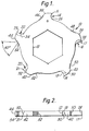
- the cutter 10 illustrated in Figure 1 is shown as having a central hexagonal opening 12 for engagement on the hexagonal shaft (not shown).
- the cutter is illustrated as having five circumferentially spaced teeth 14, 16, 18, 20, 22. It can be seen that each tooth has a tip 15, 17, 19, 21, 23 respectively and a generally arcuate concave front face 26, 28, 30, 32, 34.
- the front face 26 extends substantially parallel to the axis of the cutter, so that it is essentially "square".
- the front faces 28, 32 are angled to one side of the axis of the cutter and the alternate front faces 30, 34 are angled to the other side of the axis.
- the rear faces 36, 38, 40, 42, 44 are inclined to provide a ramp-like configuration and are each provided with serrations 46, 48, 50, 52, 54, the angle of the serrations being approximately 60°.
- the rear faces 36-44 are arcuately convex between the serrations 46-54 and the tips 15-23.
- the front faces 28, 30, 32, 34 are inclined at approximately 30° (see Figure 2) to the axis 11 in alternately opposite directions.
- the overall diameter of the cutters of the present invention can be increased so that there is less clearance between the cutter and the spacer on the other shaft and this reduces the clearance between the teeth and the machine body also, thereby giving finer maceration.
Landscapes
- Engineering & Computer Science (AREA)
- Food Science & Technology (AREA)
- Crushing And Pulverization Processes (AREA)
- Paper (AREA)
- Seal Device For Vehicle (AREA)
- Portable Nailing Machines And Staplers (AREA)
Abstract
Description
- The present invention relates to macerators and to a rotatable cutter for use in such a macerator.
- One form of macerator includes first and second parallel contra-rotating shafts, each having a plurality of alternate cutters and spacers of the same axial thickness, the cutters of the first shaft being interleaved with those of the second shaft. Each cutter has a plurality of teeth arranged around its periphery at circumferentially spaced locations. According to GB-A-1569672 the teeth are each symmetrical with respect to a radial plane through the circumferential centre thereof. This is supposed to provide the advantage that the macerator can be reversed to give some form of clearing action and more importantly, when the leading edges of the teeth become worn, the cutters can be reversed so that the rear edges then become the leading edges. While this is apparently an advantage in theory, in practice it does not work out because, when the macerator is used in an abrasive environment, for example in macerating raw sewage, the cutters become worn by progressively becoming thinner. As this happens, the scissor action produced by the teeth of the cutters associated with the two shafts is greatly diminished and proper maceration does not take place.
- The front faces of the cutters are inclined to the axis of the cutters, thus of the shaft associated therewith, and there can be a considerable tendency for the product being macerated to become jammed thereby seizing up the whole macerator.
- It is now proposed, according to the present invention, to provide a rotatable cutter for a macerator of the type having first and second parallel contra-rotating shafts, each having a plurality of alternate cutters and spacers of the same axial thickness, the cutters of the first shaft being interleaved with those of the second shaft, each said cutter having several circumferentially spaced teeth, each tooth having a front cutting face, and a generally ramp shaped, inclined, circumferential rear face. Such cutters are e.g. known from US-A-3880361. The invention is further characterised in that the front face of at least one tooth extends substantially parallel to the axis of the cutter and the front faces of a plurality of the other teeth are inclined to the axis of the cutter and thus inclined to the front face of said at least one tooth.
- By having the back of the teeth inclined, if a jam begins to occur, or occurs, the macerator can be reversed and the ramp shaped rear faces urge the material being macerated radially outwardly toward the inlet, thereby relieving the jam.
- Because at least one tooth has a "square" cutting face, it has been found that this improves catchment of the solids, and the drag of the item into the bank of cutters of the macerator. The other teeth have alternately inclined faces to one side of the axis of the cutter and to the other side thereof, which gives an equalization of the side thrust on the cutters, this significantly reducing the possibility of breakage of the cutter teeth.
- These front faces may be inclined at an angle of between 25°and 60° with respect to the axis of the cutter. It has been found advantageous, for example, with a five tooth cutter, to have an angle of about 30° and with a seven tooth cutter to have an angle of about 45°.
- In order to assist in the cutting action, the front face of the teeth may be arcuately concave. This tends to retain an item to be cut as the teeth rotate.
- The rear faces of the teeth may be serrated along at least part of their length and this assists in clearing solid matter during reversal of the cutters due to overload. It is has been found appropriate if the serrations define an angle 55°to 65° and preferably 60°.
- The rear of the teeth may be arcuately convex for a portion of their length between the serrations of the tooth tip and this again assists in the clearing action.
- To give a truly balanced cutting array, it is advantageous that only one tooth which has its front face extending substantially parallel to the axis of the cutter, the remaining teeth having their front faces inclined to the axis of the cutter.
- The invention also provides a macerating machine having first and second parallel contra-rotating shafts, each having a plurality of alternate cutters and spacers of the same axial thickness, the cutters of the first shaft being interleaved with those of the second shaft, each cutter being a cutter of the invention.
- In order that the present invention may more readily be understood, the following description is given, merely by way of example, reference being made to the accompanying drawings in which:-
- Figure 1 is a side elevation of one embodiment of cutter according to the invention;
- Figure 2 is a view of the cutter of Figure 1 from the edge; and
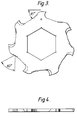
- Figures 3 and 4 are views similar to Figures 1 and 2, respectively, of a second embodiment.
- Referring first to Figure 1, the cutter illustrated is to be mounted in a macerator of the type, for example, illustrated in GB-A-1569672. Such a macerator has two contra-rotating shafts upon which a plurality of cutters are mounted, there being inter-spaced between the cutters, spacers having substantially the same thickness as the cutters so that the cutters of one shaft interleave with those of the other to provide a good scissor action.
- The
cutter 10 illustrated in Figure 1 is shown as having a centralhexagonal opening 12 for engagement on the hexagonal shaft (not shown). The cutter is illustrated as having five circumferentially spacedteeth tip front face front face 26 extends substantially parallel to the axis of the cutter, so that it is essentially "square". Thefront faces alternate front faces - The
rear faces serrations - It can be seen that the front faces 28, 30, 32, 34, are inclined at approximately 30° (see Figure 2) to the axis 11 in alternately opposite directions. When a plurality of these cutters are mounted as shown, there is provided a good scissor action and it will be observed that the cutting action takes place only in the one direction of rotation. This is bound to make the cutter stronger and less prone to damage. Because the backs of the cutting teeth are inclined and serrated, this assists in clearing the solid matter during reversal of the cutters due to overload. The one
tooth 14 has a "square" cutting face and this improves the catchment of the solids and the drag of the item being macerated into the bank of cutters. Because the other teeth have alternate angles this tends to equal out any side thrust and reduces the possibility of breakage. - It has been found that the overall diameter of the cutters of the present invention can be increased so that there is less clearance between the cutter and the spacer on the other shaft and this reduces the clearance between the teeth and the machine body also, thereby giving finer maceration.
- Detailed discussion of the construction of Figures 3 and 4 is not thought to be necessary because it is in many ways very similar to the cutter of Figures 1 and 2 except here seven teeth have been provided. Again one tooth is "square" and the other teeth are inclined in opposite angular directions. It has been found satisfactory here, because of the larger number of teeth, to have the angle of inclination of these cutters larger, for example approximately 45° to the axis of the cutter.
Claims (9)
- A rotatable flat disc shaped cutter for a macerator of the type having first and second parallel contra-rotating shafts, each having a plurality of alternate cutters (10) and spacers of the same axial thickness, the cutters of the first shaft being interleaved with those of the second shaft, said cutter (10) having several circumferentially spaced teeth (14-22), each tooth having a front cutting face (26-34), and a generally ramp shaped, inclined, circumferential rear face (36-44) characterised in that the front face (26) of at least one tooth extends parallel to the axis of rotation of the cutter, said axis being orthogonal to the flat faces of the cutter, and the front faces (28-34) of a plurality of the other teeth are inclined to said axis, and thus inclined to the front face (26) of said at least one tooth.
- A cutter according to claim 1, characterised in that the front faces (28-34) of said other teeth are inclined alternately to one side of the axis of the cutter and to the other side of the axis of the cutter.
- A cutter according to claim 1 or 2, characterised in that the front faces (28-34) of said other teeth are inclined at an angle of 25° to 50° with respect to the axis of the cutter.
- A cutter according to claim 1, 2 or 3, characterised in that the front faces (26-34) of the teeth are arcuately concave, as viewed along the axis of the cutter.
- A cutter according to any preceding claim, characterised in that the rear faces (36-44) of the teeth are serrated (46-54) along at least a part of their length.
- A cutter according to claim 5, characterised in that said serrations (46-54) define an angle of 55° to 65°.
- A cutter according to claim 5 or 6, characterised in that the rear face (36-44) of each tooth is arcuately convex for a portion of the length between the serrations (46-54) and the tip (5,17,19,21,23) of the tooth.
- A cutter according to any preceding claim, characterised in that there are an odd number of teeth, and in that there is only one tooth (14) which has its front face (26) extending substantially parallel to the axis of the cutter, the remaining teeth having their front faces inclined to the axis of the cutter.
- A macerator having first and second parallel contra-rotating shafts, each having a plurality of alternate cutters and spacers of the same axial thickness, the cutters of the first shaft being interleaved with those of the second shaft, each cutter being a cutter of any preceding claim.
Applications Claiming Priority (2)
| Application Number | Priority Date | Filing Date | Title |
|---|---|---|---|
| GB9009646A GB2243561B (en) | 1990-04-30 | 1990-04-30 | Macerating machine |
| GB9009646 | 1990-04-30 |
Publications (2)
| Publication Number | Publication Date |
|---|---|
| EP0454922A1 EP0454922A1 (en) | 1991-11-06 |
| EP0454922B1 true EP0454922B1 (en) | 1994-06-08 |
Family
ID=10675208
Family Applications (1)
| Application Number | Title | Priority Date | Filing Date |
|---|---|---|---|
| EP90310148A Expired - Lifetime EP0454922B1 (en) | 1990-04-30 | 1990-09-17 | Macerating machine |
Country Status (7)
| Country | Link |
|---|---|
| US (1) | US5141168A (en) |
| EP (1) | EP0454922B1 (en) |
| AT (1) | ATE106777T1 (en) |
| AU (1) | AU626022B2 (en) |
| DE (1) | DE69009740T2 (en) |
| ES (1) | ES2054261T3 (en) |
| GB (1) | GB2243561B (en) |
Families Citing this family (42)
| Publication number | Priority date | Publication date | Assignee | Title |
|---|---|---|---|---|
| JPH0753712Y2 (en) * | 1991-03-08 | 1995-12-13 | 株式会社キンキ | Cutting blade for shredder |
| GB2259260A (en) * | 1991-09-09 | 1993-03-10 | Mono Pumps Ltd | Macerator. |
| US5295633A (en) * | 1992-01-13 | 1994-03-22 | Fellowes Manufacturing Company | Document shredding machine with stripper and cutting mechanism therefore |
| US5375780A (en) * | 1993-05-24 | 1994-12-27 | Courtaulds Fibres (Holdings) Ltd. | Comminuting wood pulp sheeting |
| US5560552A (en) * | 1993-11-12 | 1996-10-01 | Environmental Products Corporation | Container cutting assembly |
| US5836527A (en) * | 1994-06-06 | 1998-11-17 | Irwin Research & Development | Apparatus for comminuting solid waste materials |
| WO1995033566A1 (en) * | 1994-06-06 | 1995-12-14 | Irwin Research & Development Inc. | An improved apparatus for comminuting solid waste materials |
| US5511729A (en) * | 1994-08-15 | 1996-04-30 | Yeomans Chicago Corporation | Waste comminutor and cutter elements therefor |
| GB9423623D0 (en) | 1994-11-23 | 1995-01-11 | Mono Pumps Ltd | Macerator |
| US5676321A (en) * | 1995-04-03 | 1997-10-14 | Fellowes Mfg. Co. | Cutting disk |
| US5636801A (en) * | 1995-08-02 | 1997-06-10 | Fellowes Mfg. Co. | One piece molded stripper for shredders |
| US5655725A (en) | 1995-08-24 | 1997-08-12 | Fellowes Manufacturing Co. | Retaining plate for gearing |
| US5829697A (en) * | 1995-08-24 | 1998-11-03 | Fellowes Manufacturing Company | Support for cylinders in a paper shredder |
| US5860607A (en) * | 1997-01-08 | 1999-01-19 | Irwin Research & Development, Inc. | Apparatus for comminuting waste materials having screw delivery features |
| US5904305A (en) * | 1997-05-14 | 1999-05-18 | Kaczmarek; Win F. | Rubber reducing and recycling system |
| US5893523A (en) * | 1997-06-13 | 1999-04-13 | Irwin Research & Development, Inc. | Apparatus for comminuting waste materials having feed roll delivery features |
| FR2785203B1 (en) * | 1998-10-30 | 2000-12-08 | Didier Kuczer | KNIFE FOR ROTATING SHEAR CHIPPER GRINDER SUITABLE FOR THREADING ON A CROSS-SECTIONAL SHAFT OF REGULAR POLYGONAL SHAPE AND CRUSHER COMPRISING SUCH A KNIFE |
| US6357680B1 (en) | 1999-06-16 | 2002-03-19 | Jere F. Irwin | Self-feeding comminuting apparatus having improved drive motor features |
| US6644570B1 (en) | 1999-10-15 | 2003-11-11 | Jere F. Irwin | Downstream pneumatic recirculation comminuting apparatus |
| US6390400B1 (en) * | 2000-04-05 | 2002-05-21 | Li-Ming Wu Huang | Blade of paper shredder |
| US6695240B2 (en) * | 2001-05-10 | 2004-02-24 | Shredfast, Inc. | Shredding apparatus |
| US6644573B2 (en) | 2001-06-18 | 2003-11-11 | Jere F. Irwin | Comminuting apparatus and pneumatic recirculation systems for comminuting apparatus |
| US20080121343A1 (en) | 2003-12-31 | 2008-05-29 | Microfabrica Inc. | Electrochemical Fabrication Methods Incorporating Dielectric Materials and/or Using Dielectric Substrates |
| US7048218B2 (en) * | 2003-11-26 | 2006-05-23 | Michilin Prosperity Co., Ltd. | Shredder blade made by punching and bending |
| US20050263633A1 (en) * | 2004-05-25 | 2005-12-01 | Vantrease Dale L | Serrated scissor ring, comminuting apparatus, and method |
| US10939934B2 (en) | 2008-06-23 | 2021-03-09 | Microfabrica Inc. | Miniature shredding tools for use in medical applications, methods for making, and procedures for using |
| US8795278B2 (en) | 2008-06-23 | 2014-08-05 | Microfabrica Inc. | Selective tissue removal tool for use in medical applications and methods for making and using |
| US9451977B2 (en) | 2008-06-23 | 2016-09-27 | Microfabrica Inc. | MEMS micro debrider devices and methods of tissue removal |
| US8475458B2 (en) * | 2008-06-23 | 2013-07-02 | Microfabrica Inc. | Miniature shredding tool for use in medical applications and methods for making |
| US9814484B2 (en) | 2012-11-29 | 2017-11-14 | Microfabrica Inc. | Micro debrider devices and methods of tissue removal |
| US8414607B1 (en) | 2008-06-23 | 2013-04-09 | Microfabrica Inc. | Miniature shredding tool for use in medical applications and methods for making |
| EP3175803A1 (en) | 2009-08-18 | 2017-06-07 | Microfabrica Inc. | Concentric cutting devices for use in minimally invasive medical procedures |
| US9387640B1 (en) | 2011-08-01 | 2016-07-12 | David D. B. Rice | Recycling systems and methods for plastic waste |
| US9656268B2 (en) * | 2012-06-29 | 2017-05-23 | Green Innovative Solutions, Llc | System and method for cutting and/or shredding materials |
| JP2014065089A (en) * | 2012-09-24 | 2014-04-17 | Aisin Ai Co Ltd | Chip crusher, chip crushing blade and chip crushing data collection method in chip crusher |
| US9022306B2 (en) | 2013-03-09 | 2015-05-05 | David D. B. Rice | Recycling systems and methods for plastic waste |
| US9290854B2 (en) | 2013-07-16 | 2016-03-22 | Microfabrica Inc. | Counterfeiting deterrent and security devices, systems and methods |
| WO2015188118A1 (en) * | 2014-06-05 | 2015-12-10 | University Of South Florida | Minimally invasive laparoscopic tissue removal device |
| CN106714970B (en) * | 2014-09-24 | 2021-02-02 | 苏尔寿管理有限公司 | Perforation Rotary Cutter |
| DE102015012459B4 (en) * | 2015-05-11 | 2018-03-29 | Pallmann Maschinenfabrik Gmbh & Co. Kg | Disc chipper for shredding chunky feed, in particular of wood |
| DE102015005859B4 (en) | 2015-05-11 | 2018-03-08 | Pallmann Maschinenfabrik Gmbh & Co. Kg | Disc chipper for shredding chunky feed, in particular of wood |
| DE102016013689A1 (en) * | 2016-11-16 | 2018-05-17 | Netzsch Pumpen & Systeme Gmbh | Shear aggregate for the production of gluten from a mixture containing starch and gluten |
Family Cites Families (11)
| Publication number | Priority date | Publication date | Assignee | Title |
|---|---|---|---|---|
| DE20230C (en) * | 1900-01-01 | E. C. F. OTTO in Peckham, Grafschaft Surrey, England | Innovations to Velocipedes | |
| US2259015A (en) * | 1939-12-05 | 1941-10-14 | Marshall C Anderson | Rotary cutter |
| US2657720A (en) * | 1949-07-19 | 1953-11-03 | Borg Warner | Saw with planer tooth |
| FR1226633A (en) * | 1959-02-25 | 1960-07-13 | Document destruction machine | |
| US3880361A (en) * | 1970-10-22 | 1975-04-29 | Tech Entwicklungs Buro Ltd | Apparatus for comminuting trash |
| GB1454288A (en) * | 1973-11-07 | 1976-11-03 | Metal Box Co Ltd | Shredding machines |
| US4009838A (en) * | 1975-08-28 | 1977-03-01 | Philip Tashman | Portable solid waste shredder |
| GB1569672A (en) * | 1976-02-04 | 1980-06-18 | Chambers J | Solid waste comminutor |
| GB2067905B (en) * | 1980-01-22 | 1983-07-27 | Mono Pumps Eng Ltd | Method and apparatus for producing cement or plaster |
| SU873966A1 (en) * | 1980-05-07 | 1981-10-23 | Центральный Научно-Исследовательский Институт Механизации И Электрификации Сельского Хозяйства Нечерноземной Зоны Ссср | Bale disintegrator |
| US4394983A (en) * | 1981-03-02 | 1983-07-26 | Kaca Corporation | Tire and refuse shredder |
-
1990
- 1990-04-30 GB GB9009646A patent/GB2243561B/en not_active Expired - Lifetime
- 1990-09-17 AT AT90310148T patent/ATE106777T1/en not_active IP Right Cessation
- 1990-09-17 EP EP90310148A patent/EP0454922B1/en not_active Expired - Lifetime
- 1990-09-17 ES ES90310148T patent/ES2054261T3/en not_active Expired - Lifetime
- 1990-09-17 DE DE69009740T patent/DE69009740T2/en not_active Expired - Fee Related
- 1990-09-21 AU AU63071/90A patent/AU626022B2/en not_active Ceased
-
1992
- 1992-01-03 US US07/818,459 patent/US5141168A/en not_active Expired - Fee Related
Also Published As
| Publication number | Publication date |
|---|---|
| AU6307190A (en) | 1991-11-07 |
| ATE106777T1 (en) | 1994-06-15 |
| GB2243561A (en) | 1991-11-06 |
| GB2243561B (en) | 1993-05-19 |
| GB9009646D0 (en) | 1990-06-20 |
| EP0454922A1 (en) | 1991-11-06 |
| DE69009740D1 (en) | 1994-07-14 |
| AU626022B2 (en) | 1992-07-23 |
| US5141168A (en) | 1992-08-25 |
| DE69009740T2 (en) | 1994-10-20 |
| ES2054261T3 (en) | 1994-08-01 |
Similar Documents
| Publication | Publication Date | Title |
|---|---|---|
| EP0454922B1 (en) | Macerating machine | |
| US3991944A (en) | Comminuting apparatus | |
| US5680999A (en) | Shredder | |
| US6260780B1 (en) | Paper shredder shaft | |
| EP1457106B1 (en) | Stump cutter tooth and cutting apparatus | |
| GB2169222A (en) | Document shredding machine | |
| EP0395935A3 (en) | Shredder | |
| HU220979B1 (en) | Rotor cutter | |
| JPH02185395A (en) | Rotary cutter | |
| US4527382A (en) | Mowing rotary sawtoothed cutter | |
| EP1028615B1 (en) | Cutting device | |
| US5129219A (en) | Base cutter assembly | |
| US3730363A (en) | Cutting head for comminuting machines | |
| CA1096835A (en) | Crusher | |
| US6272820B1 (en) | Sugar cane harvester | |
| TWI626994B (en) | Shredder | |
| US4519550A (en) | Material guide and cleaner for comminuting apparatus | |
| RU2651601C2 (en) | Device for regrinding and agricultural harvesting machine | |
| US5580008A (en) | Chopper with rotatable cutting tool and stopping body | |
| KR960002900B1 (en) | Apparatus for cutting off straws | |
| DE2827391A1 (en) | Rotor for a waste rubber and plastic disintegrating machine - has single cutters spaced out axially and projecting radially | |
| US2020380A (en) | Thrashing machine | |
| US4972889A (en) | Self-feeding wood chunker | |
| SU1724745A1 (en) | Gin saw | |
| KR830001737Y1 (en) | Rotating blades for cutting cutting |
Legal Events
| Date | Code | Title | Description |
|---|---|---|---|
| PUAI | Public reference made under article 153(3) epc to a published international application that has entered the european phase |
Free format text: ORIGINAL CODE: 0009012 |
|
| AK | Designated contracting states |
Kind code of ref document: A1 Designated state(s): AT BE CH DE DK ES FR GB GR IT LI LU NL SE |
|
| 17P | Request for examination filed |
Effective date: 19911126 |
|
| 17Q | First examination report despatched |
Effective date: 19921221 |
|
| GRAA | (expected) grant |
Free format text: ORIGINAL CODE: 0009210 |
|
| ITF | It: translation for a ep patent filed | ||
| AK | Designated contracting states |
Kind code of ref document: B1 Designated state(s): AT BE CH DE DK ES FR GB GR IT LI LU NL SE |
|
| PG25 | Lapsed in a contracting state [announced via postgrant information from national office to epo] |
Ref country code: NL Effective date: 19940608 Ref country code: LI Effective date: 19940608 Ref country code: GR Free format text: LAPSE BECAUSE OF FAILURE TO SUBMIT A TRANSLATION OF THE DESCRIPTION OR TO PAY THE FEE WITHIN THE PRESCRIBED TIME-LIMIT Effective date: 19940608 Ref country code: DK Effective date: 19940608 Ref country code: CH Effective date: 19940608 Ref country code: BE Effective date: 19940608 Ref country code: AT Effective date: 19940608 |
|
| REF | Corresponds to: |
Ref document number: 106777 Country of ref document: AT Date of ref document: 19940615 Kind code of ref document: T |
|
| REF | Corresponds to: |
Ref document number: 69009740 Country of ref document: DE Date of ref document: 19940714 |
|
| ET | Fr: translation filed | ||
| REG | Reference to a national code |
Ref country code: ES Ref legal event code: FG2A Ref document number: 2054261 Country of ref document: ES Kind code of ref document: T3 |
|
| PG25 | Lapsed in a contracting state [announced via postgrant information from national office to epo] |
Ref country code: SE Effective date: 19940908 |
|
| REG | Reference to a national code |
Ref country code: CH Ref legal event code: PL |
|
| PG25 | Lapsed in a contracting state [announced via postgrant information from national office to epo] |
Ref country code: LU Free format text: LAPSE BECAUSE OF NON-PAYMENT OF DUE FEES Effective date: 19940930 |
|
| NLV1 | Nl: lapsed or annulled due to failure to fulfill the requirements of art. 29p and 29m of the patents act | ||
| PLBE | No opposition filed within time limit |
Free format text: ORIGINAL CODE: 0009261 |
|
| STAA | Information on the status of an ep patent application or granted ep patent |
Free format text: STATUS: NO OPPOSITION FILED WITHIN TIME LIMIT |
|
| 26N | No opposition filed | ||
| PGFP | Annual fee paid to national office [announced via postgrant information from national office to epo] |
Ref country code: FR Payment date: 19980909 Year of fee payment: 9 |
|
| PGFP | Annual fee paid to national office [announced via postgrant information from national office to epo] |
Ref country code: GB Payment date: 19980910 Year of fee payment: 9 |
|
| PGFP | Annual fee paid to national office [announced via postgrant information from national office to epo] |
Ref country code: ES Payment date: 19980921 Year of fee payment: 9 |
|
| PGFP | Annual fee paid to national office [announced via postgrant information from national office to epo] |
Ref country code: DE Payment date: 19980925 Year of fee payment: 9 |
|
| PG25 | Lapsed in a contracting state [announced via postgrant information from national office to epo] |
Ref country code: GB Free format text: LAPSE BECAUSE OF NON-PAYMENT OF DUE FEES Effective date: 19990917 |
|
| PG25 | Lapsed in a contracting state [announced via postgrant information from national office to epo] |
Ref country code: ES Free format text: LAPSE BECAUSE OF NON-PAYMENT OF DUE FEES Effective date: 19990918 |
|
| GBPC | Gb: european patent ceased through non-payment of renewal fee |
Effective date: 19990917 |
|
| PG25 | Lapsed in a contracting state [announced via postgrant information from national office to epo] |
Ref country code: FR Free format text: LAPSE BECAUSE OF NON-PAYMENT OF DUE FEES Effective date: 20000531 |
|
| PG25 | Lapsed in a contracting state [announced via postgrant information from national office to epo] |
Ref country code: DE Free format text: LAPSE BECAUSE OF NON-PAYMENT OF DUE FEES Effective date: 20000701 |
|
| REG | Reference to a national code |
Ref country code: FR Ref legal event code: ST |
|
| REG | Reference to a national code |
Ref country code: ES Ref legal event code: FD2A Effective date: 20001013 |
|
| PG25 | Lapsed in a contracting state [announced via postgrant information from national office to epo] |
Ref country code: IT Free format text: LAPSE BECAUSE OF NON-PAYMENT OF DUE FEES Effective date: 20050917 |