EP0454875B1 - Feedback control system of air/fuel ratio in internal combustion engines, especially in engines operating with gaseous fuel - Google Patents
Feedback control system of air/fuel ratio in internal combustion engines, especially in engines operating with gaseous fuel Download PDFInfo
- Publication number
- EP0454875B1 EP0454875B1 EP90108144A EP90108144A EP0454875B1 EP 0454875 B1 EP0454875 B1 EP 0454875B1 EP 90108144 A EP90108144 A EP 90108144A EP 90108144 A EP90108144 A EP 90108144A EP 0454875 B1 EP0454875 B1 EP 0454875B1
- Authority
- EP
- European Patent Office
- Prior art keywords
- circuit
- sensor
- signal
- actuator
- interface circuit
- Prior art date
- Legal status (The legal status is an assumption and is not a legal conclusion. Google has not performed a legal analysis and makes no representation as to the accuracy of the status listed.)
- Expired - Lifetime
Links
Images


Classifications
-
- F—MECHANICAL ENGINEERING; LIGHTING; HEATING; WEAPONS; BLASTING
- F02—COMBUSTION ENGINES; HOT-GAS OR COMBUSTION-PRODUCT ENGINE PLANTS
- F02D—CONTROLLING COMBUSTION ENGINES
- F02D41/00—Electrical control of supply of combustible mixture or its constituents
- F02D41/0025—Controlling engines characterised by use of non-liquid fuels, pluralities of fuels, or non-fuel substances added to the combustible mixtures
- F02D41/0027—Controlling engines characterised by use of non-liquid fuels, pluralities of fuels, or non-fuel substances added to the combustible mixtures the fuel being gaseous
-
- F—MECHANICAL ENGINEERING; LIGHTING; HEATING; WEAPONS; BLASTING
- F02—COMBUSTION ENGINES; HOT-GAS OR COMBUSTION-PRODUCT ENGINE PLANTS
- F02D—CONTROLLING COMBUSTION ENGINES
- F02D19/00—Controlling engines characterised by their use of non-liquid fuels, pluralities of fuels, or non-fuel substances added to the combustible mixtures
- F02D19/02—Controlling engines characterised by their use of non-liquid fuels, pluralities of fuels, or non-fuel substances added to the combustible mixtures peculiar to engines working with gaseous fuels
- F02D19/021—Control of components of the fuel supply system
- F02D19/023—Control of components of the fuel supply system to adjust the fuel mass or volume flow
-
- F—MECHANICAL ENGINEERING; LIGHTING; HEATING; WEAPONS; BLASTING
- F02—COMBUSTION ENGINES; HOT-GAS OR COMBUSTION-PRODUCT ENGINE PLANTS
- F02M—SUPPLYING COMBUSTION ENGINES IN GENERAL WITH COMBUSTIBLE MIXTURES OR CONSTITUENTS THEREOF
- F02M21/00—Apparatus for supplying engines with non-liquid fuels, e.g. gaseous fuels stored in liquid form
- F02M21/02—Apparatus for supplying engines with non-liquid fuels, e.g. gaseous fuels stored in liquid form for gaseous fuels
- F02M21/0218—Details on the gaseous fuel supply system, e.g. tanks, valves, pipes, pumps, rails, injectors or mixers
- F02M21/023—Valves; Pressure or flow regulators in the fuel supply or return system
- F02M21/0233—Details of actuators therefor
-
- F—MECHANICAL ENGINEERING; LIGHTING; HEATING; WEAPONS; BLASTING
- F02—COMBUSTION ENGINES; HOT-GAS OR COMBUSTION-PRODUCT ENGINE PLANTS
- F02M—SUPPLYING COMBUSTION ENGINES IN GENERAL WITH COMBUSTIBLE MIXTURES OR CONSTITUENTS THEREOF
- F02M21/00—Apparatus for supplying engines with non-liquid fuels, e.g. gaseous fuels stored in liquid form
- F02M21/02—Apparatus for supplying engines with non-liquid fuels, e.g. gaseous fuels stored in liquid form for gaseous fuels
- F02M21/0218—Details on the gaseous fuel supply system, e.g. tanks, valves, pipes, pumps, rails, injectors or mixers
- F02M21/023—Valves; Pressure or flow regulators in the fuel supply or return system
- F02M21/0239—Pressure or flow regulators therefor
-
- F—MECHANICAL ENGINEERING; LIGHTING; HEATING; WEAPONS; BLASTING
- F02—COMBUSTION ENGINES; HOT-GAS OR COMBUSTION-PRODUCT ENGINE PLANTS
- F02M—SUPPLYING COMBUSTION ENGINES IN GENERAL WITH COMBUSTIBLE MIXTURES OR CONSTITUENTS THEREOF
- F02M21/00—Apparatus for supplying engines with non-liquid fuels, e.g. gaseous fuels stored in liquid form
- F02M21/02—Apparatus for supplying engines with non-liquid fuels, e.g. gaseous fuels stored in liquid form for gaseous fuels
- F02M21/06—Apparatus for de-liquefying, e.g. by heating
-
- Y—GENERAL TAGGING OF NEW TECHNOLOGICAL DEVELOPMENTS; GENERAL TAGGING OF CROSS-SECTIONAL TECHNOLOGIES SPANNING OVER SEVERAL SECTIONS OF THE IPC; TECHNICAL SUBJECTS COVERED BY FORMER USPC CROSS-REFERENCE ART COLLECTIONS [XRACs] AND DIGESTS
- Y02—TECHNOLOGIES OR APPLICATIONS FOR MITIGATION OR ADAPTATION AGAINST CLIMATE CHANGE
- Y02T—CLIMATE CHANGE MITIGATION TECHNOLOGIES RELATED TO TRANSPORTATION
- Y02T10/00—Road transport of goods or passengers
- Y02T10/10—Internal combustion engine [ICE] based vehicles
- Y02T10/30—Use of alternative fuels, e.g. biofuels
Definitions
- the present invention relates to a system for feeding an internal combustion engine with a gaseous fuel;
- the system comprises an evaporator pressure regulator, a connecting line arranged between the pressure regulator and a feed device of the mixture, a sensor of the oxygen concentration arranged in the outlet of the engine, an electronic control unit electrically connected to the sensor and an actuator electrically connected to the control unit; wherein the feed device has a throttle valve to control the flow of the mixture.
- the drive controls the flow of the fuel based on the signals from the sensor and revised by the control unit.
- Feed systems for internal combustion engines are known from the prior art, in which oxygen sensors arranged in the outlet are used to change the flow of the fuel as a function of the oxygen concentrations, the fuel being supplied by carburetors or injection valves.
- the known systems are based on the tasks, which essentially derive from the fact that a sensor should reach a predetermined operating temperature in order to output electrical signals which indicate the actual oxygen concentrations in the exhaust gases. If the temperature value of the sensor is below the value of the operating temperature, the signals coming from the sensor are not reliable; therefore the processing of these signals by electronic computers no meaning.
- a sensor reaches its operating temperature while the engine is warming up; the time interval required to reach this operating temperature depends on the ambient temperature and the stopping time of the motor.
- FR-A-2 577 993 relates to a continuous regulation method for supplying an internal combustion engine with gaseous fuel and a device for carrying out the method.
- the throttling element connected to a stepper motor moves between two end stops depending on the sigmoid signal of the ⁇ probe for regulating the flow of the fuel supplying the motor.
- a common computer with an internal timer, a speed sensor circuit and a temperature sensor is used to prevent the ⁇ regulation during the start up to a certain temperature.
- the control unit Since the temperature sensor is in the pressure regulator, he does not measure the temperature of the ⁇ probe, but a temperature that indicates the thermal state of the engine. The control unit therefore does not receive a signal that confirms or denies the sensor's operating status.
- the invention seeks to remedy this.
- the invention as characterized in the claims, solves the problem of creating a regulating system with back action of the titer of the air-fuel mixture for feeding an internal combustion engine, in particular an engine fed with gaseous fuel.
- the use of the invention results in the blocking of the control unit, so that the same control unit does not send any electrical signals to the drive while the engine is warming up, in order to prevent control of the drive on the basis of unreliable signals.
- the system according to the invention comprises the following elements: an evaporator pressure regulator connected to a container for a gaseous or liquid fuel; a conduit disposed between the pressure regulator and a body of a throttle valve for sending vaporized fuel from the pressure regulator to the body; an internal combustion engine equipped with an intake pipe to lead the air-fuel mixture into a combustion chamber of the engine; an outlet for the exhaust gases from the combustion chamber; an oxygen sensor ( ⁇ probe) provided within the outlet to analyze the oxygen concentration in the exhaust gases; an electronic control unit electrically connected to the sensor to receive an electrical signal from the sensor, a first and a second level of the signal indicating a lean and a rich ratio of the air-fuel mixture, the control unit being electrically driven connected, which is equipped with a movable member; wherein the drive consists of an electromechanical transducer; wherein the movable member runs between a first end stop and a second end stop and actuates a calibration element of the installation to control the flow of the fuel supplied to the body by the pressure regulator;
- the following devices are preferably provided in the system: Sealing means for preventing the entry of the gas from the line or from the regulator into the drive between the drive and the line, the sealing means ensuring the flow of the gaseous fuel from swirling movements which do not allow the flow of the gas through the line to be monitored; Lanyards that traverse the sealant to connect the drive to part of the system.
- the control unit essentially comprises the following circles: an adaptation and interface circuit of the sensor that decodes the levels of the electrical signal of the sensor; a control circuit of the drive, which is connected to the interface circuit in order to receive control signals from the interface circuit; the control signals cause the modulation circuit to control the drive so that the movable member actuates the calibration element in order to over-grease or deplete the mixture; a timing circuit connected to the interface circuit to receive a signal from the interface circuit get, which indicates the operational readiness of the sensor.
- the figures show a regulating system with back action of the titer of the air-fuel mixture for feeding an internal combustion engine, in particular an engine or individual parts of the system fed with gaseous fuel.
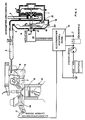
- the system according to the invention comprises a known evaporator pressure regulator 1, which has an inlet pipe 2 to connect the pressure regulator 1 to a container for a gaseous or liquid fuel, and a connecting pipe 3 for the outlet from the pressure regulator 1 of the vaporized fuel; on the connection pipe 3, a line 4 is fastened, which opens into a body 5 of a throttle valve upstream of a throttle valve 6;
- the air-fuel mixture is led through a suction line 7 into a combustion chamber 8 of the engine 9, in which it executes a working cycle.
- the exhaust gases exit from the combustion chamber 8 through an outlet 10.
- An oxygen sensor 11 (lambda probe) is screwed into the outlet 10 in order to analyze the oxygen concentration contained in the exhaust gases.
- the sensor 11 is electrically connected to an electronic control unit 12 in order to send an electrical signal to the control unit 12; in a known manner, a first and a second level of the signal each show a lean and a rich ratio of the air-fuel mixture.
- the control unit 12 is electrically connected to a drive 13 which has a slide 14; the drive 13 adjusts the slide 14 within a guide 15 from a first end stop A to a second end stop B and vice versa.
- the slide 14 is inserted in the line 4, therefore its movements proceed from the end stops A to the end stops B and vice versa in a direction which is perpendicular to the longitudinal axis of the line 4; if the slide 14 is in the end stops A, the area of the calibration cross section 16 of the gaseous fuel reaches its smallest value; If the slide 14 is in the end stops B, the area of the calibration cross section 16 reaches its greatest value.
- the slide 14 is suitable to be placed in any position, which is located between the end stops A and B, in order to change the area of the calibration cross section 16 in dependence on control signals which are sent by the control unit 12 are sent to the shoot 13; these control signals are processed on the basis of the first and the second level of the electrical signal coming from the sensor 11.
- the end stops A and B are adjustable to allow the correct regulation of the maximum and / or minimum flow of the fuel;
- known means are provided and not shown in FIGS. 1 and 2, which limit the respective end stops.
- An example of one of these means is shown in FIG. 5.
- the exemplary embodiment of the system shown in FIG. 2 differs from the exemplary embodiment shown in FIG. 1 only by a few components.
- the same reference numerals denote the same details; therefore we do not think it necessary to remember their name and arrangement in the system of Fig.2.
- the drive of the system shown in FIG. 2 has a rotor 17 which is driven by the drive 13 within the guide 15 in a first translation direction F 1 and in a second translation direction F 2, the translation directions F 1 and F 2 being perpendicular to the surface , which is limited by a membrane 18 of the second stage of the pressure regulator 1.
- a spring 19 is placed between the end of the rotor 17 and a plate 20 which solidifies the membrane 18; if the rotor 17 moves in the translation direction F 1, the membrane 18 increases its opening force for an outlet opening located between the first and the second stage of the pressure regulator 1 21; if the rotor 17 moves in the translation direction F2, the membrane 18 reduces its opening force for the outlet opening 21.
- the runner 17 is suitable to be placed in any position, which is between the outermost deflection in the translation direction F1 and the outermost deflection in the translation direction F2 to the force transmitted from the spring 19 to the membrane 18 depending on the to change control signals sent by the control unit 12 to the drive 13, which are processed on the basis of the first or the second level of the electrical signal coming from the sensor 11.
- end positions caused by the translations in the directions F1 and F2 are changeable to allow the correct regulation of the maximum and / or the minimum flow of the fuel;
- known means are provided and not shown in FIGS. 1 and 2, which limit the respective end stops.
- FIG. 3 shows a first exemplary embodiment of the drives 13; in this case the drive 13 consists of an electric motor 22 which is electrically connected to the control unit 12 in order to obtain control signals which determine the direction of rotation of a rotor 23.
- the rotor 23 is kinematically connected to a rod 24 by a known device which realizes the translations of the rod 24 in the directions of the arrows F3 and F4, while the rotor 23 rotates in the directions of the arrows F5 and F6, respectively.
- the rod 24 is kinematically connected to the slide 14 or to the rotor 17.
- FIG. 4 shows a second exemplary embodiment of the drive 13; in this case, the actuator 13 consists of a proportional solenoid valve 25 which is electrically connected to the control unit 12 in order to obtain control signals which determine the direction of translation of a movable armature 26 against the action of a spring 27.
- the armature 26 is kinematically connected to a rod 24 in order to drive the rod 24 in the directions of the arrows F7 and F9 depending on the current in the solenoid valve 25.
- the rod 24 is kinematically connected to the slide 14 or to the rotor 17.
- the item shown in Figure 5 relates to the line 4, which connects the pressure regulator 1 to the body 5; more precisely, the individual part relates to the calibration cross section 16 controlled by a slide 27.
- a rod 24 connects the slide 27 to a drive 13, which is similar to that shown in FIGS. 3 or 4.
- the slide 27 is partially supported within a guide bushing 28 which extends outside the line 4 and which has an axis of symmetry perpendicular to the line of symmetry of the line 4.
- the rod 24 passes through a hole provided in a plate 30; the plate 30 separates the line 4 from the interior 32 of a socket 33 carrying the drive 13 in order to protect the flow of the gaseous fuel from vortex movements which do not allow the flow of the gas through the line 4 to be monitored.
- a spring 31 clamps the plate 30 against an annular Surface 34, which is provided in the outer wall facing the interior 32.
- a regulating screw 29 is inserted in the interior of the guide bushing 28; the screw 29 has an axis of symmetry which coincides with the axis of symmetry of the socket 28.
- the tip of the screw 29 is suitable for stopping the movements of the slide 27 towards the inner space of the socket 28.
- the slide 27 reduces the area of the calibration cross section 16; If the drive 13 drives the slide 27 in the direction facing the interior of the bushing 28, the slide 27 increases the area of the calibration cross section 16.
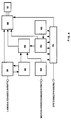
- FIG. 6 represents an electronic control unit 12 which can be used in any of the systems shown in FIGS. 1, 2 and 3.
- the following electrical circuits are essentially provided in the control unit 12:
- An adaptation and interface circuit 35 of the sensor 11 which is electrically connected to the sensor 11 in order to decode the levels of the respective electrical signal.
- the circuit 35 Based on the first level, the circuit 35 processes a first control signal for a control circuit 55 of the strut 13; on the basis of the second level, the circuit 35 processes a second control signal for the modulation circuit 55; for this purpose the circles 35 and 55 are electrical connected together.
- the first control signal causes the circuit 55 to control the drive 13 so that the rod 24 moves in the direction which enables the mixture supplied by the body 5 to be over-greased; the second control signal causes the circuit 55 to control the drive 13 so that the rod 24 moves in the direction which enables the mixture supplied by the body 5 to be depleted.
- An input and an output of the circuit 35 are electrically connected to a multiple timing circuit 40 so that the circuit 35 sends a signal to the circuit 40 indicating the operational readiness of the sensor 11.
- the operational readiness of the sensor 11 is determined by the district 40 at the end of a meaningless period. At the end of this time period, the transitions of the signal of the sensor 11 from the first to the second level clearly indicate that the sensor 11 is already in operation (namely that it has reached the operating temperature).
- the circuit 40 generates the periods of time that are necessary to allow the operation of the sensor 11.
- the circuit 40 stores the operational status of the sensor 11 and checks possible malfunctions or disassembly of the sensor 11 and / or the system by a test indicator, e.g. an LED connected to circuit 40.
- the circle 40 acts on the circle 35 during three successive periods T1, T2 and T3, which have expediently selected time period; the first period T1 begins when the ignition key closes.
- the circuit 40 sends a signal to the circuit 35 which makes it impossible for the circuit 35 to send the circuit 55 the first or the second control signal.
- the signal coming from the sensor 11 can have the first or the second level.
- the first level can indicate a lean titer of the mixture as well as a damage condition of the sensor 11 or the entire system (eg disassembly of the sensor 11, incorrect or damaged setting of the calibration devices of the system, etc.).
- the circuit 40 sends to the circuit 35 a signal which causes the circuit 35 to Circuit 55 to send the first or the second control signal, namely to control the drive 13.
- the circuit 40 sends to the circuit 35 a signal which permanently makes the circuit 35 incapable, to the circuit 55 the first or the second Send control signal.
- the circuit 40 sends to the circuit 35 at the end of the second period T2 a signal which causes the circuit 35 to the circuit 55 to send the first or the second control signal, namely to control the drive 13.
- the circuit 40 sends to the circuit 35 the signal which makes the circuit 35 unable to send to the circuit 55 the first or the second control signal; in addition, the circuit 40 activates the test vehicle to warn the driver of the damage to the system.
- switching the signal of the sensor 11 from the first to the second level, or vice versa allows the effect of the sensor 11 to be determined; in the case of switching, the circuit 40 causes the circuit 35 to send the first or the second control signal to the circuit 55, namely to control the drive 13 either at the end of the period T2 or in the course of the period T3.
- An output of the circuit 40 is connected to an input of a circuit 45 that generates reset and control clock signals.
- the circuit 45 is suitable for generating basic time signals during the reset phases when the ignition key is closed and during the control phase of the titer during regular operation of the engine.
- the circuit has 45 input circuits which stop the clock process when the sensor 11 is unusable or when the motor is in a damaged state (safety function).
- the control unit 12 comprises a reset and pre-regulation circuit 50 which ensures that the states of the drive 13 are zeroed when the ignition key is closed; the circuit therefore ensures 50 the pre-regulation of the titer by means of the drive 13 in the open-loop operating phases before the operational readiness of the 11 or in the event of damage to the same sensor.
- a first output of the circuit 50 is connected to an input of the circuit 45; a second output of the circuit 50 is connected to an input of the circuit 55.
- the control circuit 55 for the control of the drive 13 has inputs which are connected to the outputs of the circuits 35, 45 and 50. Means for controlling one of the drives used in the system are provided in the circuit 55.
- the control circuit 55 fulfills the task of decoding the signals of the direction and the speed of the movement of the drive 13 in order to ensure that the position of the drive 13 is reached, which is necessary for the correct monitoring of the titer of the mixture.
- a conditioning circuit 60 for conditioning a signal indicating the speed range of the engine is connected to the ignition coil.
- the processing circuit 60 processes the pulses occurring in the ignition coil and normalizes the signal coming from the ignition coil;
- the circuit 60 indicates a possible shutdown of the engine with the ignition key switched on in order to activate the safety circuits of the system.
- An output of the circuit 60 is connected to an input of the circuit 45.
- a pilot control circuit 65 is provided in the control unit 12, which pilot-controls the position of the drive 13 as a function of the temperature;
- the circuit 65 determines the various ambient temperature conditions of the system and the motor 9 and supplies various pre-regulation values for the drive 13 during the open-loop operating phase. Therefore, the circuit 65 is electrically connected to a temperature sensor and has an output connected to the circuit 55.
- the drive 13 consists of an electromechanical transducer, the purpose of which is to regulate the area of the calibration cross section 16 and the opening force transmitted to the membrane 18 as a function of the switching information from the circuit 55 in order to control the flow of the pressure regulator 1 to the Control body 5 delivered fuel.
- the drive can win 13 different designs. Examples of these designs are: a proportional solenoid valve, a fast solenoid valve with a variable working circuit, a stepper motor, a DC motor, etc.
- a sieve and regulator circuit 75 feeds the circuits of the control unit 12 and supplies the power levels that match the drive used.
- the circuit 75 generates timing settings for the ignition and the extinguishing which are used for the operation of the internal timings.
- the circle 75 is also connected to the individual circles of the control unit 12.
Landscapes
- Engineering & Computer Science (AREA)
- Chemical & Material Sciences (AREA)
- Combustion & Propulsion (AREA)
- Mechanical Engineering (AREA)
- General Engineering & Computer Science (AREA)
- Chemical Kinetics & Catalysis (AREA)
- General Chemical & Material Sciences (AREA)
- Oil, Petroleum & Natural Gas (AREA)
- Analytical Chemistry (AREA)
- Output Control And Ontrol Of Special Type Engine (AREA)
Description
Die vorliegende Erfindung betrifft eine Anlage zur Speisung eines Verbrennungsmotors mit einem gasfoermigen Brennstoff; die Anlage umfasst einen Verdampfer- Druckregler, eine zwischen dem Druckregler und einer Speisungsvorrichtung des Gemisches angeordnete Verbindungsleitung, einen im Auslass des Motors angeordneten Fuehler der Sauerstoffkonzentration, eine mit dem Fuehler elektrisch verbundene elektronische Kontrolleinheit und einen mit der Kontrolleinheit elektrisch verbundenen Trieb; wobei die Speisungsvorrichtung eine Drosselklappe aufweist, um den Durchfluss des Gemisches zu steuern. Der Trieb regelt den Durchfluss des Brennstoffes auf Grund von den vom Fuehler stammenden und durch die Kontrolleinheit berarbeiten Signalen.The present invention relates to a system for feeding an internal combustion engine with a gaseous fuel; the system comprises an evaporator pressure regulator, a connecting line arranged between the pressure regulator and a feed device of the mixture, a sensor of the oxygen concentration arranged in the outlet of the engine, an electronic control unit electrically connected to the sensor and an actuator electrically connected to the control unit; wherein the feed device has a throttle valve to control the flow of the mixture. The drive controls the flow of the fuel based on the signals from the sensor and revised by the control unit.
Aus dem Stand der Technik sind Speisungsanlagen fuer Verbrennungsmotoren bekannt, bei welchen im Auslass angeordnete Sauerstoff-Fuehler verwendet sind, um den Durchfluss des Brennstoffes in Abhaengigkeit von den Sauerstoffkonzentrationen zu aendern, wobei der Brennstoff von Vergasern oder Einspritzungsventilen geliefert ist.Feed systems for internal combustion engines are known from the prior art, in which oxygen sensors arranged in the outlet are used to change the flow of the fuel as a function of the oxygen concentrations, the fuel being supplied by carburetors or injection valves.
Den bekannten Anlagen liegen die Aufgaben zugrunde, die wesentlich davon abstammen, dass ein Fuehler eine vorbestimmte Betriebstemperatur erreichen soll, um elektrische Signale auszugeben, welche die wirklichen Sauerstoffkonzentrationen in den Abgasen anzeigen.
Liegt der Temperaturwert des Fuehlers unter dem Wert der Betriebstemperatur, so sind die vom Fuehler stammenden Signale nicht zuverlaessig; darum hat die Verarbeitung dieser Signale durch Elektro-nenrechner keine Bedeutung.The known systems are based on the tasks, which essentially derive from the fact that a sensor should reach a predetermined operating temperature in order to output electrical signals which indicate the actual oxygen concentrations in the exhaust gases.
If the temperature value of the sensor is below the value of the operating temperature, the signals coming from the sensor are not reliable; therefore the processing of these signals by electronic computers no meaning.
Ein Fuehler erreicht seine Betriebstemperatur waehrend des Warmlaufens des Motors; der erforderliche Zeitabstand zur Erreichung dieser Betriebstemperatur haengt von der Umgebungstemperatur und von der Auslaufzeit des Motors ab.A sensor reaches its operating temperature while the engine is warming up; the time interval required to reach this operating temperature depends on the ambient temperature and the stopping time of the motor.
FR-A-2 577 993 betrifft ein kontinuierliches Regulierungsverfahren zur Speisung eines Verbrennungsmotors mit gasförmigem Brennstoff sowie eine Vorrichtung zur Ausführung des Verfahrens.FR-A-2 577 993 relates to a continuous regulation method for supplying an internal combustion engine with gaseous fuel and a device for carrying out the method.
Das in dieser Unterlage beschriebene Verfahren darin besteht, daß,
- a- die Abgase durch eine λ-Sonde analysiert werden;
- b- die Signale der λ-Sonde an eine elektronische Kontrolleinheit übertragen werden;
- c- der Speisung des Motors durch die Kontrolleinheit kontrolliert wird
- a- the exhaust gases are analyzed by a λ probe;
- b- the signals of the λ probe are transmitted to an electronic control unit;
- c- the motor supply is controlled by the control unit
Das an einem Schrittmotor angeschlossene Drosselungsglied bewegt sich zwischen zwei Endanschlägen in Abhängigkeit von dem sigmoiden Signal der λ-Sonde zur Regelung des Durchflusses des zu dem Motor lieferden Brennstoffes.The throttling element connected to a stepper motor moves between two end stops depending on the sigmoid signal of the λ probe for regulating the flow of the fuel supplying the motor.
Dabei wird ein üblicher Computer mit einem internen Zeitgeber, einem Drehzahlsensorkreis und einem Temperatur-Sensor benützt, um wahrend des Starts bis zu einer bestimmten Temperatur die λ-Regelung zu verhindern.A common computer with an internal timer, a speed sensor circuit and a temperature sensor is used to prevent the λ regulation during the start up to a certain temperature.
In diesem wie in dem übrigen z.Z. vorliegenden Stand der Technik sind keine Steuerkreise vorgesehen, die die λ-Regelung bei festgestellten Fehlern unterbinden; auch die Einstellung der Endanschläge ist z.Z. aus dem vorliegenden Stand der Technik nicht entnehmbar.In this as in the rest of the time. In the present state of the art, no control circuits are provided which prevent the λ regulation in the event of detected errors; The setting of the end stops is currently also cannot be inferred from the present prior art.
Da sich der Temperatur-Sensor in dem Druckregler befindet, mißt er die nicht die Temperatur der λ-Sonde, sondern eine Temperatur, die den thermischen Zustand des Motors anzeigt. Deshalb bekommt die Kontrolleinheit kein Signal, das den Wirkungszustand des Fühlers bestätigt oder verneint.Since the temperature sensor is in the pressure regulator, he does not measure the temperature of the λ probe, but a temperature that indicates the thermal state of the engine. The control unit therefore does not receive a signal that confirms or denies the sensor's operating status.
Hier will die Erfindung Abhilfe schaffen.
Die Erfindung, wie sie in den Anspruechen gekennzeichnet ist, loest die Aufgabe, eine Regulierungsanlage mit Rueckeinwirkung des Titers des Luft-Kraftstoffgemisches zur Speisung eines Verbrennungsmotors, insbesonders eines mit gasfoermigem Brennstoff gespeisten Motors zu schaffen. Aus der Vervendung der Erfindung entstehet die Sperrung der Kontrolleinheit, so dass dieselbe Kontrolleinheit keine elektrischen Signale an den Trieb waehrend des Warmlaufens des Motors sendet, um eine Steuerung des Triebs auf Grund von nicht zuverlaessigen Signalen zu verhindern.The invention seeks to remedy this.
The invention, as characterized in the claims, solves the problem of creating a regulating system with back action of the titer of the air-fuel mixture for feeding an internal combustion engine, in particular an engine fed with gaseous fuel. The use of the invention results in the blocking of the control unit, so that the same control unit does not send any electrical signals to the drive while the engine is warming up, in order to prevent control of the drive on the basis of unreliable signals.
Die durch die Erfindung erreichten Vorteile sind im wesentlichen darin zu sehen, dass die Erstellung, die Installation und der Betrieb der Erfindung sehr billig sind.The advantages achieved by the invention can be seen essentially in the fact that the creation, installation and operation of the invention are very cheap.
In einer Ausführungsform umfaßt die erfindungsgemäße Anlage die folgenden Glieder:
einen mit einem Behälter für einen gasförmigen oder flüssigen Brennstoff verbundenen Verdampfer-Druckregler;
eine zwischen dem Druckregler und einem Körper eines Drosselventils angeordnete Leitung, um verdampften Brennstoff vom Druckregler an den Körper zu senden;
einen Verbrennungsmotor, der mit einer Ansaugleitung ausgestattet ist, um das Luft-Kraftstoffgemisch in eine Verbrennungskammer des Motors zu führen;
einen Auslaß für die Abgase aus der Verbrennungskammer;
einen innerhalb des Auslasses vorgesehenen Sauerstoff-Fühler (λ-Sonde), um die Sauerstoffkonzentration in den Abgasen zu analysieren;
eine elektronische Kontrolleinheit, die mit dem Fühler elektrisch verbunden ist, um ein elektrisches Signal vom Fühler zu bekommen, wobei ein erster und ein zweiter Pegel des Signals je ein mageres und ein fettes Verhältinis des Luft-Kraftstoffgemisches anzeigen, wobei die Kontrolleinheit mit einem Trieb elektrisch verbunden ist, der mit einem beweglichen Glied ausgestattet ist;
wobei der Trieb aus einem elektromechanischen Wandler besteht;
wobei das bewegliche Glied zwischen einem ersten Endanschlag und einem zweiten Endanschlag läuft und ein Eichungsorgan der Anlage betätigt, um den Durchfluß des vom Druckregler an den Körper gelieferten Brennstoffes zu steuern;
wobei Regulierungsmittel vorgesehen sind, die den ersten Endanschlag und/oder den zweiten Endanschlag begrenzen, um die richtige Regelung des maximalen oder minimalen Durchflusses des Brennstoffes zu erlangen;
wobei die Kontrolleinheit mit Steuerungskreisen ausgestattet ist, die die λ-Regelung bei festgestellten Fehlern des Fühlers und/oder der Anlage unterbinden.In one embodiment, the system according to the invention comprises the following elements:
an evaporator pressure regulator connected to a container for a gaseous or liquid fuel;
a conduit disposed between the pressure regulator and a body of a throttle valve for sending vaporized fuel from the pressure regulator to the body;
an internal combustion engine equipped with an intake pipe to lead the air-fuel mixture into a combustion chamber of the engine;
an outlet for the exhaust gases from the combustion chamber;
an oxygen sensor (λ probe) provided within the outlet to analyze the oxygen concentration in the exhaust gases;
an electronic control unit electrically connected to the sensor to receive an electrical signal from the sensor, a first and a second level of the signal indicating a lean and a rich ratio of the air-fuel mixture, the control unit being electrically driven connected, which is equipped with a movable member;
wherein the drive consists of an electromechanical transducer;
wherein the movable member runs between a first end stop and a second end stop and actuates a calibration element of the installation to control the flow of the fuel supplied to the body by the pressure regulator;
wherein regulating means are provided which limit the first end stop and / or the second end stop in order to to get the correct regulation of the maximum or minimum flow of fuel;
the control unit being equipped with control circuits which prevent the λ control in the event of detected faults in the sensor and / or the system.
Vorzugsweise sind die folgenden Vorrichtungen in der Anlage vorgesehen:
Dichtungsmittel zur Verhinderung des Eintritts des Gases von der Leitung oder vom Regler in den Trieb zwischen dem Trieb und der Leitung, wobei die Dichtungsmittel für den Schutz des Flusses des gasförmigen Kraftstoffes vor Wirbelbewegungen sorgen, die den Durchfluss des Gases durch die Leitung nicht überwachen lassen;
Verbindungsmittel, die die Dichtungsmittel zur Verbindung des Triebs mit einem Teil der Anlage durchqueren.The following devices are preferably provided in the system:
Sealing means for preventing the entry of the gas from the line or from the regulator into the drive between the drive and the line, the sealing means ensuring the flow of the gaseous fuel from swirling movements which do not allow the flow of the gas through the line to be monitored;
Lanyards that traverse the sealant to connect the drive to part of the system.
In wesentlichem umfaßt die Kontrolleinheit die folgenden Kreise:
einen Anpassungs-und-Schnittstellenkreis des Fühlers, der die Pegel des elektrischen Signals des Fühlers dekodiert;
einen Aussteuerungskreis des Triebs, der an dem Schnittstellenkreis angeschlossen ist, um von dem Schnittstellenkreis Steuerungssignale zu bekommen; die Steuerungssignale veranlassen der Aussteuerungskreis den Trieb so zu steurn, daß das bewegliche Glied das Eichungsorgan betätigt, um das Gemisch zu überfetten oder zu verarmen;
einen Zeitgebungskreis, der an dem Schnittstellenkreis angeschlossen ist, um vom Schnittstellenkreis ein Signal zu bekommen, das die Betriebsbereitschaft des Fühlers anzeigt.The control unit essentially comprises the following circles:
an adaptation and interface circuit of the sensor that decodes the levels of the electrical signal of the sensor;
a control circuit of the drive, which is connected to the interface circuit in order to receive control signals from the interface circuit; the control signals cause the modulation circuit to control the drive so that the movable member actuates the calibration element in order to over-grease or deplete the mixture;
a timing circuit connected to the interface circuit to receive a signal from the interface circuit get, which indicates the operational readiness of the sensor.
Weitere Vorteile, Einzelheiten und erfindungswesentliche Merkmale ergeben sich aus der nachfolgenden Beschreibung einer bevorzugten Ausführungsbeispiels der Anlage gemäß der Erfindung, unter bezugnahme auf die beigefügten Zeichnungen. Dabei zeigt im einzelnen:
- Figur 1
- eine skematich dargestellte Anlage nach einem ersten Ausfuehrungsbeispiel der Erfindung;
Figur 2- eine skematich dargestellte Anlage nach einem zweiten Ausfuehrungsbeispiel der Erfindung;
- Figur 3
- ein erstes Ausfuehrungsbeispiel des Triebs, der bei einer beliebigen der Anlagen der
Figuren 1, 2 oder 5 verwendet wird; - Figur 4
- ein zweites Ausfuehrungsbeispiel des Triebs, der bei einer beliebigen der Anlage der
Figuren 1, 2 oder 5 verwendet wird; Figur 5- einen Einzelteil der Anlage nach einem dritten Ausfuehrungsbeispiel der Erfindung;
Figur 6- ein Blockschaltbild der Kontrolleinheit, die bei einer beliebigen der Anlagen der
Figuren 1, 2 oder 5 verwendet wird.
- Figure 1
- a system shown schematically after a first Ausfuehrungsbeispiel the invention;
- Figure 2
- a system shown schematically according to a second exemplary embodiment of the invention;
- Figure 3
- a first exemplary embodiment of the drive, which is used in any of the systems of Figures 1, 2 or 5;
- Figure 4
- a second exemplary embodiment of the drive, which is used in any of the systems of Figures 1, 2 or 5;
- Figure 5
- an individual part of the system according to a third exemplary embodiment of the invention;
- Figure 6
- a block diagram of the control unit, which is used in any of the systems of Figures 1, 2 or 5.
Die Figuren stellen eine Regulierungsanlage mit Rueckeinwirkung des Titers des Luft-Kraftstoffgemisches zur Speisung eines Verbrennungsmotors, insbesonders eines mit gasfoermigem Brennstoff gespeisten Motors oder Einzelteilen der Anlage dar.The figures show a regulating system with back action of the titer of the air-fuel mixture for feeding an internal combustion engine, in particular an engine or individual parts of the system fed with gaseous fuel.
Gemaess Figur 1, umfasst die erfindungsmaessige Anlage einen bekannten Verdapfer-Druckregler 1, der ein Eingansgrohr 2 aufweist, um den Druckregler 1 mit einem Behaelter fuer einen gasfoermigen oder fluessigen Brennstoff zu verbinden, sowie ein Anschlussrohr 3 zum Ausgang vom Druckregler 1 des verdampften Brennstoffes; am Anschlussrohr 3 ist eine Leitung 4 befestigt, die in einen Koerper 5 eines Drosselventils stromauf einer Drosselklappe 6 muendet; durch eine Ansaugleitung 7 wird das Luft-Kraftstoffgemisch in eine Verbrennungskammer 8 des Motors 9 gefuehrt, in welcher es ein Arbeitkreislauf ausfuehrt. Die Abgase laufen aus der Verbrennungskammer 8 durch einen Auslass 10 aus. Ein Sauerstoff-Fuehler 11 (Lambda Sonde) ist innerhalb des Auslasses 10 eingeschraubt, um die in den Abgasen beinhaltete Sauerstoffkonzentration zu analysieren.According to FIG. 1, the system according to the invention comprises a known evaporator pressure regulator 1, which has an
Der Fuehler 11 ist mit einem elektronischen Kontrolleinheit 12 elektrisch verbunden, um an die Kontrolleinheit 12 ein elektrisches Signal zu senden; in bekannter Weise, zeigen ein erster und ein zweiter Pegel des Signals je ein mageres und ein Fettes Verhaeltnis des Luft-Kraftstoffgemisches. Die Kontrolleinheit 12 ist mit einem Trieb 13 elektrisch verbunden, der einen Schieber 14 aufweist; der Trieb 13 verstellt den Schieber 14 innerhalb einer Fuehrung 15 von einem ersten Endanschlage A zu einem zweiten Endanschlage B und umgekehrt. Der Schieber 14 ist in der Leitung 4 eingesetzt, darum gehen seine Bewegungen vom Endanschlage A zum Endanschlage B und umgekehrt in einer Richtung vor, die senkrecht auf der longitudinalen Achse der Leitung 4 ist; befindet sich der Schieber 14 im Endanschlage A, so erreicht der Flaecheninhalt des Eichungsquerschnittes 16 des gasfoermigen Brennstoffes seinen kleinsten Wert; befindet sich der Schieber 14 im Endanschlage B, so erreicht der Flaecheninhalt des Eichungsquerschnittes 16 seinen groessten Wert.The
Der Schieber 14 ist geeignet, in einer beliebigen Lage gestellt zu werden, die sich zwischen den Endanschlaegen A und B befindet, um den Flaecheninhalt des Eichungsquerschnittes 16 in Abhaengigkeit von Steuerungssignalen zu aendern, welche von der Kontrolleinheit 12 an den Trieb 13 gesandt werden; diese Steuerungssignale werden auf Grund von dem ersten und dem zweiten Pegel des elektrischen vom Fuehler 11 stammenden Signals verarbeitet.The
Die Endanschläge A und B sind verstellbar, um die richtige Regelung der maximalen und/oder der minimalen Durchflusses des Brennstoffes zu erlauben; zu diesem Zweck sind bekannte und in den Figuren 1 und 2 nicht dargestellte Mittel vorgesehen, welche die jeweiligen Endanschläge begrenzen. Ein Beispiel eines von diesen Mitteln ist in der Figur 5 dargestellt.The end stops A and B are adjustable to allow the correct regulation of the maximum and / or minimum flow of the fuel; For this purpose, known means are provided and not shown in FIGS. 1 and 2, which limit the respective end stops. An example of one of these means is shown in FIG. 5.
Das in der Figur 2 dargestellte Ausfuehrungsbeispiel der Anlage weicht vom in der Figur 1 dargestellten Ausfuehrungsbeispiel nur durch einige Bauelemente ab. In beiden Figuren bedeuten gleiche Bezugszeichen jeweils die gleichen Einzelheiten; daher meinen wir nicht noetig, ihre Bezeichnung und Anordnung in der Anlage der Fig.2 zu erinnern.The exemplary embodiment of the system shown in FIG. 2 differs from the exemplary embodiment shown in FIG. 1 only by a few components. In both figures, the same reference numerals denote the same details; therefore we do not think it necessary to remember their name and arrangement in the system of Fig.2.
Der Trieb der in der Fig.2 dargestellten Anlage weist einen Laeufer 17 auf, der durch den Trieb 13 innerhalb der Fuehrung 15 in einer ersten Translationsrichtung F₁ und in einer zweiter Translationsrichtung F₂ getrieben wird, wobei die Translationsrichtungen F₁ und F₂ senkrecht auf der Flache sind, die durch eine Membran 18 der zweiten Stufe des Druckreglers 1 begrenzt wird.The drive of the system shown in FIG. 2 has a
Eine Feder 19 ist zwischen dem Ende des Laeufers 17 und einer Platte 20 gelegt, die die Membran 18 erstarren laesst; bewegt sich der Lauefer 17 in der Translationsrichtung F₁, so verstaerkt die Membran 18 ihre Oeffnungskraft fuer eine zwischen der ersten und der zweiten Stufe des Druckreglers 1 sich befindliche Austrittsoeffnung 21; bewegt sich der Laeufer 17 in der Translationsrichtung F₂, so verkleinert die Membran 18 ihre Oeffnungskraft fuer die Austrittsoeffnung 21.A
Der Laeufer 17 ist geeignet, in einer beliebigen Stellung gestellt zu werden, die sich zwischen dem aeussersten Ausschlag in der Translationsrichtung F₁ und dem aeussersten Ausschlag in der Translationsrichtung F₂ befindet, um die von der Feder 19 an die Membran 18 uebergetragene Kraft in Abhaengigkeit von den von der Kontrolleinheit 12 an den Trieb 13 gesandten Steuerungssignalen zu veraendern, welche auf Grund von dem ersten oder dem zweiten Pegel des elektrischen vom Fuehler 11 stammenden Signals verarbeitet werden.The
Auch die durch die Translationen in den Richtungen F₁ und F₂ bewirkten Endstellungen sind veränderbar, um die richtige Regelung der maximalen und/oder der minimalen Durchflusses des Brennstoffes zu erlauben; zu diesem Zweck sind bekannte und in den Figuren 1 und 2 nicht dargestellte Mittel vorgesehen, welche die jeweiligen Endanschläge begrenzen.Also the end positions caused by the translations in the directions F₁ and F₂ are changeable to allow the correct regulation of the maximum and / or the minimum flow of the fuel; For this purpose, known means are provided and not shown in FIGS. 1 and 2, which limit the respective end stops.
Figur 3 stellt ein erstes Ausfuehrungsbeispiel des Triebe 13 dar; in diesem Fall besteht der Trieb 13 aus einem elektrischen Motor 22, der mit der Kontrolleinheit 12 elektrisch verbunden ist, um Steuerungssignale zu bekommen, die das Drehsinn eines Rotors 23 bestimmen. Der Rotor 23 ist mit einer Stange 24 durch eine bekannten Vorrichtung kinematisch verbunden, die die Translationen der Stange 24 in den Richtungen der Pfeile F₃ und F₄ verwirklicht, waehrend der Rotor 23 jeweilig in den Drehsinnen der Pfeile F₅ und F₆ drehet.FIG. 3 shows a first exemplary embodiment of the
Die Stange 24 ist mit dem Schieber 14 oder mit dem Laeufer 17 kinematisch verbunden.The
Figur 4 stellt ein zweites Ausfuehrungsbeispiel des Triebs 13 dar; in diesem Fall besteht der Trieb 13 aus einem proportionalen Solenoidventil 25, das mit der Kontrolleinheit 12 elektrisch verbunden ist, um Steuerungssignale zu bekommen, die die Translationsrichtung eines beweglichen Ankers 26 gegen die Wirkung einer Feder 27 bestimmen. Der Anker 26 ist mit einer Stange 24 kinematisch verbunden, um die Stange 24 in den Richtungen der Pfeile F₇ und F₉ in Abhaengigkeit von der Stromstaerke im Solienoidventil 25 zu treiben.FIG. 4 shows a second exemplary embodiment of the
Die Stange 24 ist mit dem Schieber 14 oder mit dem Laeufer 17 kinematisch verbunden.The
Der in der Figur 5 dargestellte Einzelteil betrifft die Leitung 4, die den Druckregler 1 mit dem Koerper 5 verbindet; genauer betrifft der Einzelteil den durch einem Schieber 27 gesteuerten Eichungsquerschnitt 16. Eine Stange 24 verbindet den Schieber 27 mit einem Trieb 13, der aehnlich wie jene ist, die in den Figuren 3 oder 4 dargestellt sind. Der Schieber 27 ist teilweise innerhalb einer Fuehrungsbuchse 28 gelagert, die sich ausser der Leitung 4 erstreckt und die eine senkrecht auf der Symmetrieachse der Leitung 4 Symmetrieachse aufweist. Die Stange 24 durchquert ein in einer Platte 30 vorgesehenes Loch; die Platte trennt 30 die Leitung 4 aus dem Innenraum 32 einer den Trieb 13 tragenden Buchse 33, um den Fluss des gasfoermigen Kraftstoffes vor Wirbelbewegungen zu schuetzen, die den Durchfluss des Gases durch die Leitung 4 nicht ueberwachen lassen. Eine Feder 31 spannt die Platte 30 gegen eine ringfoermige Flaeche 34, die in der nach dem Innenraum 32 gekehrten Aussenwand vorgesehen ist.The item shown in Figure 5 relates to the line 4, which connects the pressure regulator 1 to the
Eine Regulierschraube 29 ist im Innenraum der Fuehrungsbuchse 28 eingefuehrt; die Schraube 29 weist eine Symmetrieachse auf, die mit die Symmetrieachse der Buchse 28 zusammenfaellt. Die Spitze der Schraube 29 ist geeignet, die Bewegungen des Schiebers 27 nach dem Inneneraum der Buchse 28 zu stoppen.A regulating
Treibt der Trieb 13 den Schieber 27 in der dem Innenraum der Buchse 28 entgegensetzen Richtung, so vermindert der Schieber 27 den Flaecheninhalt des Eichungsquerschnittes 16; treibt der Trieb 13 den Schieber 27 in der dem Innenraum der Buchse 28 gekehrten Richtung, so vergroessert der Schieber 27 den Flaecheninhalt des Eichungsquerschnittes 16. Mit diesem Ausfuehrungsbeispiel ist es moeglich eine genaue Regelung des Durchflusses des gasfoermigen Brennstoffes zu erreichen, wenn man die Schraube 29 betaetigt.If the
Das Blockschaltbild der Fig.6 stellt eine elektronische Kontrolleinheit 12 dar, die in einer beliebigen der in den Figuren 1, 2 und 3 dargestellten Anlagen verwendbar ist. In wesentlichem sind die folgenden elektrischen Kreise in der Kontrolleinheit 12 vorgesehen:
Ein Anpassungs-und-Schnittstellekreis 35 des Fuehlers 11, der mit dem Fuehler 11 elektrisch verbunden ist, um die Pegel des jeweiligen elektrischen Signals zu dekodieren. Auf Grund vom ersten Pegel verarbeitet der Kreis 35 ein erstes Steuerungssignal fuer einen Aussteuerungskreis 55 des Trebs 13; auf Grund vom zweiten Pegel verarbeitet der Kreis 35 ein zweites Steuerungssignal fuehr den Aussteuerungskreis 55; dazu sind die Kreise 35 und 55 elektrisch zusammenverbunden. Das erste Steuerungssignal veranlaßt den Kreis 55 den Trieb 13 so zu steuern, dass die Stange 24 sich in der Richtung bewegt, die ermoeglicht, das vom Koerper 5 gelieferten Gemisch zu überfetten; das zweite Steuerungssignal veranlaßt den Kreis 55 den Trieb 13 so zu steuern, dass die Stange 24 sich in der Richtung bewegt, die ermoeglicht, des vom Koerper 5 gelieferten Gemisch zu verarmen.The block diagram of FIG. 6 represents an
An adaptation and
Ein Eingang und ein Ausgang des Kreises 35 sind mit einem Vielfachzeitgebungskreis 40 elektrisch so verbunden, dass der Kreis 35 an den Kreis 40 ein Signal sendet, das die Betriebsbereinschaft des Fuehlers 11 anzeigt. Die Betriebsbereinschaft des Fuehlers 11 wird durch den Kreis 40 am Ende eines bedeutungslosen Zeitraumes Festgestellt.
Am Ende dieses Zeitrauemes zeigen die Uebergaenge des Signals des Fuehlers 11 vom ersten zum zweiten Pegel eindeutig an, dass der Fuhler 11 schon in Betriebsbereinschaft ist (naemlich dass er die Betriebstemperatur erreicht hat).An input and an output of the
At the end of this time period, the transitions of the signal of the
Der Kreis 40 erzeugt die Zeitraeume die notwendig sind die Betriebsbereinaschaft des Fuehlers 11 zu erlauben. Der Kreis 40 speichert die Betriebsbereinschaft des Fuehlers 11 und prueft moegliche Missarbeitsweisen oder Zerlegen des Fuehlers 11 und/oder der Anlage durch einen Pruefanzeiger, z.B. eine LED, die mit dem Kreis 40 verbunden ist.The
Der Kreis 40 wirkt auf den Kreis 35 waehrend drei aufeinanderfolgender Zeitraeume T₁, T₂ und T₃, die zweckmaessig erwaehlte Zeitdauer aufweisen; der erste Zeitraum T₁ faengt beim Schliessen des Zuendschluessels an.
Im Laufe des ersten Zeitraumes T₁ ist der Fuehler 11 noch unverwendbar, darum sendet der Kreis 40 an den Kreis 35 ein Signal, das den Kreis 35 unfaehig macht, an den Kreis 55 das erste oder das zweite Steuerungssignal zu senden.
Im Laufe des zweiten Zeitraumes T₂ kann das vom Fuehler 11 stammende Signal den ersten oder den zweiten Pegel aufweisen. Der erste Pegel kann sowohl einen mageren Titer des Gemisches als auch einen Schadenzustand des Fuehlers 11 oder der ganzen Anlage bezeichen (z.B. Zerlegen des Fuehlers 11, unrichtige oder beschaedigte Einstellung der Eichungsvorrichtungen der Anlage u.s.w.).The
In the course of the first period T 1 the
In the course of the second period T₂, the signal coming from the
Falls das Signal des Fuehlers 11 sich am Anfang des ersten Zeitraumes T₁ im ersten Pegel befindt und, im Laufe des zweiten Zeitraumes T₂, zum zweiten Pegel umschalt, sendet der Kreis 40 an den Kreis 35 ein Signal, das den Kreis 35 veranlaßt, an den Kreis 55 das erste oder das zweite Steuerungssignal zu senden, naemlich den Trieb 13 zu steuern.If the signal of the
Falls das Signal des Fuehlers 11 sich im Laufe des Zeitrames T₂ im ersten Pegel befindet und zum zweiten Pegel nicht umschaltet, sendetder Kreis 40 an den Kreis 35 ein Signal, das den Kreis 35 andauernd unfaehig macht, an den Kreis 55 das erste oder das zweite Steuerungssignal zu senden.If the signal of the
Falls das Signal des Fuehlers 11 sich im Laufe des voelligen Zeitraumes T₂ im zweiten Pegel befindet, der einen fetten Titer des Gemisches anzeigt, sendet der Kreis 40 an den Kreis 35 am Ende des zweiten Zeitraumes T₂ ein Signal, das den Kreis 35 veranlaßt, an den Kreis 55 das erste oder das zweite Steuerungssignal zu senden, naemlich den Trieb 13 zu steuern.If the signal of the
Befindet sich das Signal des Fuehlers 11 im Laufe des ganzen Zeitraumes T₃ im ersten Pegel, so bedeutet das, dass die Anlage oder der Fuehler 11 beschaedigt sind; im diesem Fall sendet der Kreis 40 an den Kreis 35 das Signal, das den Kreis 35 unfaehig macht, an den Kreis 55 das erste oder das zweite Steuerungssignal zu senden; ausserdem aktiviert der Kreis 40 den Pruefanzelger, um den Fahrer vor dem Schaden der Anlage zu warnen.If the signal of the
Waehrend der Zeitraeume T₂ und T₃ erlaubt eine Umschaltung des Signals des Fuehlers 11 vom ersten zum zweiten Pegel, oder umgekehrt, den Wirkungsantritt des Fuehlers 11 festzustellen; im Umschaltungsfall veranlaßt der Kreis 40 den Kreis 35, an den Kreis 55 das erste oder das zweite Steuerungssignal zu senden, naemlich den Trieb 13 entweder am Ende des Zeitraumes T₂ oder im Laufe des Zeitraumes T₃ zu steuern.During the periods T₂ and T₃, switching the signal of the
Ein Ausgang des Kreises 40 steht in Verbindung mit einem Eingang eines Kreises 45, der Reset-und-Regelungsclocksignale erzeugt. Der Kreis 45 ist geeignet Grundzeitsignale waeherend der Resetphasen beim Schliessen des Zuendschluessels und waehrend der Regelungsphase des Titers bei regelmaessigem Betrieb des Motors zu erzeugen. Ausserdem weist der Kreis 45 Eingangschaltungen auf, die den Clockverlauf stoppen, wenn der Fuehler 11 unbrauchbar ist oder wenn der Motor in Schadenzustand ist (Sicherungsfunktion).An output of the
Die Kontrolleinhelt 12 umfasst einen Reset-und-Vorregelungskreis 50, der Fuer die Nulleinstellung der Zustaende des Triebs 13 beim Schliessen des Zuendschluessels sorgt; der Kreis gewährleistet 50 also die Vorregelung des Titers mittels des Triebs 13 bei den Open-Loopbetriebsphasen vor der Betriebsbereinschaft des Fuehlers 11 oder im Fall des Schadens desselben Fuehlers voranzusetzen. Ein erster Ausgang des Kreises 50 steht in Verbindung mit einem Eingang des Kreises 45; ein zweiter Ausgang des Kreises 50 steht in Verbindung mit einem Eingang des Kreises 55.The
Der Aussteuerungskreis 55 fuer die Steurung des Triebs 13 weist Eingaenge auf, die mit den Ausgaengen der Kreise 35, 45 und 50 in Verbindung stehen. Mittel zur Steuerung eines von den in der Anlage verwendeten Trieben sind im Kreis 55 vorgesehen.
Der Aussteuerungskreis 55 erfuellt die Aufgabe die Signale der Richtung und der Geschwindigkeit der Bewegung des Triebs 13 zu dekodieren, um die Erreichung der Lage des Triebs 13 zu gewaehrleisten, die zur richtigen Ueberwachung des Titers des Gemisches notwendig ist.The
The
Ein Aufbereitungs-Kreis 60 zur Aufbereitung eines den Drehzahlbereich des Motors anzeigenden Signals ist mit der Zündspule verbunden. Der Aufbereitungs-Kreis 60 verarbeitet die in der Zündspule anfallenden Impulse und normalisiert das von der Zündspule stammende Signal; außerdem zeigt der Kreis 60 eine mögliche Abstellung des Motors bei eingeschalter Zündschlüssel an, um die Sicherungsschaltungen der Anlage zu aktivieren. Ein Ausgang des Kreises 60 steht in Verbindung mit einem Eingang des Kreises 45.A
Ein Vorsteuer-Kreis 65 ist in der Kontrolleinheit 12 vorgesehen, der die Lage des Triebs 13 in Abhaengigkeit von der Temperatur vorsteuert; der Kreis 65 stellt die verschiedenen Umgebungstemperaturzustaende der Anlage und des Motors 9 fest und liefert verschiedene Vorregelungswerte fuer den Trieb 13 waehrend der Open-loop Betriebsphase. Darum ist der Kreis 65 mit einem Temperaturfuehler elektrisch verbunden und weist einen Ausgang auf, der in Verbindung mit dem Kreis 55 steht.
Der Trieb 13 besteht aus einem ein elektromechanischen Wandler, dessen Zweck darin bestehet, den Flaecheninhalt des Eichungsquerschnittes 16, sowie die an die Membran 18 uebergetragene Oeffnungskraft in Abhaengigkeit von der vom Kreis 55 stammenden Schaltinformationen zu regeln, um den Durchfluss des vom Druckregler 1 an den Koerper 5 gelieferten Brennstoffes zu steuern.A
The
Im Verhaeltnis zu der Verwendung und der Lage der Montage, kann der Trieb 13 verschiedene Gestaltungen gewinnen. Beispiele dieser Gestaltungen sind: ein proportionales Solenoidventil, ein schnelles Solenoidventil mit veraenderlichem Arbeitskreislauf, ein Schrittmotor, ein Gleichstrommotor, u.s.w.In relation to the use and location of the assembly, the drive can win 13 different designs. Examples of these designs are: a proportional solenoid valve, a fast solenoid valve with a variable working circuit, a stepper motor, a DC motor, etc.
Ein Sieb-und-Regulierungskreis 75 speist die Kreise der Kontrolleinhelt 12 und liefert die Leistungspegel, die zum verwendeten Trieb passen. Der Kreis 75 erzeugt zeitliche Einstellungen fuer die Zuendung und die Loeschung, die fuer den Betrieb den Innenzeitgebungen verwendet werden. Ausserdem steht der Kreis 75 in Verbindung mit den einzelnen Kreisen der Kontrolleinheit 12.A sieve and
Claims (8)
- Feedback control system of air/fuel ratio in internal combustion engines, especially in engines operating with gaseous fuel, which comprises the following elements:
a pressure regulator (1) connected to a tank for a liquid or gaseous fuel;
a pipe (4) between the regulator (1) and a throttle valve body (5) to send vaporised fuel from the regulator (1) to the body (5);
an engine (9) provided with an intake duct (7) to carry the air/fuel mixture to the combustion chamber (8) of the engine (9);
an exhaust duct (10) for the combustion gases, which come out of the combustion chamber (8);
an oxygen sensor (11) in the exhaust duct (10) to analyse the oxygen concentration in the combustion gases;
an electronic control unit (12) electrically connected to the sensor (11) to receive an electric signal from the sensor (11), a first and a second level of said signal representing, respectively, a lean or a rich mixture; the electronic control unit (12) being electrically connected to an actuator (13) provided with a movable element (14,17,24,27); the actuator (13) consisting of an electromechanical transducer;
the movable element (14,17,24,27) sliding between a first (A,F) and a second (B,F) stop position and acting on a calibration device (16,18) of the system to control the fuel amount sent by the regulator (1) to the throttle valve body (5);
characterised by the fact that regulation means are provided which delimit the first (A,F) and/or the second (B,F) stop position to obtain a right regulation of the highest and/or lowest amount of the fuel;
the control unit (12) being provided with circuits (40,45,50) which interrupt the λ-regulation in case of failure of the sensor (11) and/or the system. - System as in claim 1, characterised by the fact that it also includes sealing means (14,17,24,30) to prevent the gas coming out of the pipe (4) or the regulator (1) from entering the actuator (13); the sealing means (14,17,24,30) having the function of protecting the flow of fuel from vortical motions, which do not allow to control the gas amount through the pipe (4); connection means cross the sealing means (14,17,24,30) to connect the actuator (13) to a part (1,4) of the system.
- System as in claim 1, characterised by the fact that the following electrical circuits are provided in the electronic control unit (12):
an interface and decoding circuit (35) of the sensor (11), which decodes the levels of the electric signal of the sensor (11); according to the first level, the interface circuit (35) elaborating a first control signal for a pilot circuit (55) of the actuator (13), according to the second level the interface circuit (35) elaborating a second control signal for the pilot circuit (55); the first control signal enables the pilot circuit (55) to control the actuator (13) so that the movable element (14,17,24,27) acts the calibration device (16,18) to enrich the mixture; the second control signal enables the pilot circuit (55) to control the actuator (13) so that the movable element (14,17,24,27) acts the calibration device (16,18) to lean the mixture;
a timing circuit (40);
an inlet and an outlet of the interface circuit (35) are electrically connected to the timing circuit (40) so that the timing circuit (40) receives from the interface circuit (35) a signal, which points out the working of the sensor (11);
the timing circuit (40) provides the time intervals enabling the working of the sensor (11), in addition the timing circuit (40) stores the working state of the sensor (11) and valuates the possible failure of the sensor (11) and/or the system; if the sensor (11) is working, the timing circuit (40) sends the interface circuit (35) a signal which enables the interface circuit (35) to send the pilot circuit (55) the first or the second control signal; in case of failure of the sensor (11) or the system, the timing circuit (40) sends the interface circuit (35) a signal which prevents the interface circuit (35) from sending the pilot circuit (55) the first or the second control signal; in addition the timing circuit (40) acts a gauge;
a clock circuit (45), which provides clock signals for "reset" and "regulation";
the clock circuit (45) provides timing signals during the reset phases by closing the starting key and during the phase of regulation of the air/fuel ratio by normal running of the engine; in addition, the clock circuit (45) has inhibitory inlets which stop the progress of the clock in case there is something wrong with the sensor (11) or the system;
a "reset and preregulation" circuit connected to the pilot circuit (55) which sets the initial conditions of the actuator (13) by closing of the key and controls the regulation of the air/fuel ratio through the actuator (13) in the open-loop phases before the working of the sensor (11) or in case of failure of the same sensor (11);
a "set up" circuit (60) connected to spark coil, which sets up a signal which represents the angular speed of the engine (9); the set up circuit (60) processes and normalises the missing impulses in the spark coil; in addition the set up circuit (60) indicates an eventual stop of the engine (9) in case of inserted key to activate the safety circuits of the system;
a preregulation circuit (65) which preregulates the position of the actuator (13) according to the temperature; the preregulation circuit (65) is connected to the "Reset and preregulation" circuit (50) and identifies the various environmental conditions of the system and the engine (9) and supplies the various regulation values for the actuator (13) during the open-loop phases; the preregulation circuit (65) is electrically connected to a temperature sensor, a filtering and regulating circuit (75) which feeds the circuits of the unit (12) and supplies the various levels of power suitable for the employed actuator, the filtering and regulating circuit (75) supplies the time checking of ignition and extinction which are employed for the working of internal timing means. - System as in claim 3, characterised by the fact that the timing circuit (40) acts the interface circuit (35) during three following time periods (T₁,T₂,T₃), whose duration is duly chosen;
period (T₁) starts by closing the key; during period (T₁) the timing circuit (40) sends the interface circuit (35) the signal which prevents the interface circuit (35) from sending the pilot circuit (55) the first and the second control signal;
during period (T₂) and in case of non-switching of the signal of the sensor (11) from the first to the second level the timing circuit (40) sends the interface circuit (35) the signal which prevents the interface circuit (35) from sending the pilot circuit (55) the first an the second control signal; during period (T₂) and in case of switching of the signal of the sensor (11) from the first to the second level or of permanence of the same signal in the second level the timing circuit (40) sends the interface circuit (35) the signal which enables the interface circuit (35) to send the pilot circuit (55) the first an the second control signal;
in case of permanence of the signal of the sensor (11) in the first level during the whole period (T₃) the timing circuit (40) sends the interface circuit (35) the signal which prevents the interface circuit (35) from sending the pilot circuit (55) the first an the second control signal; in addition it acts a gauge to inform the driver about a failure of the system;
if during period (T₃) the signal of the sensor (11) remains at the second level or switches from first to second level, the timing circuit (40) sends the interface the signal which enables the interface circuit (35) to send the pilot circuit (55) the first and the second control signal. - System as in claims 1 and 2, characterised by the fact that the movable element (14,17,24,27) is an obturator (27) mechanically connected to the actuator (13) by a rod (24) and that the calibration device (16) is a transversal section (16) of the pipe (4), a part of the obturator (27) being inserted in a guiding bushing (28) which develops in the external part of the pipe (4) and presents an axis of symmetry perpendicular to the axis of symmetry of the pipe (4); a plate (30) separating the pipe (4) from an internal part (32) of a bushing (33) which supports the actuator (13); the plate (30) having a hole (4) crossed by the rod (24).
- System as in claim 5, characterised by the fact that an adjusting screw (29) is inserted in the internal part of the bushing (28); the adjusting screw (29) having an axis of symmetry which coincides with the axis of symmetry of the bushing (33); the point of the adjusting screw (29) stopping the movements of the obturator (27) in the direction of the internal part of the bushing (28).
- System as in claims 1 and 2, characterised by the fact that the movable element (14,17,24,27) is an an obturator (14) mechanically connected to the actuator (13) by a rod (24) and that the calibration device (16) is a transversal section (16) of the pipe (4); the actuator (13) placing the obturator (14) in a position which is between a first adjustable position (A) and a second adjustable position (B) to vary the area of the calibration section (16) according to the regulation signals sent by the unit (12) to the actuator (13); the regulation signals being processed according to the first or the second level of the electrical signal supplied by sensor (11).
- System as in claims 1 and 2, characterised by the fact that the movable element (14,17,24,27) is a slider (17) mechanically connected to the actuator by a rod (24) and that the calibration device (16) is a diaphragm (18) of the second stage of the regulator (1), a spring (19) being inserted between the end of the slider (17) and a plate (20) which stiffs the diaphragm (18); if slider (17) moves to a first direction (F₁) the diaphragm (18) increases the opening force which opens an orifice (21) between the first and second stage of the regulator (1); if slider (17) moves to a second direction (F₂) the diaphragm (18) decreases said opening force; the slider (17) is capable of being placed in any position between the limit stop in the direction (F₁) and the limit stop in the direction (F₂) to vary the force transmitted by the spring (19) to the diaphragm (18) according to the regulation signals sent by the unit (19) to the actuator (13); the regulation signals being processed according to the first or second level of the electrical signal provided by sensor (11).
Priority Applications (2)
| Application Number | Priority Date | Filing Date | Title |
|---|---|---|---|
| DE90108144T DE59004697D1 (en) | 1990-04-28 | 1990-04-28 | Regulation system with reaction of the titer of the air-fuel mixture for feeding an internal combustion engine, in particular an engine fed with gaseous fuel. |
| EP90108144A EP0454875B1 (en) | 1990-04-28 | 1990-04-28 | Feedback control system of air/fuel ratio in internal combustion engines, especially in engines operating with gaseous fuel |
Applications Claiming Priority (1)
| Application Number | Priority Date | Filing Date | Title |
|---|---|---|---|
| EP90108144A EP0454875B1 (en) | 1990-04-28 | 1990-04-28 | Feedback control system of air/fuel ratio in internal combustion engines, especially in engines operating with gaseous fuel |
Publications (2)
| Publication Number | Publication Date |
|---|---|
| EP0454875A1 EP0454875A1 (en) | 1991-11-06 |
| EP0454875B1 true EP0454875B1 (en) | 1994-02-23 |
Family
ID=8203936
Family Applications (1)
| Application Number | Title | Priority Date | Filing Date |
|---|---|---|---|
| EP90108144A Expired - Lifetime EP0454875B1 (en) | 1990-04-28 | 1990-04-28 | Feedback control system of air/fuel ratio in internal combustion engines, especially in engines operating with gaseous fuel |
Country Status (2)
| Country | Link |
|---|---|
| EP (1) | EP0454875B1 (en) |
| DE (1) | DE59004697D1 (en) |
Families Citing this family (4)
| Publication number | Priority date | Publication date | Assignee | Title |
|---|---|---|---|---|
| ZA939334B (en) * | 1992-12-14 | 1994-10-03 | Transcom Gas Tecnologies Pty L | Engine control unit |
| US5390651A (en) * | 1993-10-29 | 1995-02-21 | Precision Engine Controls Corporation | Air/fuel ratio controller for larger internal combustion engines |
| IT1302629B1 (en) * | 1998-10-08 | 2000-09-29 | Landi Renzo Spa | FEEDING, IMPLEMENTATION AND CONTROL SYSTEM OF A GAS INJECTION FUEL ENGINE. |
| JP5841925B2 (en) * | 2012-09-21 | 2016-01-13 | ヤンマー株式会社 | Internal combustion engine |
Family Cites Families (3)
| Publication number | Priority date | Publication date | Assignee | Title |
|---|---|---|---|---|
| JPS5623549A (en) * | 1979-08-02 | 1981-03-05 | Fuji Heavy Ind Ltd | Air-fuel ratio controller |
| JPS5751935A (en) * | 1980-09-12 | 1982-03-27 | Nippon Denso Co Ltd | Air-to-fuel return controller |
| FR2577993B1 (en) * | 1985-02-22 | 1989-06-16 | Totalgaz Cie Fse | METHOD FOR THE CONTINUOUS REGULATION OF THE SUPPLY OF AN ENGINE WITH FUEL IN THE GAS STATE AND DEVICE IMPLEMENTING SAID METHOD |
-
1990
- 1990-04-28 EP EP90108144A patent/EP0454875B1/en not_active Expired - Lifetime
- 1990-04-28 DE DE90108144T patent/DE59004697D1/en not_active Expired - Fee Related
Also Published As
| Publication number | Publication date |
|---|---|
| EP0454875A1 (en) | 1991-11-06 |
| DE59004697D1 (en) | 1994-03-31 |
Similar Documents
| Publication | Publication Date | Title |
|---|---|---|
| DE2245029C3 (en) | Method and device for exhaust gas decontamination from internal combustion engines | |
| DE2553678C3 (en) | Control device for the composition of an air / fuel mixture fed to an internal combustion engine | |
| EP0039932B1 (en) | Gas proportion control device for an anaesthetising apparatus | |
| EP2324291A2 (en) | Security system in and method for operating an internal combustion system | |
| WO1995035440A2 (en) | Throttle valve device | |
| DE3642404A1 (en) | MIXING RATIO CONTROL SYSTEM FOR MOTOR VEHICLE ENGINES | |
| DE2847794C2 (en) | Fuel injection system for the internal combustion engine of a motor vehicle | |
| EP0624721B1 (en) | Method to discriminate between fault sources in a system for controlling the mixture fed to an internal combustion engine | |
| DE2604689A1 (en) | ELECTRONIC CONTROL DEVICE FOR SUPPLYING THE OPTIMAL FUEL-AIR MIXTURE | |
| DE3230211C2 (en) | ||
| DE10303252B4 (en) | Control device for an internal combustion engine with a variable valve train for changing the opening and closing characteristics of the intake valve and / or exhaust valve | |
| EP2021602A1 (en) | Modular fuel supply device for a gas turbine | |
| EP0454875B1 (en) | Feedback control system of air/fuel ratio in internal combustion engines, especially in engines operating with gaseous fuel | |
| DE3048386C2 (en) | Carburetor with a mixture enrichment system | |
| DE3200096C2 (en) | ||
| DE19706382A1 (en) | Procedure for testing for correctly connected lambda probes | |
| DE3739805C3 (en) | Device for regulating the speed of an internal combustion engine | |
| DE3011523C2 (en) | Air-fuel ratio control arrangement for an internal combustion engine | |
| DE4036844A1 (en) | METHOD AND DEVICE FOR CONTROLLING AN IDLE CONTROL VALVE OF AN INTERNAL COMBUSTION ENGINE | |
| DE3409050C2 (en) | ||
| DE3029313A1 (en) | SYSTEM FOR REGULATING THE AIR FUEL RATIO OF AN INTERNAL COMBUSTION ENGINE | |
| DE4410735A1 (en) | Asynchronous motor speed control, esp. for combustion applications | |
| DE3921011C2 (en) | ||
| DE3151111C2 (en) | Arrangement for regulating the air-fuel ratio of an internal combustion engine | |
| DE19918851A1 (en) | Stepper motor control device for idling speed control valve in internal combustion engine |
Legal Events
| Date | Code | Title | Description |
|---|---|---|---|
| PUAI | Public reference made under article 153(3) epc to a published international application that has entered the european phase |
Free format text: ORIGINAL CODE: 0009012 |
|
| AK | Designated contracting states |
Kind code of ref document: A1 Designated state(s): AT BE CH DE DK ES FR GB GR IT LI LU NL SE |
|
| RBV | Designated contracting states (corrected) |
Designated state(s): BE DE FR IT NL |
|
| 17P | Request for examination filed |
Effective date: 19920424 |
|
| 17Q | First examination report despatched |
Effective date: 19920805 |
|
| RAP1 | Party data changed (applicant data changed or rights of an application transferred) |
Owner name: B.B. S.R.L. |
|
| GRAA | (expected) grant |
Free format text: ORIGINAL CODE: 0009210 |
|
| AK | Designated contracting states |
Kind code of ref document: B1 Designated state(s): BE DE FR IT NL |
|
| ITF | It: translation for a ep patent filed |
Owner name: STUDIO BREV. NAZIONALI ED ESTERI |
|
| REF | Corresponds to: |
Ref document number: 59004697 Country of ref document: DE Date of ref document: 19940331 |
|
| ET | Fr: translation filed | ||
| PLBE | No opposition filed within time limit |
Free format text: ORIGINAL CODE: 0009261 |
|
| STAA | Information on the status of an ep patent application or granted ep patent |
Free format text: STATUS: NO OPPOSITION FILED WITHIN TIME LIMIT |
|
| 26N | No opposition filed | ||
| NLS | Nl: assignments of ep-patents |
Owner name: LOTUS CARS LIMITED |
|
| REG | Reference to a national code |
Ref country code: FR Ref legal event code: TP |
|
| PGFP | Annual fee paid to national office [announced via postgrant information from national office to epo] |
Ref country code: BE Payment date: 19990421 Year of fee payment: 10 |
|
| PGFP | Annual fee paid to national office [announced via postgrant information from national office to epo] |
Ref country code: NL Payment date: 19990429 Year of fee payment: 10 Ref country code: FR Payment date: 19990429 Year of fee payment: 10 |
|
| PGFP | Annual fee paid to national office [announced via postgrant information from national office to epo] |
Ref country code: DE Payment date: 19990630 Year of fee payment: 10 |
|
| PG25 | Lapsed in a contracting state [announced via postgrant information from national office to epo] |
Ref country code: BE Free format text: LAPSE BECAUSE OF NON-PAYMENT OF DUE FEES Effective date: 20000430 |
|
| BERE | Be: lapsed |
Owner name: LOTUS CARS LTD Effective date: 20000430 |
|
| PG25 | Lapsed in a contracting state [announced via postgrant information from national office to epo] |
Ref country code: NL Free format text: LAPSE BECAUSE OF NON-PAYMENT OF DUE FEES Effective date: 20001101 |
|
| PG25 | Lapsed in a contracting state [announced via postgrant information from national office to epo] |
Ref country code: FR Free format text: LAPSE BECAUSE OF NON-PAYMENT OF DUE FEES Effective date: 20001229 |
|
| NLV4 | Nl: lapsed or anulled due to non-payment of the annual fee |
Effective date: 20001101 |
|
| PG25 | Lapsed in a contracting state [announced via postgrant information from national office to epo] |
Ref country code: DE Free format text: LAPSE BECAUSE OF NON-PAYMENT OF DUE FEES Effective date: 20010201 |
|
| REG | Reference to a national code |
Ref country code: FR Ref legal event code: ST |
|
| PG25 | Lapsed in a contracting state [announced via postgrant information from national office to epo] |
Ref country code: IT Free format text: LAPSE BECAUSE OF NON-PAYMENT OF DUE FEES;WARNING: LAPSES OF ITALIAN PATENTS WITH EFFECTIVE DATE BEFORE 2007 MAY HAVE OCCURRED AT ANY TIME BEFORE 2007. THE CORRECT EFFECTIVE DATE MAY BE DIFFERENT FROM THE ONE RECORDED. Effective date: 20050428 |