EP0454415B1 - Portable printers - Google Patents
Portable printers Download PDFInfo
- Publication number
- EP0454415B1 EP0454415B1 EP91303638A EP91303638A EP0454415B1 EP 0454415 B1 EP0454415 B1 EP 0454415B1 EP 91303638 A EP91303638 A EP 91303638A EP 91303638 A EP91303638 A EP 91303638A EP 0454415 B1 EP0454415 B1 EP 0454415B1
- Authority
- EP
- European Patent Office
- Prior art keywords
- printer
- printing unit
- printing
- unit
- housing
- Prior art date
- Legal status (The legal status is an assumption and is not a legal conclusion. Google has not performed a legal analysis and makes no representation as to the accuracy of the status listed.)
- Expired - Lifetime
Links
- 238000007639 printing Methods 0.000 claims abstract description 56
- 239000000758 substrate Substances 0.000 claims abstract description 20
- 230000001681 protective effect Effects 0.000 claims abstract description 6
- 239000002184 metal Substances 0.000 claims description 23
- 238000012546 transfer Methods 0.000 claims description 22
- 230000006870 function Effects 0.000 claims description 17
- 230000001154 acute effect Effects 0.000 claims description 2
- 229920003023 plastic Polymers 0.000 description 7
- 239000004033 plastic Substances 0.000 description 7
- 229910000831 Steel Inorganic materials 0.000 description 4
- 239000000463 material Substances 0.000 description 4
- 239000010959 steel Substances 0.000 description 4
- 238000010276 construction Methods 0.000 description 2
- 238000013459 approach Methods 0.000 description 1
- 210000000078 claw Anatomy 0.000 description 1
- 238000013461 design Methods 0.000 description 1
- 239000003814 drug Substances 0.000 description 1
- 230000000694 effects Effects 0.000 description 1
- 238000003780 insertion Methods 0.000 description 1
- 230000037431 insertion Effects 0.000 description 1
- 238000012423 maintenance Methods 0.000 description 1
- 238000004519 manufacturing process Methods 0.000 description 1
- 230000009993 protective function Effects 0.000 description 1
- 238000007651 thermal printing Methods 0.000 description 1
- 238000010023 transfer printing Methods 0.000 description 1
- 238000009423 ventilation Methods 0.000 description 1
Images


Classifications
-
- B—PERFORMING OPERATIONS; TRANSPORTING
- B41—PRINTING; LINING MACHINES; TYPEWRITERS; STAMPS
- B41J—TYPEWRITERS; SELECTIVE PRINTING MECHANISMS, i.e. MECHANISMS PRINTING OTHERWISE THAN FROM A FORME; CORRECTION OF TYPOGRAPHICAL ERRORS
- B41J3/00—Typewriters or selective printing or marking mechanisms characterised by the purpose for which they are constructed
- B41J3/36—Typewriters or selective printing or marking mechanisms characterised by the purpose for which they are constructed for portability, i.e. hand-held printers or laptop printers
Definitions
- This invention relates to portable printers.
- Portable printers are widely used in a variety of environments including retail stores, hospitals, laboratories and goods handling facilities. Often they are used to print bar codes which serve as identity tags for the articles to which they are attached. Portable printers are to be distinguished from hand-held printers which, although easily carried, have special constructional features (such as a hand grip) to enable them to function (i.e. to perform the steps of printing, dispensing and applying a label) while held in the hand of an operative.
- hand-held printers which, although easily carried, have special constructional features (such as a hand grip) to enable them to function (i.e. to perform the steps of printing, dispensing and applying a label) while held in the hand of an operative.
- Bar codes are particularly useful because they facilitate the use of fully automatic in-and-out systems and, in some instances, do away with the need for price labels on products offered for sale.
- bar codes are useful in a variety of areas including patient identification, specimen collection an distribution, distribution of valuable commodities such as pharmaceuticals, and document tracking; equally, they are useful in management applications, e.g. accounting, supplies management, time recording/allocating and tracking of personnel and of documents.
- label printers In order to apply labels to articles which are required to carry a bar code identification, it is common to use one or more label printers. These may be hand-held, portable or fixed in position. Typically, a supermarket will employ three stationary printers which will be utilised by up to ten people. Other places of use, e.g. laboratories, may have just a single fixed printer. Strips or labels will be printed and taken to the product or article to be labelled and either applied by hand or by means of a label dispenser. An alternative to the use of a fixed printer is to use a hand-held printer.
- Portable printers have much more capacity and versatility than hand-held printers, since they are less susceptible to design constraints imported by the need to maintain minimum size and comfortable hand usage. They are also more convenient to use compared to fixed printers, since they can be carried to the point of use.
- a portable printer which comprises a housing; a printing unit including a printing zone through which (in use) a substrate onto which indicia are to be printed is passed; means for supplying said substrate to said printing unit; and means for inputting data to control the nature of the indicia printed at said printing unit, characterised in that said housing includes a main frame which serves to support the functional components of the printer; a protective casing which fits over said frame; and a front cover removably attached to the remainder of the housing, the inside face of said cover supporting or containing a keyboard or keypad which constitutes or forms a component of said means for inputting data.
- the printing unit may take the form of an ink jet print unit; or a thermographic print unit; or a thermal transfer print unit.
- the portable printer has a multi-mode print unit.
- the main frame is a sheet metal frame, e.g. a steel frame.
- the protective housing preferably has a front housing part and a rear housing part which are secured together about the main frame of the printer.
- the keyboard or keypad is alphanumeric.
- the printing unit may be arranged so that it can operate in a direct, thermal print mode and in an indirect, thermal transfer mode.
- the printing unit may be pivotally mounted so as to be movable from a second, inoperative position to a first, operative position in which the print head abuts the printing zone; and the frame may include a front plate positioned substantially perpendicular to the printing zone and having a slot located so as to be positioned at the printing zone when the printing unit is in the second, inoperative position, whereby a thermal transfer ribbon may be inserted through said slot into the printing zone.
- Embodiments which utilise a printing ribbon advantageously have means for supplying the substrate to the printing unit which means comprises at least one spool or spool holder which is arranged so that, when the printer is placed on a flat, horizontal surface, the at least one spool or spool holder is oriented at an acute angle to the vertical, thereby assisting in retaining a spool containing a roll of substrate in place.
- the printer is arranged so that its components are mounted on a framework which defines the desired orientation: this orientation is advantageously in the range 5 o to 25 o from the vertical.
- the functional components of the printer in accordance with all aspects of the invention are carried on a sheet metal frame.
- this main frame also carries a pair of flanges which in turn support a spindle on which the printer handle is mounted.
- the central metal frame is preferably located inside inner and outer housing components which conveniently are fabricated from a plastics material. These housing parts may be screwed together through recesses in the central metal frame.
- the rear housing unit includes a horizontal ledge on both sides onto which the lower part of the metal frame seats.
- a main logic board may be located beneath the metal frame and may be fixed to the frame, e.g. by three screws.
- the front and rear housing parts in preferred embodiments of this invention have no support function nor any locating function so far as the functional components of the printer are concerned.
- the only locating function is that mentioned above, namely the provision of flanges near the bottom edge on the inside of the rear housing component onto which the main metal frame is located.
- the central metal frame is preferably disposed so that its main support surface is oriented at an angle of 15 o the vertical.
- the preferred structure described above has several advantages. Firstly, it is easy to assemble all of the functional components on the metal frame on a production line. Secondly, maintenance of the working parts of the printer is easy. Thirdly, the plastics housing is able to provide a proper protective function, since it does not support any of the functional units of the printer.
- the power supply for the printer is separated as between the logic components on the one hand, and the print head on the other; this twin supply arrangement gives more stable operating voltages.
- the central metal frame has semi-circular cut-outs near its upper edge, through which parts of the rear housing unit pass. These parts function as receiving elements for screws which serve to join the front and rear housing units together. The screw receiving elements also help to locate the central metal frame at its upper end.
- a dismountable rear door may be hingedly attached to the rear housing component to give access to the power supply section of the printer. Beneath this door, there is preferably a rectangular port which allows access for computer interfacing of the printer; and a power supply input connector for recharging the batteries. Ventilation slots are preferably provided in the top and bottom of the rear housing units.
- the computer interface permits the printer to be operated without any input from its own keyboard.
- the handle is secured to a spindle mounted in the top part of the main metal frame.
- the spindle may be located between a pair of forwardly projecting flanges at the top of the metal frame.
- the handle is conveniently mounted on the spindle by means of plastic rings.
- the spindle preferably also carries a spring-loaded rectangular metal flap which functions as a retaining clip for the keyboard.
- the keyboard is hinged onto the lower front part of the front housing unit.
- a recessed, projecting portion along the horizontal axis of the front housing unit cooperates with a correspondingly shaped recess in the bottom edge of the keyboard unit.
- This recess in the keyboard unit includes two inwardly projecting metal cylinders at opposite sides of the recess.
- One of these metal cylinders functions as the cable inlet port for the keyboard. Both metal cylinders act as locating elements when the keyboard is fitted to the front housing unit. Once this fitment is effected, a plastic locking element may be fitted over the junction.
- the locking element in the embodiment under consideration comprises a plastics strip having a pair of downwardly projecting lugs at opposite ends, these lugs serving to locate about the metal cylinders in the keyboard recess.
- the locking strip also includes a pair of longer plastic lugs locating inwardly of the first-mentioned lugs, and these longer lugs clip into the recessed section of the front housing. This arrangement provides a robust hinge which nevertheless can be easily dismantled.
- the printer is provided with a plurality of sensors which provide a number of control functions.
- the printer contains six sensors, but it will be understood that the printer of this invention is not limited to a construction containing any or all of these sensors, or only these sensors.
- the six presently preferred sensors are as follows:
- a single stepping motor is preferably used to drive the printer.
- the drive arrangement adopted in one embodiment of the printer is as follows: A circular-sectioned drive band connects the output of the stepping motor to a slipping clutch drive for rewinding the backing paper from a web of labels. A toothed belt passes from the output of the stepping motor to the print roller at the output end of the print unit. A further circular sectioned drive band connects the print roller to a slipping clutch drive which serves to rewind the transfer ribbon within its cassette. This fits into a slot in the lower right-hand side of the front housing unit.
- the print head unit is preferably modular and is constructed so that it can be removed as a unit from the metal frame.
- the battery or batteries which are conveniently located in a power supply module carried by the rear face of the central metal frame of the printer, are preferably of a type which can be recharged from an outside power source, e.g. via a DIN-type socket provided at the rear of the printer.
- the battery charging operation is preferably under microprocessor control to give proper voltage and current; a sensor such as the thermistor mentioned earlier preferably ensures that the battery does not overheat during this operation.
- a printer in accordance with the present invention is provided with means whereby it can operate in conjunction with a memory card or a "smart card".
- a slot for receiving such a card can conveniently be provided on the front of the printer.
- the printer 1 comprises a housing 2 made up of a front housing part 2a and a rear housing part 2b (see Fig. 5). Parts 2a and 2b are held together by screws which pass through channels formed in the lower part of each housing part.
- the two housing parts are carried by a steel frame 2c which also serves to support all of the functional components of the printer, as will be described hereinafter.
- the front housing part 2a supports a face 3 of which is in the form of cover hingedly attached at 4 to the lower front section of housing part 2a.
- the inner face of cover 3 comprises an alphanumeric keyboard 5 which includes a plurality of keys such as 6a, 6b, 6c etc.
- a carrying handle 7 is provided on the top of the housing.
- the base 8 of the housing is adapted to stand on a flat surface.
- the main components on the front of the printing unit are oriented or disposed so that the notional axis 9 of these components makes an angle of about 15 o with the vertical.
- the printer includes a printing unit 16 including a print head 17.
- the print head 17 co-operates with a roller 18 to define a nip through which a substrate to be printed is passed.
- the zone through which the substrate passes defines a printing zone 19.
- a substrate (e.g. a label carried on a roll of backing material) is wound as a spool 10 carried on a spool holder 11.
- Spent backing material is collected on a take-up spool 12 carried on spool holder 13.
- Lines 14, 14a and 15 show the path of the substrate from spool 10 to printing unit 16.
- Lines 20 and 20a show the path of the spent backing material from the roller 18 to take-up spool 12.
- a roller 21 is provided to guide the incoming substrate into the printing unit 16.
- a platen 22 also serves to support the incoming substrate.
- a first sensor a serves to detect the presence of a substrate in the approach to printing zone 19.
- Sensor a is constructed as a fork, one arm of which is located on each side of the substrate path.
- One of the arms carries a miniature light source, and the other arm a photodetector (not shown); the output of the photodetector changes when the light beam is intercepted by the presence of substrate.
- the illustrated printer 1 is adapted to function both as a direct thermal printer, in which heated elements in the print head 17 act on a thermally sensitive substrate to generate the desired indicia; and also as an indirect, thermal transfer printer, in which the heated elements of the print head 17 serve to cause a transfer of a medium such as ink from a transfer ribbon.
- the printer is adapted to function with an ink transfer ribbon cassette 30. This has a supply spool 31 which co-operates with a spool holder 32 mounted on the printer; and a take-up spool 33 which co-operates with spool holder 34 mounted on the printer.
- Lines 35, 35a, 36 and 36a show the travel of a cassette ribbon from spool 31, through printing unit 16 and back to take-up spool 33.
- the cassette 30 has arms or 'claws' 37 and 38 which terminate in rollers 39 and 40, respectively, over which the ink transfer ribbon passes on entering and leaving the cassette.
- An ink ribbon sensor b is provided to detect the presence of an ink ribbon in the vicinity of printing zone 19.
- Detector b is of the infra red reflection type, having an infra red emitter and detector side by side on a support.
- a microswitch d is also provided on the frame behind ribbon cassette 30 to give an indication of the presence or absence of a cassette.
- Printing unit 16 is pivotally mounted to the frame 2c by pivot 42. This allows the printing unit to travel between a first, operative position (as seen in Figure 1) where the print head 17 presses the ribbon 35, 35a and the substrate 14, 14a onto the roller 18 and a second, inoperative position where the print head 17 is held away from the roller 18, which facilitates servicing and/or replacing the print head, should this be required.
- a microswitch sensor e gives an indication of the position of the printing unit.
- Platen 22 is attached to the frame 2c by screws 41.
- the printing unit 16 includes a front plate 43 having a slot 44 which coincides with the location of printing zone 19 when the printing unit 16 is in its first operative position (as seen in Figure 1). Slot 44 enables the ready replacement of an ink transfer ribbon cassette 30 if the print head 17 is held in the second, inoperative position away from the roller 18.
- the parts 11, 13, 16, 18, 21, 32 and 34 are all attached to and supported by the steel frame 2c.
- a drive motor 60 is also mounted on the frame 2c.
- the printer also includes a display panel 50 which may comprise an LCD or a series of LEDs.
- the display may be divided into a plurality of separate characters such as 51a, 51b, ....52a, 52b.... etc., as seen in Figure 2.
- a slot 45 is provided on the right hand side at the front of the printer (see Fig. 2); this slot serves to receive a memory card or "smart card" which may, for example, contain control data for the printer.
- an output guide table 46 is detachably mounted at the output end of printing zone 19.
- the printing regime can be selected so as to print a continuous run of, for example, labels; alternatively the printer can operate to produce individual labels one by one.
- a label feed sensor c (see Figure 1) is located close to output guide table 46; sensor c detects the presence or absence of a label on the table 46 so that, when a single printed label is removed, the sensor output serves to actuate the printing of the next label.
- the frame 2c comprises a main section 70, a base section 71 and a foot section 72.
- Main section 70 extends upwardly from base section 72 making an angle ⁇ of 75 o so that the section 72 is oriented at 15 o to the vertical.
- a pair of forwardly extending flanges 80 (of which one can be seen in Figure 6) is secured to the upper part of frame section 70 and serves to receive handle 7.
- a rearwardly extending upper flange 73 attached to section 70 cooperates with an upwardly extending flange 74 attached to base section 71 to support a printed circuit board 90.
- Section 70 also carries a downwardly extending plate 75 to which a bracket 76 is bolted at 77; bracket 76 serves to retain a power supply module 91 which is seated against base section 71 of the frame 2c.
Landscapes
- Accessory Devices And Overall Control Thereof (AREA)
- Printers Characterized By Their Purpose (AREA)
- Steroid Compounds (AREA)
- Gyroscopes (AREA)
- Liquid Crystal Substances (AREA)
- Photographic Developing Apparatuses (AREA)
- Developing Agents For Electrophotography (AREA)
- Hydrogenated Pyridines (AREA)
Abstract
Description
- This invention relates to portable printers.
- Portable printers are widely used in a variety of environments including retail stores, hospitals, laboratories and goods handling facilities. Often they are used to print bar codes which serve as identity tags for the articles to which they are attached. Portable printers are to be distinguished from hand-held printers which, although easily carried, have special constructional features (such as a hand grip) to enable them to function (i.e. to perform the steps of printing, dispensing and applying a label) while held in the hand of an operative.
- Bar codes are particularly useful because they facilitate the use of fully automatic in-and-out systems and, in some instances, do away with the need for price labels on products offered for sale.
- In medical and scientific applications, bar codes are useful in a variety of areas including patient identification, specimen collection an distribution, distribution of valuable commodities such as pharmaceuticals, and document tracking; equally, they are useful in management applications, e.g. accounting, supplies management, time recording/allocating and tracking of personnel and of documents.
- In order to apply labels to articles which are required to carry a bar code identification, it is common to use one or more label printers. These may be hand-held, portable or fixed in position. Typically, a supermarket will employ three stationary printers which will be utilised by up to ten people. Other places of use, e.g. laboratories, may have just a single fixed printer. Strips or labels will be printed and taken to the product or article to be labelled and either applied by hand or by means of a label dispenser. An alternative to the use of a fixed printer is to use a hand-held printer.
- Portable printers have much more capacity and versatility than hand-held printers, since they are less susceptible to design constraints imported by the need to maintain minimum size and comfortable hand usage. They are also more convenient to use compared to fixed printers, since they can be carried to the point of use.
- According to one aspect of the present invention, there is provided a portable printer which comprises a housing; a printing unit including a printing zone through which (in use) a substrate onto which indicia are to be printed is passed; means for supplying said substrate to said printing unit; and means for inputting data to control the nature of the indicia printed at said printing unit, characterised in that said housing includes a main frame which serves to support the functional components of the printer; a protective casing which fits over said frame; and a front cover removably attached to the remainder of the housing, the inside face of said cover supporting or containing a keyboard or keypad which constitutes or forms a component of said means for inputting data.
- In the various embodiments described herein, the printing unit may take the form of an ink jet print unit; or a thermographic print unit; or a thermal transfer print unit. In several advantageous embodiments, the portable printer has a multi-mode print unit.
- Preferably, the main frame is a sheet metal frame, e.g. a steel frame. The protective housing preferably has a front housing part and a rear housing part which are secured together about the main frame of the printer.
- Advantageously, the keyboard or keypad is alphanumeric.
- In certain embodiments, the printing unit may be arranged so that it can operate in a direct, thermal print mode and in an indirect, thermal transfer mode.
- Furthermore, the printing unit may be pivotally mounted so as to be movable from a second, inoperative position to a first, operative position in which the print head abuts the printing zone; and the frame may include a front plate positioned substantially perpendicular to the printing zone and having a slot located so as to be positioned at the printing zone when the printing unit is in the second, inoperative position, whereby a thermal transfer ribbon may be inserted through said slot into the printing zone.
- Embodiments which utilise a printing ribbon advantageously have means for supplying the substrate to the printing unit which means comprises at least one spool or spool holder which is arranged so that, when the printer is placed on a flat, horizontal surface, the at least one spool or spool holder is oriented at an acute angle to the vertical, thereby assisting in retaining a spool containing a roll of substrate in place.
- Preferably, the printer is arranged so that its components are mounted on a framework which defines the desired orientation: this orientation is advantageously in the
range 5o to 25o from the vertical. - Preferably the functional components of the printer in accordance with all aspects of the invention are carried on a sheet metal frame. Preferably, this main frame also carries a pair of flanges which in turn support a spindle on which the printer handle is mounted. The central metal frame is preferably located inside inner and outer housing components which conveniently are fabricated from a plastics material. These housing parts may be screwed together through recesses in the central metal frame. Advantageously, the rear housing unit includes a horizontal ledge on both sides onto which the lower part of the metal frame seats. A main logic board may be located beneath the metal frame and may be fixed to the frame, e.g. by three screws. Significantly, the front and rear housing parts in preferred embodiments of this invention have no support function nor any locating function so far as the functional components of the printer are concerned. The only locating function is that mentioned above, namely the provision of flanges near the bottom edge on the inside of the rear housing component onto which the main metal frame is located. The central metal frame is preferably disposed so that its main support surface is oriented at an angle of 15o the vertical.
- The preferred structure described above has several advantages. Firstly, it is easy to assemble all of the functional components on the metal frame on a production line. Secondly, maintenance of the working parts of the printer is easy. Thirdly, the plastics housing is able to provide a proper protective function, since it does not support any of the functional units of the printer.
- Preferably, the power supply for the printer is separated as between the logic components on the one hand, and the print head on the other; this twin supply arrangement gives more stable operating voltages.
- Advantageously, the central metal frame has semi-circular cut-outs near its upper edge, through which parts of the rear housing unit pass. These parts function as receiving elements for screws which serve to join the front and rear housing units together. The screw receiving elements also help to locate the central metal frame at its upper end.
- A dismountable rear door may be hingedly attached to the rear housing component to give access to the power supply section of the printer. Beneath this door, there is preferably a rectangular port which allows access for computer interfacing of the printer; and a power supply input connector for recharging the batteries. Ventilation slots are preferably provided in the top and bottom of the rear housing units. The computer interface permits the printer to be operated without any input from its own keyboard.
- As mentioned above in connection with the general structure of the printer, the handle is secured to a spindle mounted in the top part of the main metal frame. The spindle may be located between a pair of forwardly projecting flanges at the top of the metal frame. The handle is conveniently mounted on the spindle by means of plastic rings. The spindle preferably also carries a spring-loaded rectangular metal flap which functions as a retaining clip for the keyboard.
- In preferred embodiments, the keyboard is hinged onto the lower front part of the front housing unit. In one embodiment, a recessed, projecting portion along the horizontal axis of the front housing unit cooperates with a correspondingly shaped recess in the bottom edge of the keyboard unit. This recess in the keyboard unit includes two inwardly projecting metal cylinders at opposite sides of the recess. One of these metal cylinders functions as the cable inlet port for the keyboard. Both metal cylinders act as locating elements when the keyboard is fitted to the front housing unit. Once this fitment is effected, a plastic locking element may be fitted over the junction. The locking element in the embodiment under consideration comprises a plastics strip having a pair of downwardly projecting lugs at opposite ends, these lugs serving to locate about the metal cylinders in the keyboard recess. The locking strip also includes a pair of longer plastic lugs locating inwardly of the first-mentioned lugs, and these longer lugs clip into the recessed section of the front housing. This arrangement provides a robust hinge which nevertheless can be easily dismantled.
- Preferably, the printer is provided with a plurality of sensors which provide a number of control functions. In the presently preferred arrangement, the printer contains six sensors, but it will be understood that the printer of this invention is not limited to a construction containing any or all of these sensors, or only these sensors. The six presently preferred sensors are as follows:
- (1) Paper Sensor.
This may be a fork-type in which the existence of paper serves to intercept a beam which would otherwise pass from its transmitter to a receiver (photodetector). - (2) Transfer ribbon detector.
This may be an infrared transmit/receive sensor mounted with the beam and detector side-by-side. This sensor and the paper detector are preferably mounted on a small plastic bracket which is secured to the main metal frame of the printer. - (3) Single label feed sensor.
This may be the same in construction as the transfer ribbon detector, mentioned above. It is located at the outlet end of the printer, and detects removal of a single label when the printer is in the single label mode. Removal of a label from a table at the print unit outlet is detected and the detector then actuates the printing of the next label, with its associated label feed functions. - (4) Transfer cassette detector.
This is preferably a microswitch fitted to the central metal frame in the region where a transfer ribbon cassette would be mounted; insertion of such a cassette actuates the microswitch, which then sets the printing parameters (e.g. power supply to the print head) appropriately. Normally, lower power is required for transfer printing as opposed to direct thermal printing. - (5) Print head position detector.
A microswitch may be used to detect whether or not the print head is in its operative or inoperative position. - (6) Battery temperature thermistor.
This detects the temperature of the power supply battery during recharge. The thermistor may be mounted adjacent to the battery pack. It is used to control the recharging current during battery recharge in order to optimise the recharge operation. - A single stepping motor, advantageously one having 200 steps, is preferably used to drive the printer. The drive arrangement adopted in one embodiment of the printer is as follows:
A circular-sectioned drive band connects the output of the stepping motor to a slipping clutch drive for rewinding the backing paper from a web of labels. A toothed belt passes from the output of the stepping motor to the print roller at the output end of the print unit. A further circular sectioned drive band connects the print roller to a slipping clutch drive which serves to rewind the transfer ribbon within its cassette.
This fits into a slot in the lower right-hand side of the front housing unit. - The print head unit is preferably modular and is constructed so that it can be removed as a unit from the metal frame.
- The battery or batteries, which are conveniently located in a power supply module carried by the rear face of the central metal frame of the printer, are preferably of a type which can be recharged from an outside power source, e.g. via a DIN-type socket provided at the rear of the printer. The battery charging operation is preferably under microprocessor control to give proper voltage and current; a sensor such as the thermistor mentioned earlier preferably ensures that the battery does not overheat during this operation.
- Advantageously, a printer in accordance with the present invention is provided with means whereby it can operate in conjunction with a memory card or a "smart card". A slot for receiving such a card can conveniently be provided on the front of the printer.
- For a better understanding of the invention, and to show how the same may be carried into effect, reference will now be made, by way of example, to the accompanying drawings, in which:
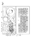
- FIGURE 1 is a schematic front elevational view showing the printing unit and some of the associated parts of a printer in accordance with this invention;
- FIGURE 2 is a front elevational view of the exterior of the printer of Figure 1;
- FIGURE 3 is a side elevational cut-away view corresponding to Figure 2;
- FIGURE 4 is a view corresponding to that of Figure 3 but with the front cover of the printer opened;
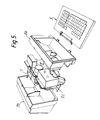
- FIGURE 5 is an exploded view showing the structural framework and the housing of the printer; and
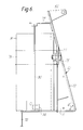
- FIGURE 6 is a side view of part of the framework shown in Figure 5.
- Referring now to the drawings, the
printer 1 comprises ahousing 2 made up of afront housing part 2a and arear housing part 2b (see Fig. 5).Parts steel frame 2c which also serves to support all of the functional components of the printer, as will be described hereinafter. Thefront housing part 2a supports a face 3 of which is in the form of cover hingedly attached at 4 to the lower front section ofhousing part 2a. The inner face of cover 3 comprises analphanumeric keyboard 5 which includes a plurality of keys such as 6a, 6b, 6c etc. A carryinghandle 7 is provided on the top of the housing. Thebase 8 of the housing is adapted to stand on a flat surface. - As can be seen in Figure 3, the main components on the front of the printing unit are oriented or disposed so that the
notional axis 9 of these components makes an angle of about 15o with the vertical. - As seen in Figures 1 and 4, where the cover 3 is in its opened position, thereby giving access to the
keyboard 5, the printer includes aprinting unit 16 including aprint head 17. Theprint head 17 co-operates with aroller 18 to define a nip through which a substrate to be printed is passed. The zone through which the substrate passes defines aprinting zone 19. - A substrate (e.g. a label carried on a roll of backing material) is wound as a
spool 10 carried on a spool holder 11. Spent backing material is collected on a take-upspool 12 carried onspool holder 13.Lines spool 10 toprinting unit 16.Lines 20 and 20a show the path of the spent backing material from theroller 18 to take-upspool 12. Aroller 21 is provided to guide the incoming substrate into theprinting unit 16. Aplaten 22 also serves to support the incoming substrate. - A first sensor a serves to detect the presence of a substrate in the approach to
printing zone 19. Sensor a is constructed as a fork, one arm of which is located on each side of the substrate path. One of the arms carries a miniature light source, and the other arm a photodetector (not shown); the output of the photodetector changes when the light beam is intercepted by the presence of substrate. - The illustrated
printer 1 is adapted to function both as a direct thermal printer, in which heated elements in theprint head 17 act on a thermally sensitive substrate to generate the desired indicia; and also as an indirect, thermal transfer printer, in which the heated elements of theprint head 17 serve to cause a transfer of a medium such as ink from a transfer ribbon. To this end, the printer is adapted to function with an inktransfer ribbon cassette 30. This has asupply spool 31 which co-operates with aspool holder 32 mounted on the printer; and a take-upspool 33 which co-operates withspool holder 34 mounted on the printer.Lines 35, 35a, 36 and 36a show the travel of a cassette ribbon fromspool 31, throughprinting unit 16 and back to take-upspool 33. Thecassette 30 has arms or 'claws' 37 and 38 which terminate inrollers 39 and 40, respectively, over which the ink transfer ribbon passes on entering and leaving the cassette. - An ink ribbon sensor b is provided to detect the presence of an ink ribbon in the vicinity of
printing zone 19. Detector b is of the infra red reflection type, having an infra red emitter and detector side by side on a support. A microswitch d is also provided on the frame behindribbon cassette 30 to give an indication of the presence or absence of a cassette. -
Printing unit 16 is pivotally mounted to theframe 2c bypivot 42. This allows the printing unit to travel between a first, operative position (as seen in Figure 1) where theprint head 17 presses the ribbon 35, 35a and thesubstrate roller 18 and a second, inoperative position where theprint head 17 is held away from theroller 18, which facilitates servicing and/or replacing the print head, should this be required. A microswitch sensor e gives an indication of the position of the printing unit. -
Platen 22 is attached to theframe 2c by screws 41. - As can be seen best from Figure 2, the
printing unit 16 includes afront plate 43 having aslot 44 which coincides with the location of printingzone 19 when theprinting unit 16 is in its first operative position (as seen in Figure 1).Slot 44 enables the ready replacement of an inktransfer ribbon cassette 30 if theprint head 17 is held in the second, inoperative position away from theroller 18. - The
parts steel frame 2c. Adrive motor 60 is also mounted on theframe 2c. - The printer also includes a
display panel 50 which may comprise an LCD or a series of LEDs. The display may be divided into a plurality of separate characters such as 51a, 51b, ....52a, 52b.... etc., as seen in Figure 2. - A
slot 45 is provided on the right hand side at the front of the printer (see Fig. 2); this slot serves to receive a memory card or "smart card" which may, for example, contain control data for the printer. - As shown in Figure 5, an output guide table 46 is detachably mounted at the output end of
printing zone 19. - The printing regime can be selected so as to print a continuous run of, for example, labels; alternatively the printer can operate to produce individual labels one by one. For the latter, a label feed sensor c (see Figure 1) is located close to output guide table 46; sensor c detects the presence or absence of a label on the table 46 so that, when a single printed label is removed, the sensor output serves to actuate the printing of the next label.
- Referring next to Figure 6, the
steel frame 2c is shown, but without depicting any of thecomponents frame 2c comprises amain section 70, abase section 71 and afoot section 72.Main section 70 extends upwardly frombase section 72 making an angle Θ of 75o so that thesection 72 is oriented at 15o to the vertical. A pair of forwardly extending flanges 80 (of which one can be seen in Figure 6) is secured to the upper part offrame section 70 and serves to receivehandle 7. A rearwardly extendingupper flange 73 attached tosection 70 cooperates with an upwardly extendingflange 74 attached tobase section 71 to support a printedcircuit board 90.Section 70 also carries a downwardly extendingplate 75 to which abracket 76 is bolted at 77;bracket 76 serves to retain apower supply module 91 which is seated againstbase section 71 of theframe 2c.
Claims (25)
- A portable printer (1) which comprises a housing (2); a printing unit (16) including a printing zone (19) through which (in use) a substrate (14,14a) onto which indicia are to be printed is passed; means for supplying said substrate to said printing unit; and means for inputting data to control the nature of the indicia printed at said printing unit, wherein said housing includes a main frame (2c) which serves to support the functional components of the printer; a protective casing (2a,2b) which fits over said frame; and a front cover (3) removably attached to the remainder of the housing, the inside face of said cover supporting or containing a keyboard or keypad (5) which constitutes or forms a component of said means for inputting data.
- A printer as claimed in claim 1, characterised in that said main frame (2c) is a sheet metal frame.
- A printer as claimed in claim 1 or 2, characterised in that said protective casing comprises a front part (2a) and a rear part (2b) both of which are secured together about the main frame (2c) of the printer.
- A printer as claimed in claim 3, characterised in that said front and rear parts (2a,2b) function as protective members without serving to support functional components of the printer.
- A printer as claimed in claim 1, 2, 3 or 4, characterised in that said main frame (2c) comprises a substantially laminar support member (70) which is oriented at an angle of from 5 to 25 degrees from the vertical.
- A printer as claimed in claim 5, characterised in that said laminar support member (70) is oriented at an angle of about 15 degrees to the vertical.
- A printer as claimed in any preceding claim, characterised in that said keyboard or keypad (5) is alphanumeric.
- A printer as claimed in any preceding claim, characterised in that said data inputting means further comprises a memory card.
- A printer as claimed in any preceding claim, characterised in that said printing unit (16) is an ink jet printer.
- A printer as claimed in any one of claims 1 to 8, characterized in that said printing unit (16) is a thermographic print unit.
- A printer as claimed in any one of claims 1 to 8, characterised in that said printing unit (16) is a thermal transfer print unit.
- A printer as claimed in any one of claims 1 to 8, characterised in that said printing unit (16) is arranged so that it can operate in a direct, thermal print mode and in an indirect, thermal transfer mode.
- A printer as claimed in claim 11 or 12, characterized in that said printing unit (16):(i) is pivotally mounted so as to be movable from a second, inoperative position to a first, operative position in which the print head (17) abuts said printing zone (19); and(ii) said frame (2c) includes a front plate (43) positioned substantially perpendicular to said printing zone (19) and having a slot (44) located so as to be positioned at the printing zone (19) when the printing unit (16) is in said second, inoperative position, whereby a thermal transfer ribbon (35,35a) may be inserted through said slot into the printing zone.
- A printer as claimed in claim 11 or 12, characterised in that said means for supplying the substrate (14,14a) to said printing unit (16) comprises at least one spool (31) or spool holder (32) which is arranged so that, when the printer (1) is placed on a flat, horizontal surface, said at least one spool or spool holder is oriented at an acute angle to the vertical, thereby assisting in retaining a spool containing a roll of substrate in place.
- A printer as claimed in any preceding claim, characterised in that the power supply (91) for the printer is in two parts, one part providing power for the logic components (90) and the other part providing power for the print head (17).
- A printer as claimed in any preceding claim, characterised in that a main logic board (90) is located beneath the main frame (2c) of the printer (1).
- A printer as claimed in any preceding claim, characterised in that said keyboard (5) is hingedly attached to the lower front part of the printer housing (2).
- A printer as claimed in any preceding claim, characterised in that the printer (1) includes a paper sensor (a) which functions to detect the presence of paper onto which indicia are to be printed.
- A printer as claimed in any preceding claim, characterised in that the printer (1) includes a transfer ribbon detector (b) which functions to detect the presence of an ink transfer ribbon (35,35a) in the printer.
- A printer as claimed in any preceding claim, characterised in that the printer (1) includes a label dispensing sensor (c) which functions to detect the removal of a single label from the outlet (46) of the printer and to actuate the printing of a further label in response to such removal.
- A printer as claimed in any preceding claim, characterised in that the printer (1) includes a transfer cassette detector (d) which functions to detect the presence, in the printer, of a transfer ribbon cassette (30) and which serves to adjust the operating parameters of the printer so as to be suitable for functioning in an ink transfer mode.
- A printer as claimed in any preceding claim, characterised in that the printer (1) includes a print head position detector (e) which functions to detect whether the print head (17) is in the operative or inoperative position.
- A printer as claimed in any preceding claim, characterised in that the printer includes a sensor for detecting the temperature of an electrical battery forming part of the power supply system (91) for the printer.
- A printer as claimed in any preceding claim, characterised in that the print head (17) is a modular unit which can be removed from the main frame (2c) of the printer (1) as a unit.
- A printer as claimed in any one of claims 1 to 8 and 14, characterised in that said printing unit (16) is a multi-mode printing unit.
Applications Claiming Priority (2)
| Application Number | Priority Date | Filing Date | Title |
|---|---|---|---|
| GB9009157 | 1990-04-24 | ||
| GB9009157A GB2243336A (en) | 1990-04-24 | 1990-04-24 | Portable printers. |
Publications (3)
| Publication Number | Publication Date |
|---|---|
| EP0454415A2 EP0454415A2 (en) | 1991-10-30 |
| EP0454415A3 EP0454415A3 (en) | 1992-02-26 |
| EP0454415B1 true EP0454415B1 (en) | 1995-01-18 |
Family
ID=10674890
Family Applications (1)
| Application Number | Title | Priority Date | Filing Date |
|---|---|---|---|
| EP91303638A Expired - Lifetime EP0454415B1 (en) | 1990-04-24 | 1991-04-23 | Portable printers |
Country Status (8)
| Country | Link |
|---|---|
| US (1) | US5344248A (en) |
| EP (1) | EP0454415B1 (en) |
| JP (1) | JPH04226378A (en) |
| AT (1) | ATE117244T1 (en) |
| DE (1) | DE69106768T2 (en) |
| ES (1) | ES2067860T3 (en) |
| GB (1) | GB2243336A (en) |
| SG (1) | SG30611G (en) |
Families Citing this family (55)
| Publication number | Priority date | Publication date | Assignee | Title |
|---|---|---|---|---|
| JP2991596B2 (en) * | 1993-09-03 | 1999-12-20 | キヤノン株式会社 | Recording device |
| US5707162A (en) * | 1993-11-24 | 1998-01-13 | Seiko Epson Corporation | Modular information processing apparatus |
| JP3399051B2 (en) * | 1993-11-24 | 2003-04-21 | セイコーエプソン株式会社 | POS terminal and its printing device |
| GB9512148D0 (en) * | 1995-06-15 | 1995-08-16 | Esselte Dymo Nv | Tape printing apparatus |
| US6786420B1 (en) | 1997-07-15 | 2004-09-07 | Silverbrook Research Pty. Ltd. | Data distribution mechanism in the form of ink dots on cards |
| US6618117B2 (en) | 1997-07-12 | 2003-09-09 | Silverbrook Research Pty Ltd | Image sensing apparatus including a microcontroller |
| US6879341B1 (en) | 1997-07-15 | 2005-04-12 | Silverbrook Research Pty Ltd | Digital camera system containing a VLIW vector processor |
| US6690419B1 (en) | 1997-07-15 | 2004-02-10 | Silverbrook Research Pty Ltd | Utilising eye detection methods for image processing in a digital image camera |
| US6624848B1 (en) | 1997-07-15 | 2003-09-23 | Silverbrook Research Pty Ltd | Cascading image modification using multiple digital cameras incorporating image processing |
| US7110024B1 (en) | 1997-07-15 | 2006-09-19 | Silverbrook Research Pty Ltd | Digital camera system having motion deblurring means |
| US6948794B2 (en) | 1997-07-15 | 2005-09-27 | Silverbrook Reserach Pty Ltd | Printhead re-capping assembly for a print and demand digital camera system |
| DE19832093A1 (en) * | 1997-08-22 | 1999-02-25 | Esselte Nv | Tape printing device |
| US6579020B2 (en) * | 1998-01-12 | 2003-06-17 | Easyprint A/S | Thermal printer |
| US6607318B2 (en) * | 1998-01-12 | 2003-08-19 | Easyprint A/S | Thermal printer |
| AUPP702098A0 (en) | 1998-11-09 | 1998-12-03 | Silverbrook Research Pty Ltd | Image creation method and apparatus (ART73) |
| AUPP702198A0 (en) * | 1998-11-09 | 1998-12-03 | Silverbrook Research Pty Ltd | Image creation method and apparatus (ART79) |
| US7042478B2 (en) * | 1999-03-26 | 2006-05-09 | Datamax Corporation | Modular printer |
| US7537404B2 (en) * | 1999-03-26 | 2009-05-26 | Datamax Corporation | Modular printer |
| US7699550B2 (en) * | 1999-03-26 | 2010-04-20 | Datamax Corporation | Modular printer |
| ATE380116T1 (en) * | 1999-03-26 | 2007-12-15 | Datamax Corp | MODULAR PRINTER |
| AUPQ056099A0 (en) | 1999-05-25 | 1999-06-17 | Silverbrook Research Pty Ltd | A method and apparatus (pprint01) |
| GB9918163D0 (en) | 1999-08-02 | 1999-10-06 | Esselte Nv | Tape printer |
| US6494633B1 (en) | 2001-05-31 | 2002-12-17 | Lexmark International, Inc | Transportable ink jet printer apparatus |
| ITBO20040216A1 (en) * | 2004-04-16 | 2004-07-16 | Ecobags S R L | THERMAL TRANSFER PRINTER / LABELING MACHINE PROPERLY DEDICATED TO LOADING BOXES OR READY-TO-USE PACKAGES |
| JP2006212794A (en) * | 2005-02-01 | 2006-08-17 | Seiko Epson Corp | Label printer label issuance control method |
| WO2006127549A2 (en) * | 2005-05-20 | 2006-11-30 | Datamax Corporation | Laser diode thermal transfer printhead |
| US20070076082A1 (en) * | 2005-09-30 | 2007-04-05 | Lexmark International, Inc. | Methods and apparatuses for measuring print area using hand-held printer |
| US7500732B2 (en) * | 2005-09-30 | 2009-03-10 | Lexmark International, Inc. | Maintenance and docking station for a hand-held printer |
| US7735951B2 (en) * | 2005-11-15 | 2010-06-15 | Lexmark International, Inc. | Alignment method for hand-operated printer |
| US20070120937A1 (en) * | 2005-11-30 | 2007-05-31 | Lexmark International, Inc. | System and method for hand-held printing |
| US7524051B2 (en) * | 2005-12-20 | 2009-04-28 | Lexmark International, Inc. | Hand-operated printer having a user interface |
| US7399129B2 (en) * | 2005-12-20 | 2008-07-15 | Lexmark International, Inc. | User interface for a hand-operated printer |
| US20070237561A1 (en) * | 2006-04-11 | 2007-10-11 | Lexmark International Inc. | Methods and apparatuses for sensing a print area using a hand-held printer |
| US7748839B2 (en) * | 2006-05-09 | 2010-07-06 | Lexmark International, Inc. | Handheld printing with reference indicia |
| US7682017B2 (en) * | 2006-05-10 | 2010-03-23 | Lexmark International, Inc. | Handheld printer minimizing printing defects |
| US7787145B2 (en) * | 2006-06-29 | 2010-08-31 | Lexmark International, Inc. | Methods for improving print quality in a hand-held printer |
| US20080030534A1 (en) * | 2006-08-02 | 2008-02-07 | Adam Jude Ahne | Hand Held Micro-fluid Ejection Devices Configured to Eject Fluid without Referential Position Information and Method of Ejecting Fluid |
| US20080079956A1 (en) * | 2006-09-21 | 2008-04-03 | Mahesan Chelvayohan | Hand-Held Printer Having An Integrated Digital Camera Scanner |
| US20080075513A1 (en) * | 2006-09-26 | 2008-03-27 | Douglas Laurence Robertson | Methods for a Maintenance Algorithm in Hand Held Printers |
| US7748840B2 (en) * | 2006-09-27 | 2010-07-06 | Lexmark International, Inc. | Methods and apparatus for handheld printing with optical positioning |
| US7938531B2 (en) | 2006-09-27 | 2011-05-10 | Lexmark International, Inc. | Methods and apparatus for handheld printing with optical positioning |
| US7918519B2 (en) | 2006-09-27 | 2011-04-05 | Lexmark International, Inc. | Methods and apparatus for handheld printing with optical positioning |
| US7938532B2 (en) | 2007-02-16 | 2011-05-10 | Lexmark International, Inc. | Hand held printer with vertical misalignment correction |
| US20080219737A1 (en) * | 2007-03-07 | 2008-09-11 | Michael David Stilz | Hand Held Printer Having A Doppler Position Sensor |
| JP4975492B2 (en) * | 2007-03-19 | 2012-07-11 | 株式会社リコー | Image forming apparatus |
| US8092006B2 (en) | 2007-06-22 | 2012-01-10 | Lexmark International, Inc. | Handheld printer configuration |
| US20090040286A1 (en) * | 2007-08-08 | 2009-02-12 | Tan Theresa Joy L | Print scheduling in handheld printers |
| SE532202C2 (en) * | 2008-02-20 | 2009-11-10 | Autolabel Ab | Sensor unit for labeling machine |
| JP4892625B2 (en) | 2010-04-30 | 2012-03-07 | シャープ株式会社 | Portable image forming apparatus |
| US8882374B2 (en) | 2012-05-25 | 2014-11-11 | Datamax—O'Neil Corporation | Printer with print frame interlock and adjustable media support |
| WO2014072727A1 (en) * | 2012-11-07 | 2014-05-15 | Videojet Technologies Inc. | Labelling machine and method for its operation |
| JP2016034713A (en) * | 2014-08-01 | 2016-03-17 | セイコーエプソン株式会社 | Handy printer |
| JP6299648B2 (en) | 2015-03-31 | 2018-03-28 | ブラザー工業株式会社 | Printing device |
| GB2559404A (en) | 2017-02-06 | 2018-08-08 | Dover Europe Sarl | A printing apparatus |
| JP6974149B2 (en) * | 2017-12-08 | 2021-12-01 | セイコーインスツル株式会社 | Printer |
Family Cites Families (37)
| Publication number | Priority date | Publication date | Assignee | Title |
|---|---|---|---|---|
| DE2242569A1 (en) * | 1972-08-30 | 1974-03-21 | Siemens Ag | ENCLOSURES FOR ELECTRICALLY POWERED TYPEWRITERS AND SIMILAR MACHINERY |
| US3837464A (en) * | 1973-10-15 | 1974-09-24 | Sears Roebuck & Co | Typewriter with sliding tambour cover |
| AU527442B2 (en) * | 1977-11-08 | 1983-03-03 | Duff King And Noel Trevor Bowman Christopher | Battery charger |
| IT1128752B (en) * | 1980-01-18 | 1986-06-04 | Olivetti & Co Spa | POCKET ELECTRONIC CALCULATOR |
| JPS56129462A (en) * | 1980-03-14 | 1981-10-09 | Tech Res & Dev Inst Of Japan Def Agency | Synchronizing method in demodulation for frequency pattern modulation wave |
| US4393455A (en) * | 1980-07-31 | 1983-07-12 | Colt Industries Operating Corp. | Modular electronic measuring and printing unit |
| JPS57152986A (en) * | 1981-03-19 | 1982-09-21 | Mitsubishi Electric Corp | Printer |
| JPS57152983A (en) * | 1981-03-19 | 1982-09-21 | Mitsubishi Electric Corp | Printer |
| US4524242A (en) * | 1983-02-08 | 1985-06-18 | Post Technologies, Inc. | Low-cost electronic mail terminal |
| EP0137715B1 (en) * | 1983-09-12 | 1988-01-07 | Tokyo Electric Co. Ltd. | Printer |
| US4624588A (en) * | 1983-11-08 | 1986-11-25 | Maverick Microsystems, Inc. | Full field MICR encoder |
| JPH0661994B2 (en) * | 1984-05-29 | 1994-08-17 | 東京電気株式会社 | Thermal printer |
| JPS6120765A (en) * | 1984-07-10 | 1986-01-29 | Tokyo Electric Co Ltd | Weight measuring and printing apparatus |
| US4644372A (en) * | 1984-07-16 | 1987-02-17 | Ricoh Company, Ltd. | Ink jet printer |
| JPS6131284A (en) * | 1984-07-25 | 1986-02-13 | Hitachi Ltd | thermal transfer printer |
| US4704604A (en) * | 1984-11-28 | 1987-11-03 | Zenith Electronics Corporation | Pivoting mount for detachable keyboard |
| JPS61112942U (en) * | 1984-12-27 | 1986-07-17 | ||
| GB2169854B (en) * | 1985-01-19 | 1988-11-09 | Francotyp Postalia Gmbh | Improvements relating to ribbon cassettes and apparatus for receiving same |
| GB8513240D0 (en) * | 1985-05-24 | 1985-06-26 | Metal Box Plc | Spin welding machine |
| JPH0729428B2 (en) * | 1985-12-24 | 1995-04-05 | セイコーエプソン株式会社 | Inkjet recording device |
| JPS62149473A (en) * | 1985-12-25 | 1987-07-03 | Hitachi Ltd | power supply |
| US4776714A (en) * | 1986-07-15 | 1988-10-11 | Monarch Marking Systems, Inc. | Ink ribbon cassette with movable guide rolls |
| US5051009A (en) * | 1986-07-15 | 1991-09-24 | Monarch Marking Systems, Inc. | Printhead mount & cassette lock in a thermal printer |
| JPS6362772A (en) * | 1986-09-04 | 1988-03-19 | Seiko Keiyo Kogyo Kk | Label issuing apparatus |
| JPS6369678A (en) * | 1986-09-11 | 1988-03-29 | Tamura Electric Works Ltd | Power source protecting apparatus of printer |
| GB2195955A (en) * | 1986-10-09 | 1988-04-20 | Ko Shen I | Covers for keyboard and independent disk drivers |
| JPS63143689A (en) * | 1986-12-06 | 1988-06-15 | Tokyo Electric Co Ltd | Memory card capacity detection device |
| JPS63168377A (en) * | 1987-01-06 | 1988-07-12 | Brother Ind Ltd | data processing equipment |
| JPH0659743B2 (en) * | 1987-01-07 | 1994-08-10 | ブラザー工業株式会社 | Data processing device |
| JPH0434044Y2 (en) * | 1987-03-05 | 1992-08-13 | ||
| JPS63306065A (en) * | 1987-06-05 | 1988-12-14 | Minolta Camera Co Ltd | Thermal transfer printer |
| US4844629A (en) * | 1987-09-03 | 1989-07-04 | W. H. Brady Co. | Electronic labeler with printhead and web sensor combined for concurrent travel, and assemblies of identification devices therefor |
| JPH01229680A (en) * | 1988-03-10 | 1989-09-13 | Brother Ind Ltd | Thermal printer |
| ES2014740A6 (en) * | 1988-08-02 | 1990-07-16 | Norand Corp | Modular printer system |
| EP0354814B1 (en) * | 1988-08-12 | 1994-10-12 | ESSELTE METO INTERNATIONAL GmbH | Printers and ancillary systems |
| JPH061422B2 (en) * | 1988-09-22 | 1994-01-05 | インターナショナル・ビジネス・マシーンズ・コーポレーション | Electronics with keyboard |
| US4957379A (en) * | 1989-01-11 | 1990-09-18 | Monarch Marking Systems, Inc. | Printing apparatus |
-
1990
- 1990-04-24 GB GB9009157A patent/GB2243336A/en not_active Withdrawn
-
1991
- 1991-04-23 SG SG1995906038A patent/SG30611G/en unknown
- 1991-04-23 EP EP91303638A patent/EP0454415B1/en not_active Expired - Lifetime
- 1991-04-23 US US07/689,970 patent/US5344248A/en not_active Expired - Fee Related
- 1991-04-23 AT AT91303638T patent/ATE117244T1/en not_active IP Right Cessation
- 1991-04-23 DE DE69106768T patent/DE69106768T2/en not_active Expired - Fee Related
- 1991-04-23 ES ES91303638T patent/ES2067860T3/en not_active Expired - Lifetime
- 1991-04-24 JP JP3094472A patent/JPH04226378A/en active Pending
Also Published As
| Publication number | Publication date |
|---|---|
| JPH04226378A (en) | 1992-08-17 |
| DE69106768T2 (en) | 1995-05-18 |
| GB2243336A (en) | 1991-10-30 |
| US5344248A (en) | 1994-09-06 |
| EP0454415A3 (en) | 1992-02-26 |
| DE69106768D1 (en) | 1995-03-02 |
| ATE117244T1 (en) | 1995-02-15 |
| EP0454415A2 (en) | 1991-10-30 |
| GB9009157D0 (en) | 1990-06-20 |
| SG30611G (en) | 1995-09-01 |
| ES2067860T3 (en) | 1995-04-01 |
Similar Documents
| Publication | Publication Date | Title |
|---|---|---|
| US5344248A (en) | Framework for portable printers | |
| US4734710A (en) | Thermal label printer | |
| CA1260154A (en) | Thermal printer | |
| US4706096A (en) | Unit type thermal label printer | |
| EP0605630B1 (en) | Integrated portable device for point of sale transactions | |
| US5484991A (en) | Portable modular work station including printer and portable data collection terminal | |
| EP0000657B2 (en) | Labelling machines. | |
| US5997193A (en) | Miniature, portable, interactive printer | |
| US6189788B1 (en) | Portable modular work station including printer and portable data collection terminal | |
| US8075207B2 (en) | Portable printer | |
| US20080226376A1 (en) | Printer and method of printing | |
| EP0209752A1 (en) | Portable thermal printer | |
| EP0184730B1 (en) | Thermal printing cassette and thermal printer | |
| US4652317A (en) | Hand held labeler having an optical reader | |
| CZ101294A3 (en) | Printing apparatus | |
| EP3666537B1 (en) | Printer and printer display device | |
| GB2072098A (en) | Bar code printer | |
| EP0199252B1 (en) | Thermal label printer | |
| EP0200945A2 (en) | Thermal label printer | |
| CA1292765C (en) | Electronic hand labeler | |
| US4589505A (en) | Printer with two printing capabilities | |
| EP0373954B1 (en) | Printable medium | |
| JPH0627669B2 (en) | Electronic scale device | |
| JP2832849B2 (en) | How to create a print layout in a printer | |
| KR100202459B1 (en) | Electronic balance in label print device |
Legal Events
| Date | Code | Title | Description |
|---|---|---|---|
| PUAI | Public reference made under article 153(3) epc to a published international application that has entered the european phase |
Free format text: ORIGINAL CODE: 0009012 |
|
| AK | Designated contracting states |
Kind code of ref document: A2 Designated state(s): AT BE CH DE DK ES FR GB GR IT LI NL SE |
|
| RIN1 | Information on inventor provided before grant (corrected) |
Inventor name: SCHNEIDER, PETER Inventor name: KOCH, ULF Inventor name: VOLK, HEINRICH Inventor name: SCHOON, JUERGEN |
|
| PUAL | Search report despatched |
Free format text: ORIGINAL CODE: 0009013 |
|
| AK | Designated contracting states |
Kind code of ref document: A3 Designated state(s): AT BE CH DE DK ES FR GB GR IT LI NL SE |
|
| 17P | Request for examination filed |
Effective date: 19920416 |
|
| 17Q | First examination report despatched |
Effective date: 19931123 |
|
| RAP1 | Party data changed (applicant data changed or rights of an application transferred) |
Owner name: ESSELTE METO INTERNATIONAL GMBH |
|
| GRAA | (expected) grant |
Free format text: ORIGINAL CODE: 0009210 |
|
| ITF | It: translation for a ep patent filed | ||
| AK | Designated contracting states |
Kind code of ref document: B1 Designated state(s): AT BE CH DE DK ES FR GB GR IT LI NL SE |
|
| PG25 | Lapsed in a contracting state [announced via postgrant information from national office to epo] |
Ref country code: LI Effective date: 19950118 Ref country code: GR Free format text: LAPSE BECAUSE OF FAILURE TO SUBMIT A TRANSLATION OF THE DESCRIPTION OR TO PAY THE FEE WITHIN THE PRESCRIBED TIME-LIMIT Effective date: 19950118 Ref country code: DK Effective date: 19950118 Ref country code: CH Effective date: 19950118 Ref country code: BE Effective date: 19950118 |
|
| REF | Corresponds to: |
Ref document number: 117244 Country of ref document: AT Date of ref document: 19950215 Kind code of ref document: T |
|
| REF | Corresponds to: |
Ref document number: 69106768 Country of ref document: DE Date of ref document: 19950302 |
|
| REG | Reference to a national code |
Ref country code: ES Ref legal event code: FG2A Ref document number: 2067860 Country of ref document: ES Kind code of ref document: T3 |
|
| ET | Fr: translation filed | ||
| PG25 | Lapsed in a contracting state [announced via postgrant information from national office to epo] |
Ref country code: SE Effective date: 19950418 |
|
| REG | Reference to a national code |
Ref country code: CH Ref legal event code: PL |
|
| PLBE | No opposition filed within time limit |
Free format text: ORIGINAL CODE: 0009261 |
|
| STAA | Information on the status of an ep patent application or granted ep patent |
Free format text: STATUS: NO OPPOSITION FILED WITHIN TIME LIMIT |
|
| 26N | No opposition filed | ||
| PGFP | Annual fee paid to national office [announced via postgrant information from national office to epo] |
Ref country code: AT Payment date: 19960411 Year of fee payment: 6 |
|
| PGFP | Annual fee paid to national office [announced via postgrant information from national office to epo] |
Ref country code: GB Payment date: 19960415 Year of fee payment: 6 |
|
| PGFP | Annual fee paid to national office [announced via postgrant information from national office to epo] |
Ref country code: ES Payment date: 19960429 Year of fee payment: 6 |
|
| PGFP | Annual fee paid to national office [announced via postgrant information from national office to epo] |
Ref country code: NL Payment date: 19960430 Year of fee payment: 6 |
|
| PG25 | Lapsed in a contracting state [announced via postgrant information from national office to epo] |
Ref country code: GB Effective date: 19970423 Ref country code: AT Effective date: 19970423 |
|
| PG25 | Lapsed in a contracting state [announced via postgrant information from national office to epo] |
Ref country code: ES Free format text: LAPSE BECAUSE OF NON-PAYMENT OF DUE FEES Effective date: 19970424 |
|
| PG25 | Lapsed in a contracting state [announced via postgrant information from national office to epo] |
Ref country code: NL Effective date: 19971101 |
|
| GBPC | Gb: european patent ceased through non-payment of renewal fee |
Effective date: 19970423 |
|
| NLV4 | Nl: lapsed or anulled due to non-payment of the annual fee |
Effective date: 19971101 |
|
| REG | Reference to a national code |
Ref country code: ES Ref legal event code: FD2A Effective date: 19990405 |
|
| PGFP | Annual fee paid to national office [announced via postgrant information from national office to epo] |
Ref country code: FR Payment date: 20030408 Year of fee payment: 13 |
|
| PGFP | Annual fee paid to national office [announced via postgrant information from national office to epo] |
Ref country code: DE Payment date: 20030502 Year of fee payment: 13 |
|
| PG25 | Lapsed in a contracting state [announced via postgrant information from national office to epo] |
Ref country code: DE Free format text: LAPSE BECAUSE OF NON-PAYMENT OF DUE FEES Effective date: 20041103 |
|
| PG25 | Lapsed in a contracting state [announced via postgrant information from national office to epo] |
Ref country code: FR Free format text: LAPSE BECAUSE OF NON-PAYMENT OF DUE FEES Effective date: 20041231 |
|
| REG | Reference to a national code |
Ref country code: FR Ref legal event code: ST |
|
| PG25 | Lapsed in a contracting state [announced via postgrant information from national office to epo] |
Ref country code: IT Free format text: LAPSE BECAUSE OF NON-PAYMENT OF DUE FEES;WARNING: LAPSES OF ITALIAN PATENTS WITH EFFECTIVE DATE BEFORE 2007 MAY HAVE OCCURRED AT ANY TIME BEFORE 2007. THE CORRECT EFFECTIVE DATE MAY BE DIFFERENT FROM THE ONE RECORDED. Effective date: 20050423 |