EP0454317B1 - Method and apparatus for positioning a mounting head of chip component mounting device - Google Patents
Method and apparatus for positioning a mounting head of chip component mounting device Download PDFInfo
- Publication number
- EP0454317B1 EP0454317B1 EP91303134A EP91303134A EP0454317B1 EP 0454317 B1 EP0454317 B1 EP 0454317B1 EP 91303134 A EP91303134 A EP 91303134A EP 91303134 A EP91303134 A EP 91303134A EP 0454317 B1 EP0454317 B1 EP 0454317B1
- Authority
- EP
- European Patent Office
- Prior art keywords
- mounting head
- belt
- pulley
- rotation amount
- driven pulley
- Prior art date
- Legal status (The legal status is an assumption and is not a legal conclusion. Google has not performed a legal analysis and makes no representation as to the accuracy of the status listed.)
- Expired - Lifetime
Links
Images


Classifications
-
- H—ELECTRICITY
- H05—ELECTRIC TECHNIQUES NOT OTHERWISE PROVIDED FOR
- H05K—PRINTED CIRCUITS; CASINGS OR CONSTRUCTIONAL DETAILS OF ELECTRIC APPARATUS; MANUFACTURE OF ASSEMBLAGES OF ELECTRICAL COMPONENTS
- H05K13/00—Apparatus or processes specially adapted for manufacturing or adjusting assemblages of electric components
- H05K13/04—Mounting of components, e.g. of leadless components
- H05K13/0404—Pick-and-place heads or apparatus, e.g. with jaws
- H05K13/0406—Drive mechanisms for pick-and-place heads, e.g. details relating to power transmission, motors or vibration damping
-
- H—ELECTRICITY
- H05—ELECTRIC TECHNIQUES NOT OTHERWISE PROVIDED FOR
- H05K—PRINTED CIRCUITS; CASINGS OR CONSTRUCTIONAL DETAILS OF ELECTRIC APPARATUS; MANUFACTURE OF ASSEMBLAGES OF ELECTRICAL COMPONENTS
- H05K13/00—Apparatus or processes specially adapted for manufacturing or adjusting assemblages of electric components
- H05K13/08—Monitoring manufacture of assemblages
Definitions
- This invention relates to a method and apparatus for positioning a mounting head of a chip component device, and more particularly to a control of a mounting head of a chip component mounting device, which is adapted so that the mounting head carried on a belt to be driven by a drive motor is controlled to pick up chip components for mounting the latter in a predetermined position on a substrate.
- a control of a mounting head of a chip component mounting device which is adapted so that the mounting head carried on a belt to be driven by a drive motor is controlled to pick up chip components for mounting the latter in a predetermined position on a substrate.
- a chip component mounting device has been heretofore fabricated so that the mounting head is normally supplied with a vacuum pressure and takes advantage thereof to suck the chip components fed from a chip supply station which is so called the "feeder".
- the mounting head is then moved by a motor in X-Y directions to mount the chip components in a predetermined position on the substrate.
- the mounting head is disposed on a belt trained between a drive pulley connected to the motor and a driven pulley provided apart from the drive pulley at a certain distance and is moved thereby in the X-Y directions. Otherwise, two sets of ball screws and nuts are provided to move the mounting head in X-Y drives, thereby positioning the head.
- the belt which has been used in the aforementioned device is generally so called "timing belt" and is designed with a relatively high degree of accuracy.
- the head if moved to a great extent increases errors depending upon expansion or contraction of the belt. Consequently, for location of the mounting head, there is a difference in position between one case where the mounting head is advanced and another case where the mounting head is retracted. This difference may be in term of the value of ranging from 50 ⁇ m to 100 ⁇ m with head movement per about 500 mm.
- a chip component to be mounted by a chip component mounting device of this class is made in a micro size.
- an integrated circuit element to be mounted by the mounting device is fabricated so that a pitch of a lead section is made very microscopic. For this reason, if the errors arise due to expansion or contraction of the timing belt as aforementioned, difficulties are involved in precisely mounting chip components.
- the present invention is provided to eliminate the aforementioned disadvantages.
- the problem as above referred to is solved by a provision of a method for positioning a mounting head of a chip component mounting device wherein a head carried on a belt which is driven by a drive motor is controlled to pick up and mount a plurality of chip components in a predetermined position on a substrate, the method being composed of the steps of training the belt between a drive pulley connected to the drive motor and a driven pulley, measuring what difference in a rotational amount is between the drive pulley and the driven pulley, compensating slippage or deviation of the mounting head, which is derived from expansion or contraction of the belt according to the difference in the measured rotational amount between the pulley.
- an apparatus for positioning a mounting head of a chip component mounting device wherein a mounting head carried on a belt which is driven by a drive motor is controlled to pick up and mount a plurality of chip components in a predetermined position on a substrate, comprising a drive pulley connceted to a drive motor, a driven pulley disposed apart from said drive pulley and adapted for rotation by said belt, means for detecting the rotational amount of the drive pulley, and means for compensating slippage or deviation of the mounting head, which is derived from expansion or contraction of the belt according to the difference in the rotational amount between the pulleys.
- the belt which carries the mounting head is trained between the two pulleys such as drive and driven pulleys and is driven thereby, viz. the former connected to the the drive motor and the latter disposed apart from the drive pulley at which time a difference in the rotational amount between the two pulleys is measured.
- the rotational amount of the drive pulley is the desired rotational amount when the mounting head is moved whereas the rotational amount of the driven pulley is indicative of the actual rotational amount in which the driven pulley is driven by the desired rotational amount. If the belt is made highly rigid, there is a little difference in the rotational amount.
- the rotational amount the driven pulley do not correspond to the desired rotational amount but provides a big difference in the rotational amount. Accordingly, a difference in the rotational amount between the drive and the driven pulleys is indicative of slippage of the mounting head out of a predetermined position.
- the difference in the rotational amount is measured to compensate slippage of the mounting head out of position, which is derived from expansion or contraction of the belt. This allows precise positioning of the mounting head even if the belt is expanded or contracted.
- a chip component mounting device embodying the present invention is shown in general illustration.
- Numeral 1 designates a mounting head which normally takes advantage of vacuum pressure to suck chip components fed from a chip supply station (not shown).
- the mounting head 1 is carried in position on an X-direction belt 6 which is trained between a drive pulley 4 and a driven pulley 7.
- the drive pulley 4 is driven from an X-direction motor 2 through a belt 5 trained between a motor pulley 3 and the drive pulley 4.
- drive of the motor 2 allows the belt 5 to rotate the drive pulley 4 to move the X-direction belt 6, thereby moving the mounting head 1 in the drection of an arrow X.
- a mechanism (such as the X direction motor 2 or the like) for moving the mounting head in the direction of the arrow X is mounted in position on a Y-direction belt 11 which is trained between a drive pulley 10 and a driven pulley 12.
- a drive pulley 10 is rotated from a Y-direction motor 8 through a belt 9 to move the belt 11, that is, the mounting head 1 is moved in the diretion of the arrow Y.
- X and Y directon motors 2 and 8 are designed as a pulse motor or a servo motor.
- the X direction motor 2 is rotated at a predetermined rate by a motor driver 15 via a drive pulse outputted from a CPU 14 as shown in Fig. 2.
- a rotary encoder 17 is coupled by a belt 16 to the driven pulley 7.
- the output of the rotary encoder 17 is applied by a pulse counter 18 to the CPU 14.
- the CPU 14 is connected to a memory 19 and to an external equipment by an I/O 20.
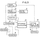
- Fig. 3 is a block diagram which illustrates functions performd in the CPU shown in Fig. 2.
- the X direction motor 2 is driven by the motor driver 15 with a pulse from a pulse generator 25 and at the same time, the number of the pulses is counted by a counter 26.
- the number of pulses as set by a pulse setting circuit 27 and the number of pulses as counted by the counter 26 are discriminated by a discriminating circuit 28 to conclude that the pulse as prescribed is outputted to the motor driver 15 by coincidence of the number of both pulses so that the pulse from the encoder 17 is inputted to the counter 18.
- a difference arithmetic circuit 29 serves to compare the calculated value of the counter 18 with that of the counter 26 to correct the number of pulses as set with set pulse numbers by means of a unit 30 for setting the correction.
- the number of pulses corresponding to the extent of movement as set by the pulse setting circuit 27 is outputted to the X direction motor 2 by the motor driver 15 to move the chip mounting head (Step 1). This will continue until the value calculated by the counter 26 amounts to the number of pulses as set by means of the discrimination circuit 28 (Step S2). If this will have the mounting head held stationary at a point A as shown in Fig. 5, there would be a difference ⁇ l since the mounting head should be originally at a point A o .
- L is the distance between the central axes of the pulleys
- l is the distance between the X direction motor 2 and the mounting head
- r is the radius each of the pulleys.
- the belt is tensioned to provide the difference ⁇ l so that the extent of elongation of the belt per unit length may be expressed by: ⁇ l/ (2L - l + ⁇ r)
- the distance L between the axes of the pulleys is 500mm to provide the slippage in the order of 50-100 ⁇ m to afford full detection power.
- Step S3 the number of pulses from the encoder 17d (Step S3) is inputted to the counter 18.
- Step S4 a differece between the number of output pulses and the number of input pulses from the encoder, that is, the aforementioned ⁇ is calculated by means of the arithmetic circuit 29 upon adopting a difference in the counted values between the counter 26 and 18.
- the value to be compensated which is stored in the memory 19 (ROM, RAM) is read from the difference in the pulses and the position l (Step S5) to set the number of pulses to be compensated to a pulse setting circuit 27 by a circuit 30 for setting the value to be compensated.
- the pulse setting circuit 27 serves to output the number of pulses to be compensated to the motor driver 15 (Step S6). Completion of the output of pulse to be compensated is determined by (Step S7).
- the value to be compensated is not applied to the memory 19 in (Step 5) but may be calculated in CPU 14 by use of the fromula (5) as often as the case may be.
- the compensation obtained from the formula (5) has been made by the drive pulley in this instance, this may also be made by use of the movable elements (fine adjustders such as the motor and piezoelectric element and the like) disposed on the mounting head 1.
- the location of the mounting head is not, however, incorporated in the formula (5). Instead, the compensation is made by only using the output pulse of the encoder on the side of the driven pulley to obtain the same effect or result. Otherwise, the value substantially approximate to the value obtained from the formula (5) may be mapped into the memory 19 to perform the same effect or result.
Landscapes
- Engineering & Computer Science (AREA)
- Manufacturing & Machinery (AREA)
- Microelectronics & Electronic Packaging (AREA)
- Operations Research (AREA)
- Control Of Position Or Direction (AREA)
- Supply And Installment Of Electrical Components (AREA)
Description
- This invention relates to a method and apparatus for positioning a mounting head of a chip component device, and more particularly to a control of a mounting head of a chip component mounting device, which is adapted so that the mounting head carried on a belt to be driven by a drive motor is controlled to pick up chip components for mounting the latter in a predetermined position on a substrate. Such an apparatus is disclosed in EP-A-0 248 904.
- A chip component mounting device has been heretofore fabricated so that the mounting head is normally supplied with a vacuum pressure and takes advantage thereof to suck the chip components fed from a chip supply station which is so called the "feeder". The mounting head is then moved by a motor in X-Y directions to mount the chip components in a predetermined position on the substrate. In this instance, the mounting head is disposed on a belt trained between a drive pulley connected to the motor and a driven pulley provided apart from the drive pulley at a certain distance and is moved thereby in the X-Y directions. Otherwise, two sets of ball screws and nuts are provided to move the mounting head in X-Y drives, thereby positioning the head.
- The belt which has been used in the aforementioned device is generally so called "timing belt" and is designed with a relatively high degree of accuracy. However, the head if moved to a great extent increases errors depending upon expansion or contraction of the belt. Consequently, for location of the mounting head, there is a difference in position between one case where the mounting head is advanced and another case where the mounting head is retracted. This difference may be in term of the value of ranging from 50 µm to 100 µm with head movement per about 500 mm. On the other hand, a chip component to be mounted by a chip component mounting device of this class is made in a micro size. Similarly, an integrated circuit element to be mounted by the mounting device is fabricated so that a pitch of a lead section is made very microscopic. For this reason, if the errors arise due to expansion or contraction of the timing belt as aforementioned, difficulties are involved in precisely mounting chip components.
- Although when the mounting head is driven by use of the balls and nuts. there is very few errors as compared with the belt drive, this renders a drive mechanism for the ball screws and nuts complicated to result in a high cost and requires so much careful attention to assembling as not to impose radial load to the screws. Further, the balls have a disadvantage in a noise generated due to friction sound when the mounting head is driven at a high speed.
- In view of what has discussed hereinbefore, the present invention is provided to eliminate the aforementioned disadvantages.
- It is a prime object of the invention to provide a method and apparatus for positioning a mounting head of a chip component mounting device, which is capable of precisely mounting the mounting head in a predetermined position whatever a belt may expand or contract when the mounting head is driven and controlled by the belt.
- The problem as above referred to is solved by a provision of a method for positioning a mounting head of a chip component mounting device wherein a head carried on a belt which is driven by a drive motor is controlled to pick up and mount a plurality of chip components in a predetermined position on a substrate, the method being composed of the steps of training the belt between a drive pulley connected to the drive motor and a driven pulley, measuring what difference in a rotational amount is between the drive pulley and the driven pulley, compensating slippage or deviation of the mounting head, which is derived from expansion or contraction of the belt according to the difference in the measured rotational amount between the pulley.
- The problem is also solved by a provision of an apparatus for positioning a mounting head of a chip component mounting device wherein a mounting head carried on a belt which is driven by a drive motor is controlled to pick up and mount a plurality of chip components in a predetermined position on a substrate, comprising a drive pulley connceted to a drive motor, a driven pulley disposed apart from said drive pulley and adapted for rotation by said belt, means for detecting the rotational amount of the drive pulley, and means for compensating slippage or deviation of the mounting head, which is derived from expansion or contraction of the belt according to the difference in the rotational amount between the pulleys.
- With this arrangement, the belt which carries the mounting head is trained between the two pulleys such as drive and driven pulleys and is driven thereby, viz. the former connected to the the drive motor and the latter disposed apart from the drive pulley at which time a difference in the rotational amount between the two pulleys is measured. The rotational amount of the drive pulley is the desired rotational amount when the mounting head is moved whereas the rotational amount of the driven pulley is indicative of the actual rotational amount in which the driven pulley is driven by the desired rotational amount. If the belt is made highly rigid, there is a little difference in the rotational amount. However, if the belt is expanded, the rotational amount the driven pulley do not correspond to the desired rotational amount but provides a big difference in the rotational amount. Accordingly, a difference in the rotational amount between the drive and the driven pulleys is indicative of slippage of the mounting head out of a predetermined position. In view thereof, according to the present invention, the difference in the rotational amount is measured to compensate slippage of the mounting head out of position, which is derived from expansion or contraction of the belt. This allows precise positioning of the mounting head even if the belt is expanded or contracted.
- The present invention will become apparent from the following detailed description of the invention when considered in conjunction with the accompanying drawings in which:
- Fig. 1 is a perspective view schematically showing an apparatus accoring to the present invention;
- Fig. 2 is a block diagram showing a belt drive mechanism adapted for driving a mounting head;
- Fig. 3 is a block diagram showing functions performd in a CPU (central processing unit);
- Fig. 4 is a flow chart showing a control sequence of the instant apparatus; and,
- Fig. 5 is a representation explanatory of slippage of the mounting head out of position, that is, a difference between the original position and the present position.
- Referring to Fig. 1, a chip component mounting device embodying the present invention is shown in general illustration. Numeral 1 designates a mounting head which normally takes advantage of vacuum pressure to suck chip components fed from a chip supply station (not shown). The mounting head 1 is carried in position on an
X-direction belt 6 which is trained between adrive pulley 4 and a driven pulley 7. Thedrive pulley 4 is driven from anX-direction motor 2 through abelt 5 trained between amotor pulley 3 and thedrive pulley 4. Thus, drive of themotor 2 allows thebelt 5 to rotate thedrive pulley 4 to move theX-direction belt 6, thereby moving the mounting head 1 in the drection of an arrow X. - A mechanism (such as the
X direction motor 2 or the like) for moving the mounting head in the direction of the arrow X is mounted in position on a Y-direction belt 11 which is trained between a drive pulley 10 and a drivenpulley 12. When the drive pulley 10 is rotated from a Y-direction motor 8 through a belt 9 to move the belt 11, that is, the mounting head 1 is moved in the diretion of the arrow Y. In this instance, X andY directon motors 2 and 8 are designed as a pulse motor or a servo motor. - The
X direction motor 2 is rotated at a predetermined rate by amotor driver 15 via a drive pulse outputted from aCPU 14 as shown in Fig. 2. Arotary encoder 17 is coupled by abelt 16 to the driven pulley 7. The output of therotary encoder 17 is applied by apulse counter 18 to theCPU 14. TheCPU 14 is connected to amemory 19 and to an external equipment by an I/O 20. - Fig. 3 is a block diagram which illustrates functions performd in the CPU shown in Fig. 2. The
X direction motor 2 is driven by themotor driver 15 with a pulse from apulse generator 25 and at the same time, the number of the pulses is counted by acounter 26. The number of pulses as set by apulse setting circuit 27 and the number of pulses as counted by thecounter 26 are discriminated by adiscriminating circuit 28 to conclude that the pulse as prescribed is outputted to themotor driver 15 by coincidence of the number of both pulses so that the pulse from theencoder 17 is inputted to thecounter 18. A differencearithmetic circuit 29 serves to compare the calculated value of thecounter 18 with that of thecounter 26 to correct the number of pulses as set with set pulse numbers by means of aunit 30 for setting the correction. - The operation of the instant apparatus arranged as aforesaid will be apprarent from the following description.
- As seen from the flow chart of Fig. 4, the number of pulses corresponding to the extent of movement as set by the
pulse setting circuit 27 is outputted to theX direction motor 2 by themotor driver 15 to move the chip mounting head (Step 1). This will continue until the value calculated by thecounter 26 amounts to the number of pulses as set by means of the discrimination circuit 28 (Step S2). If this will have the mounting head held stationary at a point A as shown in Fig. 5, there would be a difference Δℓ since the mounting head should be originally at a point Ao. This is a slippage of the mounting head out of the original position and renders theX-direction belt 6 tensioned (high tension) or slackened (low tension) as shown by the dot and dash line and the dotted line, respectively, of Fig. 5. - The length of the belt as high tensioned is expressed by:

where L is the distance between the central axes of the pulleys, ℓ is the distance between theX direction motor 2 and the mounting head, and r is the radius each of the pulleys. In other words, the belt is tensioned to provide the difference Δℓ so that the extent of elongation of the belt per unit length may be expressed by:
- This derives the extent of slippage of the
belt 6 at a point B (point of contact between the driven pulley 7 and the belt 6 ) may be formularized by:
- On the other hand, if an angular deviation of the driven pulley 7 (to be detected by the encoder 17), which is derived from slippage of the belt is put as Δϑ , a tangential deviation of the pulley is expressed by the following equation from the formula (3) when Δϑ·r is held.

- This derives the slippage of the
belt 6, which is formularized by:
- From the formula (5) where the distance L is between the central axes of the pulleys, and the radius r each of the pulleys is prescribed value, ℓ denoting the position where the head is driven, Δ is to be known. As Δϑ may be inputted from the encoder, the slippage Δℓ is obtained by perfoming calculations. Compensation for the deviation of the position may be made by dividing Δℓ by the raduis r of each of the pulleys and rotating the
motor 2. - In this case, if the units are found in terms of the values, where the distance L between the axises of the pulleys = 500mm, the diameter each of the pulley = 20mm, the resolution of encoder = 2,000 pulse/per rotation, and the reduction ratio of the driven pulley to the encoder = 1:4, the distance of the encoder 17 per one pulse on the side of the driven pulley 7 becomes 7.85µm. As previously set forth, the distance L between the axes of the pulleys is 500mm to provide the slippage in the order of 50-100 µm to afford full detection power. Supposing that the mounting head comes to a standstill at the central position ( ℓ =2/L=250mm) and a difference in pulses is 5 pulses from the encoder, the deviation of the position at the point A becomes 61 µm and is compensated by rotating the motor.
- Referring back to the flow chart of Fig. 4, the number of pulses from the encoder 17d (Step S3) is inputted to the
counter 18. Next, a differece between the number of output pulses and the number of input pulses from the encoder, that is, the aforementioned Δϑ is calculated by means of thearithmetic circuit 29 upon adopting a difference in the counted values between thecounter pulse setting circuit 27 by acircuit 30 for setting the value to be compensated. Thepulse setting circuit 27 serves to output the number of pulses to be compensated to the motor driver 15 (Step S6). Completion of the output of pulse to be compensated is determined by (Step S7). - It is noted that the value to be compensated is not applied to the
memory 19 in (Step 5) but may be calculated inCPU 14 by use of the fromula (5) as often as the case may be. - By application of the method according to the invention, it is ready to ascertain whether the belt is broken due to phenomena such as a difference in pulse trains of the encoder on the side of the driven pulley, expansion or contractraction derived from passage of time and ambient temperature, foreign matter interposed between the belt and the pulley, thereby ensuring that nothing is wrong.
- Although the compensation obtained from the formula (5) has been made by the drive pulley in this instance, this may also be made by use of the movable elements (fine adjustders such as the motor and piezoelectric element and the like) disposed on the mounting head 1.
- As is apparent from the formula (5), the closer the mounting head (load) is to the
drive pulley 4, the greater (maximun about twice) the value to be compensated is relative to the error in the output pulse of the encoder on the side of the driven pulley. In contrast, the closer the mounting head is to the driven pulley 7, the smaller the compensation is relative to the aforementioned error. The location of the mounting head is not, however, incorporated in the formula (5). Instead, the compensation is made by only using the output pulse of the encoder on the side of the driven pulley to obtain the same effect or result. Otherwise, the value substantially approximate to the value obtained from the formula (5) may be mapped into thememory 19 to perform the same effect or result.
Claims (4)
- An apparatus for positioning a mounting head of a chip component mounting device comprising:
a drive motor (2, 8),
a drive pulley (4, 10) connected to said drive motor,
a driven pulley (7, 12) driven by said drive pulley,
a belt (6, 11) between said drive pulley and said driven pulley, said belt mounting thereon the mounting head (1) for picking up a chip to mount the same on a substrate, wherein said mounting head may be out of position due to expansion or contraction of said belt,
first sensing means (25, 26) for sensing rotation amount of said drive pulley,
second sensing means (17) for sensing rotation amount of said driven pulley, and
means (19, 30, 15) responsive to difference between said rotation amount of said drive pulley and rotation amount of said driven pulley for compensating position of said mounting head. - An apparatus for positioning a mounting head of a chip component mounting device according to claim 1 wherein
said drive motor comprises a pulse motor (2, 8) and a pulse generator (25),
said first sensing means (25, 26) comprises a counter (26) for counting the number of pulse generated from said pulse generator, and
said second sensing means (17) comprises a rotary encoder (17) connected to said driven pulley and a counter (18) for counting the number of pulse generated from said rotary encoder. - An apparatus for positioning a mounting head of a chip component mounting device according to claim 1 wherein said compensating means (19, 30, 15) comprises:
means (29) for determining difference of said rotation amount of said drive pulley and rotation amount of said driven pulley,
means (19, 30) responsive to said difference of said rotation amount of said drive pulley and rotation amount of said driven pulley for determining correct position of said mounting head, and
means (15) responsive to said second determining means (19, 30) for driving said drive pulley to move said mounting head in correct position. - In a chip component mounting device having a belt (6, 11) between a drive pulley (4, 10) and a driven pulley (7, 12) and a mounting head (1) on said belt, wherein said mounting head may be out of position due to expansion or contraction of said belt, the method for positioning said mounting head comprising the steps of:
measuring the difference of the rotation amount of said drive pulley and the rotation amount of said driven pulley, and
moving said mounting head in response to said difference between said rotation amount of said drive pulley and said rotation amount of said driven pulley to correct the position of said mounting head.
Applications Claiming Priority (2)
| Application Number | Priority Date | Filing Date | Title |
|---|---|---|---|
| JP2110129A JPH0770875B2 (en) | 1990-04-27 | 1990-04-27 | Mounting head control method for chip component mounting apparatus and apparatus therefor |
| JP110129/90 | 1990-04-27 |
Publications (3)
| Publication Number | Publication Date |
|---|---|
| EP0454317A2 EP0454317A2 (en) | 1991-10-30 |
| EP0454317A3 EP0454317A3 (en) | 1992-09-02 |
| EP0454317B1 true EP0454317B1 (en) | 1994-11-09 |
Family
ID=14527763
Family Applications (1)
| Application Number | Title | Priority Date | Filing Date |
|---|---|---|---|
| EP91303134A Expired - Lifetime EP0454317B1 (en) | 1990-04-27 | 1991-04-09 | Method and apparatus for positioning a mounting head of chip component mounting device |
Country Status (3)
| Country | Link |
|---|---|
| EP (1) | EP0454317B1 (en) |
| JP (1) | JPH0770875B2 (en) |
| DE (1) | DE69105031T2 (en) |
Families Citing this family (3)
| Publication number | Priority date | Publication date | Assignee | Title |
|---|---|---|---|---|
| EP1076357A1 (en) * | 1999-08-11 | 2001-02-14 | SiMoTec GmbH | Mounting apparatus for processing microsystem products |
| JP4608772B2 (en) * | 2000-12-12 | 2011-01-12 | パナソニック株式会社 | Mounting machine |
| ITUB20155868A1 (en) * | 2015-11-05 | 2017-05-05 | Claudio Arrighi | OSCILLATING BRIDGE AXLE PUSHED BY FLAT BELT DRIVE FOR AUTOMATIC PRECISION POSITIONING MACHINE |
Family Cites Families (4)
| Publication number | Priority date | Publication date | Assignee | Title |
|---|---|---|---|---|
| US4304536A (en) * | 1980-10-07 | 1981-12-08 | International Business Machines Corporation | Green sheet support fixture speed and position control system for a screening machine |
| US4459743A (en) * | 1980-12-05 | 1984-07-17 | J. Osawa Camera Sales Co., Ltd. | Automatic mounting apparatus for chip components |
| JPS61148515A (en) * | 1984-12-24 | 1986-07-07 | Matsushita Electric Works Ltd | Packaging device of electronic parts |
| EP0248904A4 (en) * | 1985-11-27 | 1988-02-17 | Matsushita Electric Ind Co Ltd | Method of carrying out operation in working apparatus. |
-
1990
- 1990-04-27 JP JP2110129A patent/JPH0770875B2/en not_active Expired - Lifetime
-
1991
- 1991-04-09 EP EP91303134A patent/EP0454317B1/en not_active Expired - Lifetime
- 1991-04-09 DE DE69105031T patent/DE69105031T2/en not_active Expired - Fee Related
Also Published As
| Publication number | Publication date |
|---|---|
| DE69105031T2 (en) | 1995-06-22 |
| EP0454317A3 (en) | 1992-09-02 |
| DE69105031D1 (en) | 1994-12-15 |
| JPH0410600A (en) | 1992-01-14 |
| EP0454317A2 (en) | 1991-10-30 |
| JPH0770875B2 (en) | 1995-07-31 |
Similar Documents
| Publication | Publication Date | Title |
|---|---|---|
| US9144869B2 (en) | Machine motion trajectory measuring device, numerically controlled machine tool, and machine motion trajectory measuring method | |
| EP1666890A1 (en) | Rotary shaft control apparatus | |
| SE467665B (en) | PROCEDURE AND DEVICE FOR DETERMINING AND REGULATING THE TENSION IN A CIRCUIT | |
| EP0666520A1 (en) | Position detecting method and apparatus | |
| EP0331142B1 (en) | Numerical control device involving correction for lost motion | |
| US6750776B2 (en) | Machines having drive member and method for diagnosing the same | |
| EP0454317B1 (en) | Method and apparatus for positioning a mounting head of chip component mounting device | |
| US4296365A (en) | Method and apparatus for correcting errors of feeding of endless belt in automatic screen printing | |
| EP1223485B1 (en) | Positioning-controlling apparatus and positioning-controlling method, and part-mounting equipment and part-mounting method | |
| JP3444800B2 (en) | Tilt stage | |
| KR100268839B1 (en) | Position control device for a crane | |
| EP0476678A2 (en) | Method and apparatus for machining a non-circular workpiece | |
| JP2000186991A (en) | Method and device for measuring torsion spring constant | |
| WO2006082601A1 (en) | Machine for flexographic printing lines | |
| KR100233726B1 (en) | Transfer apparatus | |
| JPH08257849A (en) | Screw floating detecting device | |
| JP4166424B2 (en) | Semiconductor manufacturing equipment | |
| JPH11218941A (en) | Stage device and exposure device using the same | |
| KR100224862B1 (en) | Apparatus and method for callibration of robot arm | |
| JPH09160652A (en) | Moving distance correction method for belt driving mechanism and stepping motor driving device using the correction method | |
| EP0311077B1 (en) | Apparatus and method for feeding and positioning articles being processed | |
| US5297712A (en) | System for feeding and positioning articles being processed | |
| JP3279488B2 (en) | Calibration method and calibration device for physical quantity sensor | |
| KR20060034325A (en) | Image acquisition system and method thereof for the inferiority recognition of tunnel lining | |
| JP2941979B2 (en) | Method and apparatus for detecting thickness of plate material to be processed in bending apparatus |
Legal Events
| Date | Code | Title | Description |
|---|---|---|---|
| PUAI | Public reference made under article 153(3) epc to a published international application that has entered the european phase |
Free format text: ORIGINAL CODE: 0009012 |
|
| AK | Designated contracting states |
Kind code of ref document: A2 Designated state(s): CH DE FR LI NL |
|
| PUAL | Search report despatched |
Free format text: ORIGINAL CODE: 0009013 |
|
| AK | Designated contracting states |
Kind code of ref document: A3 Designated state(s): CH DE FR LI NL |
|
| 17P | Request for examination filed |
Effective date: 19930226 |
|
| 17Q | First examination report despatched |
Effective date: 19940114 |
|
| GRAA | (expected) grant |
Free format text: ORIGINAL CODE: 0009210 |
|
| AK | Designated contracting states |
Kind code of ref document: B1 Designated state(s): CH DE FR LI NL |
|
| REF | Corresponds to: |
Ref document number: 69105031 Country of ref document: DE Date of ref document: 19941215 |
|
| ET | Fr: translation filed | ||
| PGFP | Annual fee paid to national office [announced via postgrant information from national office to epo] |
Ref country code: DE Payment date: 19950410 Year of fee payment: 5 |
|
| PGFP | Annual fee paid to national office [announced via postgrant information from national office to epo] |
Ref country code: FR Payment date: 19950411 Year of fee payment: 5 |
|
| PGFP | Annual fee paid to national office [announced via postgrant information from national office to epo] |
Ref country code: CH Payment date: 19950413 Year of fee payment: 5 |
|
| PGFP | Annual fee paid to national office [announced via postgrant information from national office to epo] |
Ref country code: NL Payment date: 19950430 Year of fee payment: 5 |
|
| PLBE | No opposition filed within time limit |
Free format text: ORIGINAL CODE: 0009261 |
|
| STAA | Information on the status of an ep patent application or granted ep patent |
Free format text: STATUS: NO OPPOSITION FILED WITHIN TIME LIMIT |
|
| 26N | No opposition filed | ||
| PG25 | Lapsed in a contracting state [announced via postgrant information from national office to epo] |
Ref country code: LI Effective date: 19960430 Ref country code: CH Effective date: 19960430 |
|
| PG25 | Lapsed in a contracting state [announced via postgrant information from national office to epo] |
Ref country code: NL Effective date: 19961101 |
|
| REG | Reference to a national code |
Ref country code: CH Ref legal event code: PL |
|
| PG25 | Lapsed in a contracting state [announced via postgrant information from national office to epo] |
Ref country code: FR Effective date: 19961227 |
|
| PG25 | Lapsed in a contracting state [announced via postgrant information from national office to epo] |
Ref country code: DE Effective date: 19970101 |
|
| NLV4 | Nl: lapsed or anulled due to non-payment of the annual fee |
Effective date: 19961101 |
|
| REG | Reference to a national code |
Ref country code: FR Ref legal event code: ST |