EP0453412A1 - A feeding device for animal foodstuffs permitting adjustment of the feed level - Google Patents
A feeding device for animal foodstuffs permitting adjustment of the feed level Download PDFInfo
- Publication number
- EP0453412A1 EP0453412A1 EP91830118A EP91830118A EP0453412A1 EP 0453412 A1 EP0453412 A1 EP 0453412A1 EP 91830118 A EP91830118 A EP 91830118A EP 91830118 A EP91830118 A EP 91830118A EP 0453412 A1 EP0453412 A1 EP 0453412A1
- Authority
- EP
- European Patent Office
- Prior art keywords
- distributor
- plate
- feed
- feeding device
- annulus
- Prior art date
- Legal status (The legal status is an assumption and is not a legal conclusion. Google has not performed a legal analysis and makes no representation as to the accuracy of the status listed.)
- Granted
Links
Images


Classifications
-
- A—HUMAN NECESSITIES
- A01—AGRICULTURE; FORESTRY; ANIMAL HUSBANDRY; HUNTING; TRAPPING; FISHING
- A01K—ANIMAL HUSBANDRY; AVICULTURE; APICULTURE; PISCICULTURE; FISHING; REARING OR BREEDING ANIMALS, NOT OTHERWISE PROVIDED FOR; NEW BREEDS OF ANIMALS
- A01K39/00—Feeding or drinking appliances for poultry or other birds
- A01K39/01—Feeding devices
- A01K39/012—Feeding devices filling automatically, e.g. by gravity from a reserve
- A01K39/0125—Panfeeding systems; Feeding pans therefor
Definitions
- the present invention relates to a feeding device for animal foodstuffs permitting adjustment of the feed level in feed-distribution lines for chicken farming in sheds.
- the feeding devices in question substantially consist of a containing plate provided on the periphery thereof with a metal grating or cage fastened to an annulus disposed in coaxial relation externally to a cylindrical upright distributor located above the containing plate and inside which feed coming from a horizontal tubular duct supported by ropes flows.
- the distributor is connected to the horizontal tubular duct at the upper part thereof and is suspended therefrom.
- the feed level in the containing plate (high level in case of chicks, low level in case of chickens) is determined by the relative vertical distance between the cylindrical distributor and the containing plate located under it. Practically the distributor is slidably moved by hand relative to the annulus external to it between two positions of maximum and minimum distance from the containing plate respectively, thereby giving rise to a variation of the feed level in the containing plate.
- the position adjustment of the cylindrical distributor is carried out by an operator who acts on each feeding device individually. He moves the cylindrical distributor downwardly as the animal size grows thereby decreasing the feed level in the plate and subsequently (when the chickens have reached a bigger size) raises the containing plate from ground. Therefore nowadays the operator intervenes on each feeding device individually in order to carry out said adjustments.
- the position adjustment of the distributor relative to the containing plate is carried out by the use of metal supporting hooks provided on the plate and engaged in holes arranged on the distributor outer surface at different heights.
- a further object of the invention is to provide a feeding device allowing a reduced waste of feed by the animals.
- 1 denotes a containing plate provided on its periphery with a metal grating or cage 2 that is fastened, at the upper part thereof, to an annulus 3.
- Annulus 3 is disposed in coaxial relation to the outside of a hollow cylindrical upright distributor 4, which is capable of vertically sliding within the annulus 3 between two positions of maximum and minimum distance from the plate 1, respectively.
- the distributor 4 is connected at the upper part thereof to a feed-carrying horinzontal tubular duct 5 which is supported by ropes 6 mounted on a manually operated winch (not shown).
- reference numeral 7 denotes feed, the level of which is determined by the distance of the bottom outlet of the distributor 4 from plate 1.
- feed carreid within the duct 5 by a screw feeder enters the distributor 4 and is discharged into the plate 1.
- the highest position of the distributor 4 corresponds to the maximum feed level in plate 1.
- This situation shown in Fig. 4a, is adapted for chick feeding.
- a pair of vertical rectilinear recesses 8 located at diametrically opposite positions. Housed in each of them is a flat spring 9 fastened to the lower base of the recess 8 and having the upper free end substantially folded according to a C-shaped configuration so as to form a housing 10 within which one of the teeth 11 disposed on the inner part of annulus 3 can be snap-fitted when the distributor 4, due to the lowering of the duct 5, reaches its position of minimum distance from plate 1. This situation is shown in Figs. 3 and 4c.
- each tooth 11 slides on the spring 9 when the distributor 4 is moved downwardly towards the plate 1, as far as it is fitted in the housing 10.
- the C-shaped configuration of housing 10, as viewed from Figs. 2 and 3, comprises a folded back piece 12 at the upper part thereof, which enables the distributor 4 to be disengaged from the annulus 3 by exerting a manual pressure in a centripetal direction relative to the distributor itself. It is to be noted however that this intervention is necessary only at the end of the animals' feeding period, when the starting positions are to be restored (chicks' feeding).
- a ring 13 which is raised relative to the plate 1 bottom, is placed within the containing plate 1, in the area included between the peripheral edge of the plate 1 and its central part overlain by the distributor 4.
- This ring 13 has the function of facilitating the exit of the chicks that, passing through the metal cage 2, may have entered the plate 1. Actually this facilitation in coming out of the plate 1 helps in reducing the feed waste.
- the ring 13 acts as a rest the chicks' claws. In addition it helps preventing the bigger animals from moving feed 7 too much towards the plate rim. In fact chickens tend to eat the fresher feed under the distributor 4 moving the other feed away towards the plate 1 thereby causing its coming out.
- Blades 14 As shown in Fig. 1. fastened to the ring 13 are some blades 14 disposed radially in vertical planes joining the ring 13 to a collar 15 disposed in coaxial relation on the outside of the distributor 4. Blades 14 create an obstacle to the entry and stay of the animals in plate 1. In addition they allow the number of days during which chicks can enter the plate 1 to be restrained. Actually, in the absence of blades 14 animals could go on entering the plate 1 until they are fifteen days old. Due to the presence of blades 14, animals have been found to stop entering the plate 1 when they are about seven days old, which is a clear advantage from the point of view of the reduction of feed waste.
- the invention attains the intended purposes.
Landscapes
- Life Sciences & Earth Sciences (AREA)
- Environmental Sciences (AREA)
- Birds (AREA)
- Animal Husbandry (AREA)
- Biodiversity & Conservation Biology (AREA)
- Feeding And Watering For Cattle Raising And Animal Husbandry (AREA)
- Stereo-Broadcasting Methods (AREA)
- Blow-Moulding Or Thermoforming Of Plastics Or The Like (AREA)
Abstract
Description
- The present invention relates to a feeding device for animal foodstuffs permitting adjustment of the feed level in feed-distribution lines for chicken farming in sheds.
- It is known that the feeding devices in question substantially consist of a containing plate provided on the periphery thereof with a metal grating or cage fastened to an annulus disposed in coaxial relation externally to a cylindrical upright distributor located above the containing plate and inside which feed coming from a horizontal tubular duct supported by ropes flows. The distributor is connected to the horizontal tubular duct at the upper part thereof and is suspended therefrom.
- It is known that the feed level in the containing plate (high level in case of chicks, low level in case of chickens) is determined by the relative vertical distance between the cylindrical distributor and the containing plate located under it. Practically the distributor is slidably moved by hand relative to the annulus external to it between two positions of maximum and minimum distance from the containing plate respectively, thereby giving rise to a variation of the feed level in the containing plate.
- Presently, in accordance with the known art, the position adjustment of the cylindrical distributor is carried out by an operator who acts on each feeding device individually. He moves the cylindrical distributor downwardly as the animal size grows thereby decreasing the feed level in the plate and subsequently (when the chickens have reached a bigger size) raises the containing plate from ground. Therefore nowadays the operator intervenes on each feeding device individually in order to carry out said adjustments.
- The operator's intervening represents a clear drawback due to the great waste of time, taking into account the fact that there is a great number of feeding devices in the various feed distribution lines in the sheds.
- It is also to be noted that the operator, in order to avoid wasting time, tends to intervene on the feeding devices the lowest number of times. Practically there is therefore a passage from a completely raised position of the distributor to a completely lowered position without any intermediate adjustment. As is known, this brings about an important waste of feed by the animals, since the feed level is not accurately adjusted depending on the size reached by the animals.
- Presently, still in accordance with the known art, the position adjustment of the distributor relative to the containing plate is carried out by the use of metal supporting hooks provided on the plate and engaged in holes arranged on the distributor outer surface at different heights.
- In a second adjustment system provision is made for the use of notches disposed on the distributor and engaged by a pair of teeth resting thereon, which are provided on the annulus supporting the containing plate.
- In both cases however the intervening of an operator is always foreseen and he is obliged to act on each feeding device individually, which involves the above mentioned drawbacks.
- Consequently it is an important object of the present invention to provide a feeding device permitting level adjustment to the animals size without needing direct and individual manual interventions on the feeding device itself.
- A further object of the invention is to provide a feeding device allowing a reduced waste of feed by the animals.
- The foregong and further objects are all attained by the feeding device in accordance with the invention the main features of which are set forth in the appended claims.
- Further features and advantages of the present invention will best be understood from the following detailed description of a preferred embodiment of a feeding device given hereinafter by way of non-limiting example with reference to the accompanying drawings, in which:
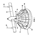
- Fig. 1 is a perspective view of the feeding device of the invention;
- Fig. 2 is a cross-sectional vertical view of the cylindrical distributor in its highest position (maximum distance from the containing plate);
- Fig. 3 is a vertical cross-sectional view of the cylindrical distributor in its lowest podition (minimum distance from the containing plate);
- Fig. 4a to 4e show the different adjustments of the feeding device according to the various animals sizes.
- Referring to the drawings, 1 denotes a containing plate provided on its periphery with a metal grating or
cage 2 that is fastened, at the upper part thereof, to anannulus 3.Annulus 3 is disposed in coaxial relation to the outside of a hollow cylindricalupright distributor 4, which is capable of vertically sliding within theannulus 3 between two positions of maximum and minimum distance from the plate 1, respectively. - The
distributor 4 is connected at the upper part thereof to a feed-carrying horinzontaltubular duct 5 which is supported byropes 6 mounted on a manually operated winch (not shown). - Referring to Figs. 4a to 4e,
reference numeral 7 denotes feed, the level of which is determined by the distance of the bottom outlet of thedistributor 4 from plate 1. In fact, feed carreid within theduct 5 by a screw feeder (not shown) enters thedistributor 4 and is discharged into the plate 1. - Since the
distributor 4 is supported by theduct 5, in order to move thedistributor 4 closer to the plate 1 it is sufficient to act on the winch and cause the lowering of theduct 5 by the desired amount. In this manner by a single operation is it possible to carry out the desired adjustment of the distributor height relative to the plate 1, in all feeding devices of the same feed distribution line. - As already said, the highest position of the
distributor 4 corresponds to the maximum feed level in plate 1. This situation, shown in Fig. 4a, is adapted for chick feeding. - After some days during which animals have grown is size, the situation will be that shown in Fig. 4a to which an intermediate position of the
distributor 4 will correspond. The animals size will go on growing and the situation will then be that shown in Fig. 4c, corresponding to the maximum approaching of thedistributor 4 to the plate 1, that is the maximum lowering ofduct 5 and consequently the minimum level of feed in plate 1. - In the three cases shown in Fig. 4a, 4b and 4c the containing plate 1 always rests on ground.
- Provided on the outer surface of the
distributor 4 is a pair of verticalrectilinear recesses 8 located at diametrically opposite positions. Housed in each of them is aflat spring 9 fastened to the lower base of therecess 8 and having the upper free end substantially folded according to a C-shaped configuration so as to form ahousing 10 within which one of theteeth 11 disposed on the inner part ofannulus 3 can be snap-fitted when thedistributor 4, due to the lowering of theduct 5, reaches its position of minimum distance from plate 1. This situation is shown in Figs. 3 and 4c. - It is to be noted that each
tooth 11 slides on thespring 9 when thedistributor 4 is moved downwardly towards the plate 1, as far as it is fitted in thehousing 10. - The C-shaped configuration of
housing 10, as viewed from Figs. 2 and 3, comprises a foldedback piece 12 at the upper part thereof, which enables thedistributor 4 to be disengaged from theannulus 3 by exerting a manual pressure in a centripetal direction relative to the distributor itself. It is to be noted however that this intervention is necessary only at the end of the animals' feeding period, when the starting positions are to be restored (chicks' feeding). - After some days, by virtue of the stable coupling between the
distributor 4 and annulus 3 (which is integral to the plate 1), it is possible by a single intervention on the winch to raise theduct 5 so as to cause the lifting of the plate 1 to the desired height. This situation is shown in Fig. 4d. - After some more days, when chicken have reached the maximum expected size before they are sent to slaughtering, by intervening on the winch the
duct 5 will be raised still more and the whole feeding device line together with it. This situation is shown in Fig. 4e. - It will be recognized that all the steps shown in Figs. 4a to 4e take place without any direct intervention on the individual feeding devices.
- In order to reduce the waste of feed by the animals to the minimum, the following expedients have been adopted.
- A
ring 13 which is raised relative to the plate 1 bottom, is placed within the containing plate 1, in the area included between the peripheral edge of the plate 1 and its central part overlain by thedistributor 4. Thisring 13 has the function of facilitating the exit of the chicks that, passing through themetal cage 2, may have entered the plate 1. Actually this facilitation in coming out of the plate 1 helps in reducing the feed waste. - Practically the
ring 13 acts as a rest the chicks' claws. In addition it helps preventing the bigger animals from movingfeed 7 too much towards the plate rim. In fact chickens tend to eat the fresher feed under thedistributor 4 moving the other feed away towards the plate 1 thereby causing its coming out. - The presence of the
ring 13 enables these drawbacks to be overcome. - As shown in Fig. 1. fastened to the
ring 13 are someblades 14 disposed radially in vertical planes joining thering 13 to acollar 15 disposed in coaxial relation on the outside of thedistributor 4.Blades 14 create an obstacle to the entry and stay of the animals in plate 1. In addition they allow the number of days during which chicks can enter the plate 1 to be restrained. Actually, in the absence ofblades 14 animals could go on entering the plate 1 until they are fifteen days old. Due to the presence ofblades 14, animals have been found to stop entering the plate 1 when they are about seven days old, which is a clear advantage from the point of view of the reduction of feed waste. - The invention attains the intended purposes.
- Obviously in its practical accomplishment modifications and variations may be made to the invention as above described without departing from the scope of the invention itself. In addition, all of the details can be replaced by technically aquivalent elements and the shapes and sizes as well as the materials used may be of any nature and magnitude depending upon requirements.
Claims (3)
- A feeding device for animal foodstuffs permitting adjustment of the feed level, of the type comprising a containing plate (1) provided on the periphery thereof with a metal grating or cage (2) fastened to an annulus (3) disposed in coaxial relation externally to a cylindrical upright distributor (4) vertically sliding within the annulus (3), between two positions of maximum and minimum distance from the plate (1) respectively, connected at the upper part thereof to a feed-carrying horizontal tubular duct (5) supported by ropes (6), said distributor (4) causing the discharge of feed (7) into the containing plate 1, the feed level in the plate (1) depending on the distance of the distributor (4) from the plate (1), characterized in that said distributor (4) is moved close to the containing plate (1) by lowering the horizontal tubular duct (5) and has a number of rectilinear recesses (8) disposed vertically on its outer surface, within each of said recesses being accommodated a flat spring (9) fastened to the lower base of the recess (8) and having the upper free end thereof substantially folded according to a C-shaped configuration so as to form a housing (10) within which one of the teeth (11) located on the inner part of the annulus (3) can be snap-fitted, when said distributor (4) reaches said position of minimum distance from the containing plate (1) by effect of the lowering of the horinzontal tubular duct (5).
- A feeding device for animal foodstuffs permitting adjustment of the feed level according to claim 1, characterized in that located within said containing plate (1), in the area included between the peripheral edge thereof and its central part overlain by said distributor (4), is a ring (13) which is spaced apart from the plate bottom.
- A feeding device for animal foodstuffs permitting adjustment of the feed level according to claim 2, characterized in that blades (14) are associated with said ring (13) and they are disposed radially in vertical planes joining said ring (13) to a collar (15) coaxially disposed on the outside of said distributor (4).
Priority Applications (1)
| Application Number | Priority Date | Filing Date | Title |
|---|---|---|---|
| AT91830118T ATE89977T1 (en) | 1990-04-11 | 1991-03-26 | FEEDERS FOR ANIMALS, WHICH CONTROL THE FEED LEVEL IS POSSIBLE. |
Applications Claiming Priority (2)
| Application Number | Priority Date | Filing Date | Title |
|---|---|---|---|
| IT84940A IT1239319B (en) | 1990-04-11 | 1990-04-11 | FEEDER WITH FEED LEVEL ADJUSTMENT. |
| IT8494090 | 1990-04-11 |
Publications (2)
| Publication Number | Publication Date |
|---|---|
| EP0453412A1 true EP0453412A1 (en) | 1991-10-23 |
| EP0453412B1 EP0453412B1 (en) | 1993-06-02 |
Family
ID=11326145
Family Applications (1)
| Application Number | Title | Priority Date | Filing Date |
|---|---|---|---|
| EP91830118A Expired - Lifetime EP0453412B1 (en) | 1990-04-11 | 1991-03-26 | A feeding device for animal foodstuffs permitting adjustment of the feed level |
Country Status (6)
| Country | Link |
|---|---|
| US (1) | US5101765A (en) |
| EP (1) | EP0453412B1 (en) |
| AT (1) | ATE89977T1 (en) |
| DE (1) | DE69100099T2 (en) |
| ES (1) | ES2041203T3 (en) |
| IT (1) | IT1239319B (en) |
Cited By (4)
| Publication number | Priority date | Publication date | Assignee | Title |
|---|---|---|---|---|
| US5733837A (en) * | 1993-05-10 | 1998-03-31 | Sakai Chemical Industry Co., Ltd. | Catalyst for catalytic reduction of nitrogen oxides |
| CN106359169A (en) * | 2016-09-23 | 2017-02-01 | 重庆牧宇农业发展有限公司 | Intelligent feed dropping device for chicken farm |
| CN109529657A (en) * | 2018-10-26 | 2019-03-29 | 刘小莉 | A kind of feeder of the poultry house convenient for adjusting feeding amount |
| CN110999820A (en) * | 2020-01-23 | 2020-04-14 | 厦门大学嘉庚学院 | Automatic quantitative feeding device for wild birds |
Families Citing this family (25)
| Publication number | Priority date | Publication date | Assignee | Title |
|---|---|---|---|---|
| US5406907A (en) * | 1993-11-24 | 1995-04-18 | Big Dutchman Inc. | Controlled pan feeder system for poultry |
| US5778821A (en) * | 1995-01-23 | 1998-07-14 | F&M Horwood Nominees Pty. Ltd. | Restricted flow poultry feeder |
| NL1003490C2 (en) * | 1996-07-03 | 1998-01-07 | Roxell Nv | Feeding device for poultry. |
| US5794562A (en) * | 1997-01-21 | 1998-08-18 | Big Dutchman, Inc. | Poultry breeder pan feeding system and pan feeder assembly therefor |
| US5875733A (en) * | 1997-07-25 | 1999-03-02 | Chen; Ai-Mei | Feeding device for poultry |
| ES2172428B1 (en) * | 2000-10-03 | 2005-03-16 | Gener Romeu Guardia | DINING ROOM FOR CORRAL BIRDS |
| NL1016638C2 (en) * | 2000-11-17 | 2002-05-22 | Roxell Nv | Feed distribution system for poultry. |
| DE10164100C1 (en) * | 2001-12-24 | 2003-04-03 | Big Dutchman Int Gmbh | Device for feeding poultry, especially fattening poultry, preferably broilers, freely roaming around a stall comprises feed conveying tube having branched openings assigned to a shell device which has a downpipe of inner/outer cylinders |
| DE10164122C1 (en) * | 2001-12-24 | 2003-05-15 | Big Dutchman Int Gmbh | System for automatic feeding of battery poultry has feeders suspended under height adjustable distribution ducts whose height setting opens different feeding ports |
| US7587990B2 (en) * | 2005-10-11 | 2009-09-15 | Ctb, Inc. | Pan breeder feeder |
| US7581512B2 (en) | 2005-10-11 | 2009-09-01 | Ctb, Inc. | Pan breeder feeder |
| US7584716B2 (en) | 2005-10-11 | 2009-09-08 | Ctb, Inc. | Pan breeder feeder |
| IL178323A0 (en) * | 2006-09-26 | 2007-02-11 | Plasson Ltd | Method of feeding poultry and poultry feeders particularly useful in such method |
| USD564712S1 (en) | 2006-10-10 | 2008-03-18 | Ctb Ip, Inc. | Pan of a feeder assembly |
| USD583112S1 (en) | 2006-10-10 | 2008-12-16 | Ctb, Inc. | Grill of a feeder assembly |
| NL2001700C2 (en) * | 2008-06-19 | 2009-12-22 | Roxell Nv | Feeding device for poultry having non-sharp-edged circumferentially closed bars or other parts delimiting feed opening between the bars. |
| USD625886S1 (en) * | 2009-01-08 | 2010-10-19 | The Gsi Group, Llc | Animal feeder |
| US9382070B2 (en) | 2012-10-24 | 2016-07-05 | Big Dutchman International Gmbh | Conveyor and method to convey animal products in an agricultural business |
| USD701654S1 (en) * | 2013-06-18 | 2014-03-25 | Francisco Javier Septien Prieto | Bird feeder |
| USD701354S1 (en) * | 2013-06-20 | 2014-03-18 | Francisco Javier Septien Prieto | Bird feeder |
| DE202014007282U1 (en) | 2014-09-12 | 2015-12-16 | Big Dutchman International Gmbh | metering |
| DE202016105370U1 (en) | 2016-09-27 | 2018-01-02 | Big Dutchman International Gmbh | Feeding device for poultry |
| IT201800006493A1 (en) * | 2018-06-20 | 2019-12-20 | FEEDER FOR ANIMAL BREEDING WITH IMPROVED REGULATION OF THE FEED LEVEL | |
| USD950860S1 (en) | 2020-10-01 | 2022-05-03 | Michael Landon De Smet | Poultry feeding/watering station |
| DE102022106585B4 (en) * | 2022-03-21 | 2023-10-19 | F I B R O Gmbh | Slide arrangement |
Citations (1)
| Publication number | Priority date | Publication date | Assignee | Title |
|---|---|---|---|---|
| US4722301A (en) * | 1986-05-08 | 1988-02-02 | Strong George W | Brooder feeding apparatus |
Family Cites Families (7)
| Publication number | Priority date | Publication date | Assignee | Title |
|---|---|---|---|---|
| US984980A (en) * | 1909-10-25 | 1911-02-21 | Arthur Bernard Taylor | Animal feed-trough. |
| US2505396A (en) * | 1946-09-23 | 1950-04-25 | Ray A Grindstaff | Rabbit feeder |
| US3388690A (en) * | 1965-10-22 | 1968-06-18 | Chore Time Equipment | Poultry feeder system and pan assembly therefor |
| US3811412A (en) * | 1970-09-22 | 1974-05-21 | Chore Time Equipment | Poultry feeder |
| SU745450A1 (en) * | 1977-08-16 | 1980-07-07 | За витель А. Н. Щегопев | Fodder spreader |
| IT8064275U1 (en) * | 1980-07-29 | 1982-01-29 | Ska Spa | FEEDING TROUGH WITH FEED LEVEL ADJUSTMENT, FOR LOWER OUTLET |
| IT1175175B (en) * | 1983-07-13 | 1987-07-01 | Ska Spa | FEEDER WITH FEED LEVEL ADJUSTMENT FOR BREEDING BIRDS, IN PARTICULAR FOR TURKEYS |
-
1990
- 1990-04-11 IT IT84940A patent/IT1239319B/en active IP Right Grant
-
1991
- 1991-03-26 ES ES199191830118T patent/ES2041203T3/en not_active Expired - Lifetime
- 1991-03-26 EP EP91830118A patent/EP0453412B1/en not_active Expired - Lifetime
- 1991-03-26 AT AT91830118T patent/ATE89977T1/en active
- 1991-03-26 DE DE91830118T patent/DE69100099T2/en not_active Expired - Fee Related
- 1991-04-11 US US07/683,634 patent/US5101765A/en not_active Expired - Fee Related
Patent Citations (1)
| Publication number | Priority date | Publication date | Assignee | Title |
|---|---|---|---|---|
| US4722301A (en) * | 1986-05-08 | 1988-02-02 | Strong George W | Brooder feeding apparatus |
Non-Patent Citations (1)
| Title |
|---|
| CHORE TIME N.V. 'MINIMAX: FUTTERSYSTEM FÜR MASTHÄNCHEN' November 1, 1988 , CHORE TIME N.V. , MALDEGEM (BE) DER MINIMAX WÄCHST MIT IHREN TIERENÜ * |
Cited By (4)
| Publication number | Priority date | Publication date | Assignee | Title |
|---|---|---|---|---|
| US5733837A (en) * | 1993-05-10 | 1998-03-31 | Sakai Chemical Industry Co., Ltd. | Catalyst for catalytic reduction of nitrogen oxides |
| CN106359169A (en) * | 2016-09-23 | 2017-02-01 | 重庆牧宇农业发展有限公司 | Intelligent feed dropping device for chicken farm |
| CN109529657A (en) * | 2018-10-26 | 2019-03-29 | 刘小莉 | A kind of feeder of the poultry house convenient for adjusting feeding amount |
| CN110999820A (en) * | 2020-01-23 | 2020-04-14 | 厦门大学嘉庚学院 | Automatic quantitative feeding device for wild birds |
Also Published As
| Publication number | Publication date |
|---|---|
| DE69100099T2 (en) | 1993-10-07 |
| ATE89977T1 (en) | 1993-06-15 |
| ES2041203T3 (en) | 1993-11-01 |
| EP0453412B1 (en) | 1993-06-02 |
| DE69100099D1 (en) | 1993-07-08 |
| IT9084940A0 (en) | 1990-04-11 |
| IT1239319B (en) | 1993-10-19 |
| IT9084940A1 (en) | 1991-10-11 |
| US5101765A (en) | 1992-04-07 |
Similar Documents
| Publication | Publication Date | Title |
|---|---|---|
| EP0453412B1 (en) | A feeding device for animal foodstuffs permitting adjustment of the feed level | |
| US3388690A (en) | Poultry feeder system and pan assembly therefor | |
| US3811412A (en) | Poultry feeder | |
| EP1095560B1 (en) | Feeding pan for poultry | |
| US6050220A (en) | Poultry feeder with adjustable feed level control | |
| EP0105571B1 (en) | Adjustable feeder with brood gate | |
| US11980166B2 (en) | Poultry feeder including pan means and removably attached drop tube | |
| US5092274A (en) | Poultry feeder | |
| US4527513A (en) | Poultry waterer | |
| US4995343A (en) | Feeder apparatus | |
| EP0665711B1 (en) | Poultry feeding device | |
| DE673196T1 (en) | POULTRY FEEDER. | |
| KR950703848A (en) | Poultry breeding and breeding methods | |
| EP0378039A1 (en) | Fowl feeder | |
| US5642688A (en) | Apparatus for feeding animals such as fowl | |
| EP0421553A1 (en) | Adjustable feeding device for poultry | |
| KR19990044944A (en) | Adjustable poultry feed bin assembly | |
| WO1994013130B1 (en) | Poultry feeder | |
| US4007711A (en) | Anti-pest pet dish | |
| KR19990067998A (en) | Adjustable poultry feeder assembly | |
| DE69208138D1 (en) | Automatic feeder for young poultry, especially for turkeys | |
| EP3222140A1 (en) | Feeding trough for poultry farming | |
| KR101760569B1 (en) | Feed of supply equipment | |
| US907227A (en) | Feeding apparatus. | |
| IT201800006493A1 (en) | FEEDER FOR ANIMAL BREEDING WITH IMPROVED REGULATION OF THE FEED LEVEL |
Legal Events
| Date | Code | Title | Description |
|---|---|---|---|
| PUAI | Public reference made under article 153(3) epc to a published international application that has entered the european phase |
Free format text: ORIGINAL CODE: 0009012 |
|
| AK | Designated contracting states |
Kind code of ref document: A1 Designated state(s): AT BE CH DE DK ES FR GB GR LI LU NL SE |
|
| 17P | Request for examination filed |
Effective date: 19920327 |
|
| 17Q | First examination report despatched |
Effective date: 19920722 |
|
| GRAA | (expected) grant |
Free format text: ORIGINAL CODE: 0009210 |
|
| AK | Designated contracting states |
Kind code of ref document: B1 Designated state(s): AT BE CH DE DK ES FR GB GR LI LU NL SE |
|
| PG25 | Lapsed in a contracting state [announced via postgrant information from national office to epo] |
Ref country code: SE Effective date: 19930602 Ref country code: LI Effective date: 19930602 Ref country code: GR Free format text: LAPSE BECAUSE OF FAILURE TO SUBMIT A TRANSLATION OF THE DESCRIPTION OR TO PAY THE FEE WITHIN THE PRESCRIBED TIME-LIMIT Effective date: 19930602 Ref country code: DK Effective date: 19930602 Ref country code: CH Effective date: 19930602 Ref country code: AT Effective date: 19930602 |
|
| REF | Corresponds to: |
Ref document number: 89977 Country of ref document: AT Date of ref document: 19930615 Kind code of ref document: T |
|
| REF | Corresponds to: |
Ref document number: 69100099 Country of ref document: DE Date of ref document: 19930708 |
|
| ET | Fr: translation filed | ||
| REG | Reference to a national code |
Ref country code: CH Ref legal event code: PL |
|
| REG | Reference to a national code |
Ref country code: ES Ref legal event code: FG2A Ref document number: 2041203 Country of ref document: ES Kind code of ref document: T3 |
|
| PG25 | Lapsed in a contracting state [announced via postgrant information from national office to epo] |
Ref country code: LU Free format text: LAPSE BECAUSE OF NON-PAYMENT OF DUE FEES Effective date: 19940331 |
|
| PLBE | No opposition filed within time limit |
Free format text: ORIGINAL CODE: 0009261 |
|
| STAA | Information on the status of an ep patent application or granted ep patent |
Free format text: STATUS: NO OPPOSITION FILED WITHIN TIME LIMIT |
|
| 26N | No opposition filed | ||
| REG | Reference to a national code |
Ref country code: GB Ref legal event code: IF02 |
|
| PGFP | Annual fee paid to national office [announced via postgrant information from national office to epo] |
Ref country code: FR Payment date: 20020312 Year of fee payment: 12 |
|
| PGFP | Annual fee paid to national office [announced via postgrant information from national office to epo] |
Ref country code: ES Payment date: 20020321 Year of fee payment: 12 |
|
| PGFP | Annual fee paid to national office [announced via postgrant information from national office to epo] |
Ref country code: GB Payment date: 20020327 Year of fee payment: 12 |
|
| PGFP | Annual fee paid to national office [announced via postgrant information from national office to epo] |
Ref country code: NL Payment date: 20020328 Year of fee payment: 12 |
|
| PGFP | Annual fee paid to national office [announced via postgrant information from national office to epo] |
Ref country code: DE Payment date: 20020404 Year of fee payment: 12 |
|
| PGFP | Annual fee paid to national office [announced via postgrant information from national office to epo] |
Ref country code: BE Payment date: 20020527 Year of fee payment: 12 |
|
| PG25 | Lapsed in a contracting state [announced via postgrant information from national office to epo] |
Ref country code: GB Free format text: LAPSE BECAUSE OF NON-PAYMENT OF DUE FEES Effective date: 20030326 |
|
| PG25 | Lapsed in a contracting state [announced via postgrant information from national office to epo] |
Ref country code: ES Free format text: LAPSE BECAUSE OF NON-PAYMENT OF DUE FEES Effective date: 20030327 |
|
| PG25 | Lapsed in a contracting state [announced via postgrant information from national office to epo] |
Ref country code: BE Free format text: LAPSE BECAUSE OF NON-PAYMENT OF DUE FEES Effective date: 20030331 |
|
| BERE | Be: lapsed |
Owner name: *SKA S.P.A. Effective date: 20030331 |
|
| PG25 | Lapsed in a contracting state [announced via postgrant information from national office to epo] |
Ref country code: NL Free format text: LAPSE BECAUSE OF NON-PAYMENT OF DUE FEES Effective date: 20031001 Ref country code: DE Free format text: LAPSE BECAUSE OF NON-PAYMENT OF DUE FEES Effective date: 20031001 |
|
| GBPC | Gb: european patent ceased through non-payment of renewal fee |
Effective date: 20030326 |
|
| PG25 | Lapsed in a contracting state [announced via postgrant information from national office to epo] |
Ref country code: FR Free format text: LAPSE BECAUSE OF NON-PAYMENT OF DUE FEES Effective date: 20031127 |
|
| NLV4 | Nl: lapsed or anulled due to non-payment of the annual fee |
Effective date: 20031001 |
|
| REG | Reference to a national code |
Ref country code: FR Ref legal event code: ST |
|
| REG | Reference to a national code |
Ref country code: ES Ref legal event code: FD2A Effective date: 20030327 |