EP0453327A1 - Method of guiding an airborne vehicle on a very low altitude flight path - Google Patents
Method of guiding an airborne vehicle on a very low altitude flight path Download PDFInfo
- Publication number
- EP0453327A1 EP0453327A1 EP91400342A EP91400342A EP0453327A1 EP 0453327 A1 EP0453327 A1 EP 0453327A1 EP 91400342 A EP91400342 A EP 91400342A EP 91400342 A EP91400342 A EP 91400342A EP 0453327 A1 EP0453327 A1 EP 0453327A1
- Authority
- EP
- European Patent Office
- Prior art keywords
- trajectory
- aircraft
- determined
- evtm
- elementary
- Prior art date
- Legal status (The legal status is an assumption and is not a legal conclusion. Google has not performed a legal analysis and makes no representation as to the accuracy of the status listed.)
- Granted
Links
- 238000000034 method Methods 0.000 title claims description 29
- 230000001133 acceleration Effects 0.000 claims abstract description 45
- 238000009795 derivation Methods 0.000 claims description 7
- 238000005520 cutting process Methods 0.000 claims description 3
- 208000002193 Pain Diseases 0.000 claims description 2
- 238000012937 correction Methods 0.000 claims description 2
- 230000002596 correlated effect Effects 0.000 claims 2
- 230000000875 corresponding effect Effects 0.000 claims 2
- 238000004364 calculation method Methods 0.000 description 7
- 238000005457 optimization Methods 0.000 description 7
- 102000051759 human factor J Human genes 0.000 description 3
- 108700008420 human factor J Proteins 0.000 description 3
- 230000010354 integration Effects 0.000 description 3
- 241000270295 Serpentes Species 0.000 description 2
- 229910002794 Si K Inorganic materials 0.000 description 2
- 238000012544 monitoring process Methods 0.000 description 2
- 238000002360 preparation method Methods 0.000 description 2
- 229920000297 Rayon Polymers 0.000 description 1
- 241001080024 Telles Species 0.000 description 1
- 238000004422 calculation algorithm Methods 0.000 description 1
- 230000000694 effects Effects 0.000 description 1
- 230000005484 gravity Effects 0.000 description 1
- 230000007774 longterm Effects 0.000 description 1
- 239000011159 matrix material Substances 0.000 description 1
- 239000002964 rayon Substances 0.000 description 1
- 230000000384 rearing effect Effects 0.000 description 1
- 238000005096 rolling process Methods 0.000 description 1
- 230000035945 sensitivity Effects 0.000 description 1
Images


Classifications
-
- G—PHYSICS
- G05—CONTROLLING; REGULATING
- G05D—SYSTEMS FOR CONTROLLING OR REGULATING NON-ELECTRIC VARIABLES
- G05D1/00—Control of position, course, altitude or attitude of land, water, air or space vehicles, e.g. using automatic pilots
- G05D1/04—Control of altitude or depth
- G05D1/06—Rate of change of altitude or depth
- G05D1/0607—Rate of change of altitude or depth specially adapted for aircraft
- G05D1/0646—Rate of change of altitude or depth specially adapted for aircraft to follow the profile of undulating ground
Definitions
- a mission preparation makes it possible to define a reference route in the horizontal plane.
- a long-term trajectory for avoiding terrain and threats therefore its track on the ground and, finally, is determined in the horizontal plane.
- a short-term route in a two-dimensional coordinate system x, y in a corridor centered on the terrain avoidance and threats trajectory. From the relief found in this corridor, we determine, in the vertical plane, a short-term trajectory of ground following which, combined with the route with two horizontal dimensions, provides the flight trajectory at very low altitude in a system four-dimensional x, y, z, t.
- the load factor is the ratio between the apparent weight of the aircraft and its actual weight and when the load factor becomes too large, it can cause the aircraft to deform, even break.
- an aircraft undergoes a positive relative load factor, to pitch up, if its acceleration tends to increase its apparent weight, and negative, to pitch, if its acceleration tends to decrease it.
- the load factor increases, not only during a resource, but also when cornering, with the tilt of the aircraft.
- the load factor must not exceed determined maximum values.
- the load factor is all the more important the smaller the radius of curvature of the trajectory.
- the maximum positive and negative load factors therefore correspond respectively to two minimum radii of curvature.
- the minimum radii of curvature are constant and, with them, the maximum vertical accelerations.
- the determination of the ground tracking trajectory is based on a map prepared by a radar possibly supplemented by information from a file of digitized maps, and this, over a short-term horizon of ten kilometers compatible with the radar range. Over the horizon considered, the speed of the aircraft is assumed to be constant and the trajectory is constantly updated.
- the lateral accelerations, resulting from the evolution of the airplane in the horizontal plane are taken into account, in the vertical acceleration constraints, only within the limit of maximum accelerations assumed to be constant.
- the present invention relates to a method of piloting at an very low altitude an aircraft capable of undergoing a maximum load factor to pitch up and a maximum load factor to dive, in which a horizontal avoidance trajectory is determined in flight of terrain and threats EVTM, corresponding to a roll control law, then a vertical track trajectory SDT, corresponding to a control law in vertical acceleration, characterized by the fact that the lateral accelerations of the aircraft on the horizontal EVTM trajectory and that the nose-up portions of the vertical trajectory SDT are determined by the nose-up load factor margin left available by lateral accelerations on the EVTM trajectory.
- the method makes it possible to determine the roll control law and the vertical acceleration control law of an aircraft, in this case an airplane, laws which, combined, form aileron control laws and elevators so that the aircraft generally follows a trajectory at very low altitude.
- This track on the ground therefore in a horizontal plane, must minimize the altitude of the terrain overflown, to make the most of the masks offered by the reliefs, without however deviating too much from the reference route determined on the ground during the mission preparation. If we consider that the plane, at a given instant, and according to the route developed on the ground, should be at A, in a vertical plane P, above a relief R, the avoidance trace will remove it laterally from plane P to bring it to B, above a thalweg T ( Figure 1).
- This track on the ground minimizes, during all navigation, a performance index which integrates the altitude of the terrain Z and the lateral deviation Y from the reference route, this index being weighted by a coefficient K making it possible to modulate the importance given to the avoidance function
- the flight path generation on the ground is performed by optimization segment corresponding to the horizon Calculation. Once the trajectory of an optimization snake has been determined, the calculation horizon slides along the reference route and the adjacent optimization snake is processed. .
- the reference route corresponds to a control law for the ailerons of the apparatus, that is to say a roll control law.
- To determine in flight the avoidance trace is to determine the laws of variations to be applied to the roll control law to minimize the performance index while respecting the constraints.
- Each optimization segment is divided into elementary aiming steps, on each of which we determine - we aim at a given time t the point of coordinates X, Y which cancels the first derivative with respect to the variable Y, of the integrated term of the performance index, called cost,
- the location of the points targeted, on each optimization segment is the equation curve
- the target point P, on the ordinate Y is therefore on the vertical of the intersection, on the one hand, of the tangent, of slope to the profile R of the terrain at the point P r on the ordinate Y r of the reference route and, on the other hand, of the isocost curve, or of constant cost, C nearest ( Figure 2).
- the elementary control law Y (t) of roll speed to be applied to the initial roll control law of the route of the route is easily determined by triple derivation with respect to time. reference for passing the aircraft over the target points.
- a corridor being defined by its width 2y max the corridor constraint results in the double relation From this double relation, it is easy, by determining the lateral deviations, to determine, first of all, the elementary function of the lateral variation to be applied in order to respect this necking constraint then, by triple derivation, the elementary control law Y (t) of roll to apply to the roll control law of the reference route to keep the aircraft inside the corridor or make it return there.
- the roll speed is proportional to the first derivative of the roll angle which itself is proportional to the first derivative of the heading, which itself is proportional to the first derivative of the lateral deviation Y.
- the constraint d roll angle results in the double relationship
- the aircraft must move in the horizontal plane while minimizing the performance index and under three constraints, resulting in four elementary roll speed control laws. that must be corrected using weighting coefficients to take account of their interdependence and finally obtain the global control law 8u (t) to be applied to the initial roll control law U (t) and used for l integration of the terrain avoidance and threats trajectory.
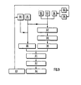
- the roll control law is integrated (1). From the trajectory thus obtained, we aim for points (2), we determine (3) the one for which the derivative of the cost is zero and the performance index is minimized, we calculate (4) the corridor constraints, roll angle and roll speed which the determined aiming point must satisfy, we determine (5) the four elementary control laws, we calculate (6) the weighting coefficients of these control laws, we determine (7 ) the global control law, we combine it (8) with the initial control law and we shift (9) the horizon by one shift step.
- a sensitivity calculation makes it possible to predict the effects of each elementary control law on the four parameters of performance index, lane, roll angle and roll speed. This results in a prediction matrix r, with, in rows, the parameters and, in columns, the laws.
- the performance of the method for determining the terrain avoidance and threat trajectory which has just been described is remarkable. It can bring a gain, in average altitude of terrain overflown, which can be several tens of meters, for an average lengthening of the distance traveled by Only 1%.
- the calculation horizon remains the same as that considered in determining the EVTM route.
- a vertex is said to be critical if, starting vertically from this zero-slope vertex, the other vertices on the working horizon can be overflown at zero slope after a series of nose-up phases with a minimum radius of curvature r c and a pricking phase with a minimum radius of curvature rp, the guard height being respected.
- the top 15 of the terrain profile 16, implying a working profile 17, is not a critical top, since the top 18, included in the working horizon, could not, after a rearing up and a dip at minimum radius, to be overflown at guard height and at zero slope.
- the flight trajectory at very low altitude in time space is determined.
Landscapes
- Engineering & Computer Science (AREA)
- Aviation & Aerospace Engineering (AREA)
- Radar, Positioning & Navigation (AREA)
- Remote Sensing (AREA)
- Physics & Mathematics (AREA)
- General Physics & Mathematics (AREA)
- Automation & Control Theory (AREA)
- Traffic Control Systems (AREA)
- Control Of Position, Course, Altitude, Or Attitude Of Moving Bodies (AREA)
Abstract
Description
L'environnement de menaces dans lequel les aéronefs, notamment les avions, doivent évoluer rend nécessaire le vol à très basse altitude pour permettre aux avions d'échapper au mieux à ces menaces et d'améliorer leurs performances tout au long de leurs missions.The threat environment in which aircraft, especially aircraft, must operate makes it necessary to fly at very low altitudes to allow planes to escape these threats as much as possible and improve their performance throughout their missions.
Au sol, une préparation de mission permet de définir un itinéraire de référence dans le plan horizontal.On the ground, a mission preparation makes it possible to define a reference route in the horizontal plane.
En vol, il faut générer en temps réel une trajectoire qui minimise l'altitude du terrain survolé et l'altitude de vol tout en respectant des contraintes de sécurité (hauteur de garde par rapport au sol), des contraintes de manoeuvrabilité (facteur de charge, angle et vitesse de roulis) et des contraintes opérationnelles (largeur de couloir).In flight, it is necessary to generate in real time a trajectory which minimizes the altitude of the terrain overflown and the flight altitude while respecting safety constraints (guard height above ground), maneuverability constraints (load factor , angle and roll speed) and operational constraints (lane width).
En d'autres termes, en vol, à partir de l'itinéraire de référence horizontal, on détermine, toujours dans le plan horizontal, une trajectoire à long terme d'évitement de terrain et de menaces, donc sa trace au sol et, enfin, un itinéraire à court terme dans un repère à deux dimensions x, y, dans un couloir centré sur la trajectoire d'évitement de terrain et de menaces. A partir du relief relevé dans ce couloir, on détermine, dans le plan vertical, une trajectoire à court terme de suivi de terrain qui, combinée à l'itinéraire à deux dimensions horizontales, fournit la trajectoire de vol à très basse altitude dans un système à quatre dimensions x, y, z, t.In other words, in flight, from the horizontal reference route, a long-term trajectory for avoiding terrain and threats, therefore its track on the ground and, finally, is determined in the horizontal plane. , a short-term route in a two-dimensional coordinate system x, y, in a corridor centered on the terrain avoidance and threats trajectory. From the relief found in this corridor, we determine, in the vertical plane, a short-term trajectory of ground following which, combined with the route with two horizontal dimensions, provides the flight trajectory at very low altitude in a system four-dimensional x, y, z, t.
Jusqu'à maintenant, on procédait dans le plan vertical en ménageant une marge de facteur de charge positif et une marge de facteur de charge négatif mais sans prendre en compte, ou mal, la variation de ce facteur de charge due à l'inclinaison de l'aéronef.Until now, we proceeded in the vertical plane by leaving a margin of positive load factor and a margin of negative load factor but without taking into account, or badly, the variation of this load factor due to the inclination of the aircraft.
Le facteur de charge est le rapport entre le poids apparent de l'avion et son poids réel et lorsque le facteur de charge devient trop important, il peut provoquer la déformation, voire même la rupture, de l'avion. Par convention, un avion subit un facteur de charge relatif positif, à cabrer, si son accélération tend à augmenter son poids apparent, et négatif, à piquer, si son accélération tend à le diminuer. Le facteur de charge augmente, non seulement lors d'une ressource, mais aussi en virage, avec l'inclinaison de l'avion.The load factor is the ratio between the apparent weight of the aircraft and its actual weight and when the load factor becomes too large, it can cause the aircraft to deform, even break. By convention, an aircraft undergoes a positive relative load factor, to pitch up, if its acceleration tends to increase its apparent weight, and negative, to pitch, if its acceleration tends to decrease it. The load factor increases, not only during a resource, but also when cornering, with the tilt of the aircraft.
Pour des raisons de confort du pilote ou de sécurité, le facteur de charge ne doit pas dépasser des valeurs maximales déterminées.For reasons of pilot comfort or safety, the load factor must not exceed determined maximum values.
Le facteur de charge est d'autant plus important que le rayon de courbure de la trajectoire est petit. Aux facteurs de charge maximaux positif et négatif, correspondent ainsi respectivement deux rayons de courbure minimaux.The load factor is all the more important the smaller the radius of curvature of the trajectory. The maximum positive and negative load factors therefore correspond respectively to two minimum radii of curvature.
Actuellement, pour la détermination de la trajectoire dans le plan vertical, on admet que les rayons de courbure minimaux sont constants et, avec eux, les accélérations verticales maximales. La détermination de la trajectoire de suivi de terrain se fonde sur une carte élaborée par un radar complétée éventuellement par des informations issues d'un fichier de cartes numérisées et, ce, sur un horizon à court terme d'une dizaine de kilomètres compatible avec la portée du radar. Sur l'horizon considéré, la vitesse de l'avion est supposée constante et la trajectoire est réactualisée en permanence. Les accélérations latérales, résultant des évolutions de l'avion dans le plan horizontal, ne sont prises en compte, dans les contraintes d'accélération verticale, que dans la limite d'accélérations maximales supposées constantes.Currently, for the determination of the trajectory in the vertical plane, it is assumed that the minimum radii of curvature are constant and, with them, the maximum vertical accelerations. The determination of the ground tracking trajectory is based on a map prepared by a radar possibly supplemented by information from a file of digitized maps, and this, over a short-term horizon of ten kilometers compatible with the radar range. Over the horizon considered, the speed of the aircraft is assumed to be constant and the trajectory is constantly updated. The lateral accelerations, resulting from the evolution of the airplane in the horizontal plane, are taken into account, in the vertical acceleration constraints, only within the limit of maximum accelerations assumed to be constant.
Pouvoir respecter les contraintes de facteur-de charge avec des contraintes d'accélération verticale variables et pouvoir ainsi anticiper les phases à cabrer avant un virage pour minimiser la hauteur de vol, tel est l'objectif de la présente invention.Being able to respect the load factor constraints with variable vertical acceleration constraints and thus be able to anticipate the nose-up phases before a turn to minimize the flight height, such is the objective of the present invention.
A cet effet, la présente invention concerne un procédé de pilotage à très basse altitude d'un aéronef pouvant subir un facteur de charge maximal à cabrer et un facteur de charge maximal à piquer, dans lequel on détermine en vol une trajectoire horizontale d'évitement de terrain et de menaces EVTM, correspondant à une loi de commande en roulis, puis une trajectoire verticale de suivi de terrain SDT, correspondant à une loi de commande en accélération verticale,caractérisé par le fait qu'on détermine les accélérations latérales de l'aéronef sur la trajectoire horizontale EVTM et que les portions à cabrer de la trajectoire verticale SDT sont déterminées par la marge de facteur de charge à cabrer laissée disponible par les accélérations latérales sur la trajectoire EVTM.To this end, the present invention relates to a method of piloting at an very low altitude an aircraft capable of undergoing a maximum load factor to pitch up and a maximum load factor to dive, in which a horizontal avoidance trajectory is determined in flight of terrain and threats EVTM, corresponding to a roll control law, then a vertical track trajectory SDT, corresponding to a control law in vertical acceleration, characterized by the fact that the lateral accelerations of the aircraft on the horizontal EVTM trajectory and that the nose-up portions of the vertical trajectory SDT are determined by the nose-up load factor margin left available by lateral accelerations on the EVTM trajectory.
Avantageusement,
- - les portions à cabrer de la trajectoire SDT sont déterminées pour que l'aéronef soit soumis à une accélération verticale telle qu'il subisse le facteur de charge maximal à cabrer,
- - les portions à piquer de la trajectoire SDT sont déterminées pour que l'avion subisse le facteur de charge maximal à piquer,
- - pour déterminer les portions à piquer de la trajectoire SDT, on isole sur un horizon de travail des sommets critiques à survoler à une hauteur de garde et à pente nulle,
- - les portions à piquer de la trajectoire SDT sont circulaires et tangentes aux sommets critiques,
- - pour déterminer la trajectoire EVTM, on minimise un indice de performance constitué de l'intégrale d'un indice de coût

- - la loi de commande élémentaire de minimisation de l'indice de coût est déterminée en découpant la trajectoire EVTM en pas de visée, sur chacun desquels on vise le point, écarté de l'itinéraire de référence de Y, qui annule la dérivée première, par rapport à la variable Y, de l'indice de coût, en déterminant le lieu des points ainsi visés, qui est la courbe d'équation

- - the nose-up portions of the SDT trajectory are determined so that the aircraft is subjected to vertical acceleration such that it undergoes the maximum load factor to be nose-up,
- - the portions to be stung of the SDT trajectory are determined so that the aircraft undergoes the maximum load factor to be stung,
- - in order to determine the portions to be stung of the SDT trajectory, critical vertices to be overflown at a guard height and at zero slope are isolated on a working horizon,
- - the stinging portions of the SDT trajectory are circular and tangent to the critical vertices,
- - to determine the EVTM trajectory, we minimize a performance index made up of the integral of a cost index
- the elementary control law for minimizing the cost index is determined by cutting the EVTM trajectory into no target, on each of which the point is aimed, removed from the reference route of Y, which cancels the first derivative, with respect to variable Y, of the cost index, by determining the location of the points thus targeted, which is the equation curve
La détermination en vol de la trajectoire horizontale d'évitement de terrain et de menaces EVTM étant particulièrement importante pour la mise en oeuvre du procédé de pilotage à très basse altitude de l'invention, la demanderesse entend également revendiquer les caractéristiques essentielles de cette détermination de trajectoire EVTM en tant que telles.Since the determination in flight of the horizontal trajectory for avoiding terrain and EVTM threats is particularly important for the implementation of the very low altitude piloting method of the invention, the applicant also intends to claim the essential characteristics of this determination of EVTM trajectory as such.
L'invention sera mieux comprise à l'aide de la description suivante de la mise en oeuvre préférée du procédé de pilotage d'un avion, conforme à l'invention, en référence aux dessins annexés, sur lesquels
- - la figure 1 représente un profil de relief dans un plan perpendiculaire à un itinéraire de référence et illustre l'écartement de l'avion de cet itinéraire pour éviter le terrain;
- - la figure 2 représente un profil de relief et illustre l'étape des points visés du procédé de pilotage de l'invention;
- - la figure 3 illustre schématiquement les étapes de détermination en vol de la trace au sol d'évitement de terrain et de menaces;
- - la figure 4 illustre très schématiquement les étapes de détermination en vol de la trajectoire de suivi de terrain;
- - la figure 5 représente un profil de relief dans le plan de suivi de terrain et illustre la détermination des sommets critiques;
- - la figure 6 représente les portions de trajectoire à piquer de la trajectoire verticale de suivi de terrain;
- - la figure 7 illustre la loi de commande élémentaire à piquer de la gouverne de profondeur de l'avion;
- - la figure 8 illustre la loi globale d'accélération verticale de suivi de terrain et
- - la figure 9 illustre les étapes de détermination en vol de la trajectoire de suivi de terrain.
- - Figure 1 shows a relief profile in a plane perpendicular to a reference route and illustrates the spacing of the aircraft from this route to avoid the terrain;
- - Figure 2 shows a relief profile and illustrates the step of the targeted points of the piloting method of the invention;
- - Figure 3 schematically illustrates the steps for determining in flight the ground trace of terrain avoidance and threats;
- - Figure 4 illustrates very schematically the steps of determining in flight the ground following trajectory;
- - Figure 5 shows a relief profile in the ground monitoring plan and illustrates the determination of critical peaks;
- FIG. 6 represents the portions of trajectory to be stung from the vertical trajectory for following terrain;
- - Figure 7 illustrates the elementary control law to stitch the elevator of the aircraft;
- FIG. 8 illustrates the global law of vertical acceleration of ground tracking and
- - Figure 9 illustrates the steps for determining in flight the ground following trajectory.
Le procédé, qui va être décrit, permet de déterminer la loi de commande en roulis et la loi de commande en accélération verticale d'un aéronef, en l'occurence un avion, lois qui, combinées, forment des lois de commande des ailerons et des gouvernes de profondeur pour que l'avion suive, de façon globale, une trajectoire à très basse altitude.The method, which will be described, makes it possible to determine the roll control law and the vertical acceleration control law of an aircraft, in this case an airplane, laws which, combined, form aileron control laws and elevators so that the aircraft generally follows a trajectory at very low altitude.
Il doit être précisé que par gouverne de profondeur on entend également toute gouverne équivalente et que par aileron on entend toute gouverne de gauchissement. En outre, les lois de commande dont il s'agit ne sont naturellement pas celles qui commandent directement la gouverne de profondeur et les ailerons; ce sont des lois qui permettent d'élaborer des ordres de commande de gouverne.It should be clarified that by elevator is also meant any equivalent and that by fin means any warping. Furthermore, the control laws in question are naturally not those which directly control the elevator and the ailerons; these are laws which make it possible to draw up control orders.
Cette trace au sol, donc dans un plan horizontal, doit minimiser l'altitude du terrain survolé, pour profiter au mieux des masques offerts par les reliefs, sans pour autant trop s'écarter de l'itinéraire de référence déterminé au sol lors de la préparation de la mission. Si on considère que l'avion, à un instant donné, et selon l'itinéraire élaboré au sol, devrait se trouver en A, dans un plan vertical P, au dessus d'un relief R, la trace d'évitement l'écartera latéralement du plan P pour l'amener en B, au-dessus d'un thalweg T (figure 1). Cette trace au sol minimise, pendant toute la navigation, un indice de performance qui intègre l'altitude du terrain Z et l'écart latéral Y par rapport à l'itinéraire de référence, cet indice étant pondéré par un coefficient K permettant de moduler l'importance accordée à la fonction d'évitementThis track on the ground, therefore in a horizontal plane, must minimize the altitude of the terrain overflown, to make the most of the masks offered by the reliefs, without however deviating too much from the reference route determined on the ground during the mission preparation. If we consider that the plane, at a given instant, and according to the route developed on the ground, should be at A, in a vertical plane P, above a relief R, the avoidance trace will remove it laterally from plane P to bring it to B, above a thalweg T (Figure 1). This track on the ground minimizes, during all navigation, a performance index which integrates the altitude of the terrain Z and the lateral deviation Y from the reference route, this index being weighted by a coefficient K making it possible to modulate the importance given to the avoidance function
La détermination de la trace au sol doit intégrer des contraintes :
- - limites de l'angle de roulis, ou inclinaison,
- - limites de la vitesse de roulis,
- - zones de vol ou couloirs autorisés, en écarts latéraux maximaux par rapport à l'itinéraire de référence.
- . L'itinéraire de référence, ou plan de vol horizontal, est découpé en segments de navigation.
- - limits of the roll angle, or inclination,
- - rolling speed limits,
- - authorized flight zones or corridors, in maximum lateral deviations from the reference route.
- . The reference route, or horizontal flight plan, is divided into navigation segments.
La génération en vol de la trajectoire au sol s'effectue par segment d'optimisation correspondant à l'horizon de calcul. Une fois la trajectoire d'un serpent d'optimisation déterminée, l'horizon de calcul glisse le long de l'itinéraire de référence et le serpent d'optimisation adjacent est traité. . A l'itinéraire de référence, correspond une loi de commande des ailerons de l'appareil, c'est-à-dire une loi de commande en roulis. Déterminer en vol la trace d'évitement, c'est déterminer les lois des variations à appliquer à la loi de commande en roulis pour minimiser l'indice de performance en respectant les contraintes.The flight path generation on the ground is performed by optimization segment corresponding to the horizon Calculation. Once the trajectory of an optimization snake has been determined, the calculation horizon slides along the reference route and the adjacent optimization snake is processed. . The reference route corresponds to a control law for the ailerons of the apparatus, that is to say a roll control law. To determine in flight the avoidance trace is to determine the laws of variations to be applied to the roll control law to minimize the performance index while respecting the constraints.
. Il est représenté par la fonction intégrale
- to est l'instant de survol de l'origine du segment d'optimisation,
- tf est l'instant de survol de la fin du segment d'optimisation,
- Z est l'altitude du terrain survolé à l'instant t,
- Y est l'écart latéral entre la position de l'avion et l'itinéraire de référence à l'instant t,
- K est le coefficient de pondération évoqué plus haut.
- En fait, K pondère les écarts latéraux. Si K est faible, le poids des écarts latéraux est minoré et l"évitement" est donc favorisé. Si K est fort, le poids des écarts latéraux est majoré et l'évitement est donc pénalisé par rapport au suivi de l'itinéraire de référence.
- t o is the instant overflight of the origin of the optimization segment,
- t f is the flyover instant of the end of the optimization segment,
- Z is the altitude of the terrain overflown at time t,
- Y is the lateral deviation between the position of the airplane and the reference route at time t,
- K is the weighting coefficient mentioned above.
- In fact, K weights the lateral deviations. If K is small, the weight of the lateral deviations is reduced and "avoidance" is therefore favored. If K is strong, the weight of the lateral deviations is increased and the avoidance is therefore penalized compared to following the reference route.
. Chaque segment d'optimisation est découpé en pas de visée élémentaire, sur chacun desquels on détermine-on vise-à un instant donné t le point de coordonnées X, Y qui annule la dérivée première par rapport à la variable Y, du terme intégré de l'indice de performance, appelé coût,![]()
![]()
Le lieu des points visés, sur chaque segment d'optimisation est la courbe d'équation![]()
![]()
![]()
![]()
![]()
![]()
A partir de la fonction Y(t), on détermine facilement, par triple dérivation par rapport au temps, la loi de commande élémentaire Y (t) de vitesse de roulis à appliquer à la loi de commande en roulis initiale de l'itinéraire de référence pour faire passer l'avion au-dessus des points visés.From the function Y (t), the elementary control law Y (t) of roll speed to be applied to the initial roll control law of the route of the route is easily determined by triple derivation with respect to time. reference for passing the aircraft over the target points.
Un couloir étant défini par sa largeur 2ymax la contrainte de couloir se traduit par la double relation![]()
![]()
La contrainte de vitesse de roulis se traduit par la relation![]()
![]()
A partir de cette relation, il est facile, par détermination des écarts, de déterminer directement la loi de commande élémentaire Y" (t) de roulis à appliquer à la loi de commande en roulis.From this relation, it is easy, by determining the deviations, to directly determine the elementary control law Y "(t) of roll to be applied to the roll control law.
La vitesse de roulis est proportionnelle à la dérivée première de l'angle de roulis qui, lui-même est proportionnel à la dérivée première du cap, qui lui-même est proportionnel à la dérivée première de l'écart latéral Y. La contrainte d'angle de roulis se traduit par la double relation![]()
![]()
A partir de cette double relation, il est facile, par détermination des écarts, de déterminer, d'abord, la fonc- fion élémentaire de la variation d'angle à appliquer pour respecter la contrainte puis, par simple dérivation, la loi de commande élémentaire Y''' (t) de roulis à appliquer à la loi de commande en roulis.From this double relation, it is easy, by determining the deviations, to determine, first, the elementary function of the angle variation to be applied in order to respect the constraint, then, by simple derivation, the control law elementary Y '' '(t) of roll to apply to the roll control law.
En définitive, l'avion doit évoluer dans le plan horizontal en minimisant l'indice de performance et sous trois contraintes, aboutissant à quatre lois de commande élémentaires de vitesse de roulis![]()
![]()
Schématiquement, et en référence à la figure 3, le procédé de détermination en vol de la trace au sol d'évitement de terrain et de menaces se déroule, à chaque pas de visée, comme indiqué ci-après.Schematically, and with reference to FIG. 3, the method for determining in flight the ground track of terrain avoidance and threats takes place, at each aiming step, as indicated below.
A chaque point de calcul sur un pas, d'intégration de la trajectoire,ici de l'ordre de deux cent cinquante mètres,la loi de commande en roulis est intégrée (1). A partir de la trajectoire ainsi obtenue, on vise des points (2), on détermine (3) celui pour lequel la dérivée du coût s'annule et l'indice de performance est minimisé, on calcule (4) les contraintes de couloir, d'angle de roulis et de vitesse de roulis auxquelles le point de visée déterminé doit satisfaire, on détermine (5) les quatre lois de commande élémentaires, on calcule (6) les coefficients de pondération de ces lois de commande, on détermine (7) la loi de commande globale, on la combine (8) à la loi de commande initiale et on décale (9) l'horizon d'un pas de décalage.At each point of calculation of a step, of integration of the trajectory, here of the order of two hundred and fifty meters, the roll control law is integrated (1). From the trajectory thus obtained, we aim for points (2), we determine (3) the one for which the derivative of the cost is zero and the performance index is minimized, we calculate (4) the corridor constraints, roll angle and roll speed which the determined aiming point must satisfy, we determine (5) the four elementary control laws, we calculate (6) the weighting coefficients of these control laws, we determine (7 ) the global control law, we combine it (8) with the initial control law and we shift (9) the horizon by one shift step.
Un algorithme est utilisé pour le calcul des coefficients de pondération, compris entre 0 et 1, des lois de commande élémentaires qui sont ensuite combinées en un polynome linéaire.An algorithm is used for the calculation of the weighting coefficients, between 0 and 1, of the elementary control laws which are then combined into a linear polynomial.
Un calcul de sensibilité permet de prévoir les effets de chaque loi de commande élémentaire sur les quatre paramètres d'indice de performance, de couloir, d'angle de roulis et de vitesse de roulis. Il en résulte une matrice de prédiction r , avec, en lignes, les paramètres et, en colonnes, les lois.A sensitivity calculation makes it possible to predict the effects of each elementary control law on the four parameters of performance index, lane, roll angle and roll speed. This results in a prediction matrix r, with, in rows, the parameters and, in columns, the laws.
Pour que les prédictions soient validées, la relation suivante, représentative du gradient projeté, doit être satisfaite :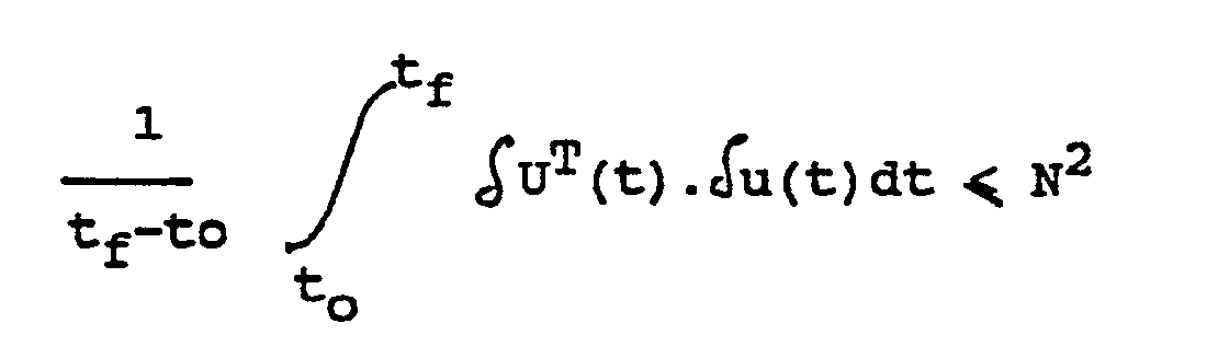
On tire de cette relation d'abord le vecteur des variations prévues des quatre paramètres δVp puis le vecteur des coefficients de pondération µ (K, Ki, K2, K3) donné par la relation![]()
![]()
![]()
![]()
Incidemment, les performances du procédé de détermination de la trajectoire d'évitement de terrain et de menaces qui vient d'être décrit sont remarquables. Il peut apporter un gain, en altitude moyenne de terrain survolé, qui peut être de plusieurs dizaines de mètres, pour un allongement moyen de la distance parcourue de 1 % seulement.Incidentally, the performance of the method for determining the terrain avoidance and threat trajectory which has just been described is remarkable. It can bring a gain, in average altitude of terrain overflown, which can be several tens of meters, for an average lengthening of the distance traveled by Only 1%.
Lorsqu'un avion, à partir d'une trajectoire rectiligne en palier, subit des forces déviatrices dans le plan horizontal et dans le plan vertical, avec une accélération horizontale (latérale) Y(t) et une accélération verticale Z (t), il est soumis à un facteur de charge Jz, souvent noté nzxg, satisfaisant la relation![]()
![]()
Les trajectoires de suivi de terrain doivent assurer la sécurité de l'avion par rapport au sol et respecter certaines contraintes :
- - hauteur de garde minimale par rapport au sol,
- - hauteur de vol minimale,
- - passage de sommets à la hauteur de garde et à pente nulle,
- - contraintes d'accélérations verticales maximales à cabrer et à piquer,
- - contraintes opérationnelles.
- - minimum guard height from the ground,
- - minimum flight height,
- - passage from vertices to guard height and zero slope,
- - maximum vertical acceleration constraints to pitch up and to pitch,
- - operational constraints.
Les évolutions d'un avion dans le plan vertical en suivi de terrain SDT, selon le procédé de l'invention, sont liées à celles effectuées dans le plan horizontal en évitement de terrain et de menaces EVTM par le facteur de charge Jz. Pour les évolutions à cabrer, la contrainte à prendre en compte est la marge de facteur de charge, en
Globalement, et en référence à la figure 4, la trajectoire SDT est donc déterminée (13), et l'avion ainsi piloté, en
- - déterminant (10) la trajectoire EVTM, comme décrit plus haut,
- - calculant (11) la valeur de l'accélération latérale
Y sur la trajectoire EVTM et - - calculant (12) la valeur de l'accélération verticale Z max disponible pour ne pas dépasser les facteurs de charge Jz max à cabrer et à Jz max à piquer.
- - determining (10) the EVTM trajectory, as described above,
- - calculating (11) the value of lateral acceleration
Y on the EVTM trajectory and - - calculating (12) the value of the vertical acceleration Z max available so as not to exceed the load factors J z max to pitch up and at J z max to pitch.
Le procédé de détermination de la trajectoire SDT repose sur les choix suivants :
- - les phases à piquer doivent minimiser la hauteur de vol et être exécutées le plus possible au facteur de charge maximal à piquer,
- - les phases à cabrer doivent maintenir l'avion au moins à la hauteur de garde et ufilisertoute l'accélération verticale disponible pour que l'avion subisse le facteur de charge maximal à cabrer.
- - the phases to be stuck must minimize the flight height and be carried out as much as possible at the maximum load factor to be stung,
- - the nose-up phases must keep the airplane at least at guard height and use all the vertical acceleration available so that the airplane experiences the maximum load factor for nose-up.
Cette détermination de trajectoire SDT comprend les étapes de
- - détermination d'un profil de travail,
- - recherche de sommets critiques,
- - détermination des trajectoires à piquer autour des sommets critiques,
- - détermination des trajectoires à cabrer.
- - determination of a work profile,
- - search for critical peaks,
- - determination of the trajectories to be stuck around the critical peaks,
- - determination of the nose-up trajectories.
Il s'agit du profil vertical du terrain à survoler, décalé vers le haut de la hauteur de garde.This is the vertical profile of the terrain to be overflown, shifted upwards from the guard height.
Il est déterminé par
- - l'itinéraire d'évitement de terrain et de menaces EVTM préalablement déterminé,
- - un radar,
- - un fichier de cartes.
- - the route of terrain avoidance and EVTM threats previously determined,
- - a radar,
- - a card file.
L'horizon de calcul reste le même que celui considéré dans la détermination de l'itinéraire EVTM.The calculation horizon remains the same as that considered in determining the EVTM route.
Il s'agit des sommets pouvant être survolés à la hauteur de garde et à pente nulle, les contraintes de manoeuvrabilité étant naturellement prises en compte.These are the vertices that can be overflown at guard height and at zero slope, the maneuverability constraints being naturally taken into account.
Un sommet est dit critique si, en partant à la verticale de ce sommet à pente nulle, les autres sommets sur l'horizon de travail peuvent être survolés à pente nulle après enchaînement d'une phase à cabrer à rayon de courbure minimal rc et d'une phase à piquerà rayon de courbure minimal rp, la hauteurde garde étant respectée.A vertex is said to be critical if, starting vertically from this zero-slope vertex, the other vertices on the working horizon can be overflown at zero slope after a series of nose-up phases with a minimum radius of curvature r c and a pricking phase with a minimum radius of curvature rp, the guard height being respected.
En référence à la figure 5, le sommet 15 du profil de terrain 16, impliquant un profil de travail 17, n'est pas un sommet critique, puisque le sommet 18, compris dans l'horizon de travail, ne pourrait pas, après un cabrer et un piquer à rayons minimaux, être survolé à la hauteur de garde et à pente nulle.With reference to FIG. 5, the top 15 of the
Si D est la distance de l'obstacle (18) au sommet considéré (15) et si on pose R = rc + rp, un sommet est considéré comme critique si aucun sommet sur l'horizon de travail ne dépasse de la courbe d'équation![]()
![]()
Les sommets critiques, par définition, sont vus par le radar et les portions de relief non visibles par lui, ou tout autre capteur frontal, ne peuvent pas affecter le procédé de détermination de l'invention.The critical peaks, by definition, are seen by the radar and the relief portions not visible to it, or any other frontal sensor, cannot affect the method of determining the invention.
Il s'agit de former autour des sommets critiques 20, 21, en remplacement du profil de travail 22 (figure 6), des trajectoires circulaires 23, 24 tangentes aux sommets 20, 21 et de rayon égal au rayon minimal à piquer, si le terrain est suffisamment accidenté. Dans le cas contraire, on adopte le rayon de courbure du relief comme rayon de trajectoire circulaire. En d'autres termes, pour obtenir les meilleures performances en hauteur de vol, il faut chercher à exécuter des phases à piquer le plus souvent possible tout en s'assurant que lors des phases à cabrer la hauteur de garde et les contraintes d'accélération verticale sont respectées.This involves forming around the
A cet effet, on intègre la trajectoire pas à pas autour de chaque sommet critique :![]()
![]()
![]()
![]()
La loi de commande élémentaire en accélération verticale, illustrée parla courbe 25 surlafigure 7, possède la double particularité d'être quasiment constante, avec une accélération négative égale à l'accélération maximale à piquer, sauf aux intersections des portions de trajectoires circulaires, où elle présente des pics d'accélération positive nettement supérieurs à l'accélération à cabrer disponible et qu'il faut écreter.The elementary law of control in vertical acceleration, illustrated by
D'après la relation donnant le facteur de charge Jz, l'accélération maximale à cabrer disponible est égale à
On admet ici encore que l'accélération est constante le long d'un pas de calcul.It is also admitted here that the acceleration is constant along a calculation step.
A l'aide de la loi de commande Z (t)max à cabrer, illustrée par la courbe 26 sur la figure 7, à laquelle on compare la loi de commande élémentaire de la courbe 25 de la figure 7, on détecte les dépassements de l'accélération verticale à cabrer disponible.Using the control law Z (t) max to pitch up, illustrated by
Pour chaque dépassement, on définit un intervalle de travail, le long duquel on applique une correction. A cet effet, on détermine de nouveaux instants de début T1(m1) et de fin T2(m2) de phase à cabrer pour que
- - le dépassement soit réparti de façon symétrique en-deçà du maximum d'accélération verticale disponible sur l'intervalle de travail considéré,
- - la vitesse Z(t) et l'altitude Z(t) de l'avion à ces deux instants soient respectivement les mêmes.
- - the overshoot is distributed symmetrically below the maximum vertical acceleration available over the working interval considered,
- - the speed Z (t) and the altitude Z (t) of the airplane at these two times are respectively the same.
Il s'agit, donc de résoudre de façon simple un système de deux équations à deux inconnues T1' T2.It is therefore a question of solving in a simple way a system of two equations with two unknowns T 1 ' T 2 .
En cas d'interférence de plusieurs dépassements, on élargit l'intervalle de travail.In the event of interference from several exceedances, the working interval is widened.
On en déduit une loi de commande élémentaire d'accélération verticale à cabrer, annulant les dépassements sur l'horizon de travail et qui, combinée à la loi de commande élémentaire d'accélération verticale à piquer fournit, pour la commande automatique de la gouverne de profondeur de l'avion, la loi globale d'accélération verticale de suivi de terrain illustrée par la courbe 27 de la figure 8.We deduce therefrom an elementary vertical acceleration control law to pitch up, canceling the overshoots on the working horizon and which, combined with the elementary vertical acceleration control law to pitch, provides, for the automatic control of the control surface depth of the aircraft, the global law of vertical acceleration of ground following illustrated by
Grâce à cela, la hauteur de garde et donc la sécurité de l'avion sont respectées. Même si l'évitement de terrain et de menaces a absorbé une partie du facteur de charge, les accélérations à cabrer vont être produites plus tôt qu'elles ne l'auraient été si l'avion avait volé à inclinaison nulle.Thanks to this, the guard height and therefore the safety of the aircraft are respected. Even if terrain and threat avoidance have absorbed part of the load factor, nose-up accelerations will be produced sooner than they would have been if the plane had flown at zero tilt.
La loi d'accélération verticale Z (t) étant déterminée, la trajectoire SDT en découle par une double intégration![]()
![]()
Une fois les trajectoires EVTM et SDT déterminées, la trajectoire de vol à très basse altitude dans l'espace temps est déterminée.Once the EVTM and SDT trajectories are determined, the flight trajectory at very low altitude in time space is determined.
En définitive, et en référence à la figure 9, le pilotage de l'avion en suivi de terrain à très basse altitude comporte les étapes suivantes :
- - la trajectoire d'évitement de terrain et de menaces EVTM ayant été déterminée (63) et les accélérations latérales en EVTM calculées (50), le facteur de charge maximal à cabrer étant connu (51), tout comme le facteur de charge maximal à piquer (52) et la hauteur de garde (53), à partir d'une carte de terrain (54) établie à partir des informations du radar (55) et éventuellement d'un fichier de cartes (56).
- - on recherche les sommets critiques sur l'horizon de travail (57),
- - on forme autour des sommets critiques les portions de trajectoire circulaires au rayon minimal à piquer (58),
- - on en détermine la loi de commande élémentaire pour les phases à piquer (59),
- - on calcule l'accélération verticale maximale à cabrer disponible (60),
- - on détermine la loi de commande élémentaire pour les phases à cabrer (61),
- - on détermine la loi de commande globale de la gouverne de profondeur (62),
- - on en détermine la trajectoire de suivi de terrain (64).
- - the terrain avoidance and EVTM threat trajectory having been determined (63) and the lateral accelerations in EVTM calculated (50), the maximum load factor to pitch up being known (51), as is the maximum load factor at dive (52) and the guard height (53), from a terrain map (54) established on the basis of radar information (55) and possibly from a map file (56).
- - we are looking for critical peaks on the work horizon (57),
- - the circular trajectory portions with the minimum radius to be stitched are formed around the critical vertices (58),
- - the elementary control law for the phases to be stitched in is determined (59),
- - the maximum vertical acceleration available to pitch up is calculated (60),
- - the elementary control law for the pitch-up phases is determined (61),
- - the overall control law of the elevator (62) is determined,
- - the ground tracking trajectory (64) is determined.
Les intérêts du procédé qui vient d'être décrit sont nombreux.The advantages of the process which has just been described are numerous.
La trajectoire de suivi de terrain respecte toujours la hauteur de garde et la hauteur de vol est minimisée. Les sommets des reliefs sont survolés à pente rigoureusement nulle et exactement à la hauteur de garde : la vulnérabilité de l'avion est donc réduite au mieux.The terrain following trajectory always respects the guard height and the flight height is minimized. The peaks of the reliefs are flown over at a strictly zero slope and exactly at guard height: the vulnerability of the aircraft is therefore reduced at best.
Claims (17)
Applications Claiming Priority (2)
| Application Number | Priority Date | Filing Date | Title |
|---|---|---|---|
| FR9002182 | 1990-02-22 | ||
| FR9002182A FR2658636B1 (en) | 1990-02-22 | 1990-02-22 | PROCESS FOR THE PILOTAGE OF AN AIRCRAFT IN FLIGHT AT VERY LOW ALTITUDE. |
Publications (2)
| Publication Number | Publication Date |
|---|---|
| EP0453327A1 true EP0453327A1 (en) | 1991-10-23 |
| EP0453327B1 EP0453327B1 (en) | 1996-05-01 |
Family
ID=9394018
Family Applications (1)
| Application Number | Title | Priority Date | Filing Date |
|---|---|---|---|
| EP91400342A Expired - Lifetime EP0453327B1 (en) | 1990-02-22 | 1991-02-12 | Method of guiding an airborne vehicle on a very low altitude flight path |
Country Status (3)
| Country | Link |
|---|---|
| EP (1) | EP0453327B1 (en) |
| DE (1) | DE69119139T2 (en) |
| FR (1) | FR2658636B1 (en) |
Cited By (8)
| Publication number | Priority date | Publication date | Assignee | Title |
|---|---|---|---|---|
| EP0655699A1 (en) * | 1993-11-30 | 1995-05-31 | Honeywell Inc. | Mission planning cost system |
| GB2310184A (en) * | 1996-02-19 | 1997-08-20 | Marconi Gec Ltd | Terrain advisory system for aircraft |
| FR2747492A1 (en) * | 1996-04-15 | 1997-10-17 | Dassault Electronique | TERRAIN ANTI-COLLISION DEVICE FOR AIRCRAFT WITH TURN PREDICTION |
| FR2868835A1 (en) * | 2004-04-09 | 2005-10-14 | Thales Sa | METHOD FOR SELECTING, FOR AN AIRCRAFT, A POINT OF ACCESS TO A FREE ZONE OF LATERAL EVOLUTION |
| FR2870606A1 (en) * | 2004-05-18 | 2005-11-25 | Airbus France Sas | METHOD AND DEVICE FOR SECURING A LOW ALTITUDE FLIGHT OF AN AIRCRAFT |
| US7853369B2 (en) * | 2006-12-05 | 2010-12-14 | Airbus France | Active pitch control method and device for an aircraft |
| CN101111809B (en) * | 2005-01-31 | 2012-07-04 | 空中巴士公司 | Method and device for constructing a low-altitude flight path to be followed by an aircraft |
| CN114115332A (en) * | 2021-10-29 | 2022-03-01 | 北京星途探索科技有限公司 | Ground sweeping flight technology applied to short-range supersonic speed cruise bomb |
Families Citing this family (7)
| Publication number | Priority date | Publication date | Assignee | Title |
|---|---|---|---|---|
| DE4436356B4 (en) * | 1994-10-12 | 2007-10-31 | Airbus Deutschland Gmbh | Method for route generation |
| FR2741320B1 (en) * | 1995-11-21 | 1998-01-02 | Sextant Avionique | LOW ALTITUDE PILOTAGE PROCESS |
| JP3645038B2 (en) * | 1996-07-05 | 2005-05-11 | 富士重工業株式会社 | Aircraft flight control equipment |
| IL159893A (en) * | 2004-01-15 | 2008-11-26 | Rafael Advanced Defense Sys | Method of terrain following |
| FR2887065B1 (en) * | 2005-06-14 | 2007-07-20 | Airbus France Sas | METHOD AND SYSTEM FOR AIDING THE STEERING OF A LOW ALTITUDE FLYING AIRCRAFT |
| FR2947370B1 (en) | 2009-06-26 | 2011-11-25 | Eurocopter France | METHOD FOR ASSISTING LOW ALTITUDE DRIVING |
| FR2962838B1 (en) | 2010-07-16 | 2012-07-13 | Eurocopter France | IMPROVED AIRCRAFT ASSISTING AID METHOD |
Citations (5)
| Publication number | Priority date | Publication date | Assignee | Title |
|---|---|---|---|---|
| US3530465A (en) * | 1957-07-10 | 1970-09-22 | Sperry Rand Corp | Obstacle clearance system for aircraft |
| US4302745A (en) * | 1980-01-10 | 1981-11-24 | The United States Of America As Represented By The Secretary Of The Air Force | Aircraft load factor overload warning system |
| EP0083569A1 (en) * | 1982-01-04 | 1983-07-13 | General Electric Company | Large angle, gravity compensated, bank-to-turn pursuit controller |
| EP0234237A1 (en) * | 1986-02-12 | 1987-09-02 | Messerschmitt-Bölkow-Blohm Gesellschaft mit beschränkter Haftung | Low altitude flying method for automatically determining the flight path |
| FR2607948A1 (en) * | 1986-12-09 | 1988-06-10 | Dassault Electronique | Terrain avoidance method and device for aircraft |
-
1990
- 1990-02-22 FR FR9002182A patent/FR2658636B1/en not_active Expired - Fee Related
-
1991
- 1991-02-12 DE DE69119139T patent/DE69119139T2/en not_active Expired - Fee Related
- 1991-02-12 EP EP91400342A patent/EP0453327B1/en not_active Expired - Lifetime
Patent Citations (5)
| Publication number | Priority date | Publication date | Assignee | Title |
|---|---|---|---|---|
| US3530465A (en) * | 1957-07-10 | 1970-09-22 | Sperry Rand Corp | Obstacle clearance system for aircraft |
| US4302745A (en) * | 1980-01-10 | 1981-11-24 | The United States Of America As Represented By The Secretary Of The Air Force | Aircraft load factor overload warning system |
| EP0083569A1 (en) * | 1982-01-04 | 1983-07-13 | General Electric Company | Large angle, gravity compensated, bank-to-turn pursuit controller |
| EP0234237A1 (en) * | 1986-02-12 | 1987-09-02 | Messerschmitt-Bölkow-Blohm Gesellschaft mit beschränkter Haftung | Low altitude flying method for automatically determining the flight path |
| FR2607948A1 (en) * | 1986-12-09 | 1988-06-10 | Dassault Electronique | Terrain avoidance method and device for aircraft |
Non-Patent Citations (2)
| Title |
|---|
| IEEE 1988 NATIONAL AEROSPACE AND ELECTRONICS CONFERENCE NAECON 1988 vol. 2, 23-27 mai 1988, pages 540-545, Dayton Convention Center, US; A. WEIMANN et al.: "Terrain Masking and Threat Avoidance Using Land Mass Data" * |
| PROCEEDINGS OF THE 1988 AMERICAN CONTROL CONFERENCE vol. 2, 15-17 juin 1988, pages 1440-1447, Atlanta Hilton Hotel, Atlanta, US; P.K.A. MENON et al.: "Helicopter Trajectory Planning Using Optimal Control Theory" * |
Cited By (16)
| Publication number | Priority date | Publication date | Assignee | Title |
|---|---|---|---|---|
| EP0655699A1 (en) * | 1993-11-30 | 1995-05-31 | Honeywell Inc. | Mission planning cost system |
| EP0655698A1 (en) * | 1993-11-30 | 1995-05-31 | Honeywell Inc. | Low level flight flyability transformation of digital terrain elevation data |
| GB2310184A (en) * | 1996-02-19 | 1997-08-20 | Marconi Gec Ltd | Terrain advisory system for aircraft |
| GB2310184B (en) * | 1996-02-19 | 2000-10-11 | Marconi Gec Ltd | Aircraft terrain advisory system |
| FR2747492A1 (en) * | 1996-04-15 | 1997-10-17 | Dassault Electronique | TERRAIN ANTI-COLLISION DEVICE FOR AIRCRAFT WITH TURN PREDICTION |
| EP0802469A1 (en) * | 1996-04-15 | 1997-10-22 | Dassault Electronique | Device for aircraft ground collision avoidance with turn prediction |
| US6480120B1 (en) | 1996-04-15 | 2002-11-12 | Dassault Electronique | Airborne terrain collision prevention device with prediction of turns |
| WO2005109138A1 (en) * | 2004-04-09 | 2005-11-17 | Thales | Method for selecting aircraft access point into a lateral free evolution area |
| FR2868835A1 (en) * | 2004-04-09 | 2005-10-14 | Thales Sa | METHOD FOR SELECTING, FOR AN AIRCRAFT, A POINT OF ACCESS TO A FREE ZONE OF LATERAL EVOLUTION |
| US8032266B2 (en) | 2004-04-09 | 2011-10-04 | Thales | Method for selecting aircraft access point into a lateral free evolution area |
| FR2870606A1 (en) * | 2004-05-18 | 2005-11-25 | Airbus France Sas | METHOD AND DEVICE FOR SECURING A LOW ALTITUDE FLIGHT OF AN AIRCRAFT |
| EP1600838A1 (en) * | 2004-05-18 | 2005-11-30 | Airbus France | Method and apparatus for securing low altitude flight of an aircraft |
| US7428451B2 (en) | 2004-05-18 | 2008-09-23 | Airbus France | Method and device for ensuring the safety of a low-altitude flight of an aircraft |
| CN101111809B (en) * | 2005-01-31 | 2012-07-04 | 空中巴士公司 | Method and device for constructing a low-altitude flight path to be followed by an aircraft |
| US7853369B2 (en) * | 2006-12-05 | 2010-12-14 | Airbus France | Active pitch control method and device for an aircraft |
| CN114115332A (en) * | 2021-10-29 | 2022-03-01 | 北京星途探索科技有限公司 | Ground sweeping flight technology applied to short-range supersonic speed cruise bomb |
Also Published As
| Publication number | Publication date |
|---|---|
| DE69119139T2 (en) | 1997-01-23 |
| FR2658636A1 (en) | 1991-08-23 |
| DE69119139D1 (en) | 1996-06-05 |
| FR2658636B1 (en) | 1994-08-26 |
| EP0453327B1 (en) | 1996-05-01 |
Similar Documents
| Publication | Publication Date | Title |
|---|---|---|
| EP0453327B1 (en) | Method of guiding an airborne vehicle on a very low altitude flight path | |
| EP1891618B1 (en) | Method and system for assisting flight control of a low-flying aircraft | |
| EP0902877B1 (en) | Method for the lateral avoidance of a mobile zone by a vehicle | |
| CA2257338C (en) | Method for controlling an aerodyne for the vertical avoidance of a zone | |
| KR20200023865A (en) | Method and apparatus of determining road line | |
| US10332404B2 (en) | Method for computing the representation of the trajectory of an aircraft in flight | |
| US9892646B2 (en) | Context-aware landing zone classification | |
| WO2021001768A1 (en) | Method for determining the path of an unmanned aerial device and other associated methods | |
| CA2257337A1 (en) | Method for automatically controlling a vehicle for the lateral avoidance of a fixed zone | |
| EP3388914A1 (en) | Target tracking method performed by a drone, related computer program, electronic system and drone | |
| FR3051057A1 (en) | METHOD FOR AUTOMATICALLY JOINING A VERTICAL REFERENCE PROFILE OF AN AIRCRAFT | |
| CA2934851A1 (en) | Display process and system for vertical constraints in an aircraft, associated computer program and aircraft | |
| EP0775953B1 (en) | Method of guidance at a low altitude | |
| FR2987911A1 (en) | METHOD OF CORRECTING A LATERAL TRACK IN APPROACH IN RELATION TO ENERGY TO BE RESORBED | |
| EP3121676B1 (en) | Air vehicle navigation system and method of flying an air vehicle | |
| EP2523176B1 (en) | Method and device for aiding the piloting of an aircraft during an intermediate approach phase of a descent. | |
| FR3013466A1 (en) | METHOD FOR DETERMINING AN AIRCRAFT RESULTING TRACK, APPARATUS AND COMPUTER PROGRAM PRODUCT THEREOF | |
| FR3110728A1 (en) | Electronic device for displaying exocentred symbols, display method and associated computer program product | |
| EP4167044A1 (en) | Aircraft flight assistance system for formation flying | |
| FR3135332A1 (en) | WAKE VIRIL TRACKING ASSISTANCE SYSTEM FOR AIRCRAFT | |
| FR3081580A1 (en) | ELECTRONIC METHOD AND DEVICE FOR MANAGING THE DISPLAY OF AN AIRCRAFT FLIGHT PROFILE, COMPUTER PROGRAM AND RELATED ELECTRONIC DISPLAY SYSTEM | |
| CN111712855A (en) | Ground information processing method and device and unmanned vehicle | |
| US11448520B2 (en) | Device and method for desensitizing a display system to faults | |
| EP3882735B1 (en) | Electronic method and system for generating at least one guidance instruction for an aircraft, associated computer program and aircraft | |
| FR3101470A1 (en) | Method and system of dynamic routing for aircraft |
Legal Events
| Date | Code | Title | Description |
|---|---|---|---|
| PUAI | Public reference made under article 153(3) epc to a published international application that has entered the european phase |
Free format text: ORIGINAL CODE: 0009012 |
|
| AK | Designated contracting states |
Kind code of ref document: A1 Designated state(s): DE FR GB IT SE |
|
| 17P | Request for examination filed |
Effective date: 19920422 |
|
| 17Q | First examination report despatched |
Effective date: 19940525 |
|
| GRAA | (expected) grant |
Free format text: ORIGINAL CODE: 0009210 |
|
| AK | Designated contracting states |
Kind code of ref document: B1 Designated state(s): DE FR GB IT SE |
|
| REF | Corresponds to: |
Ref document number: 69119139 Country of ref document: DE Date of ref document: 19960605 |
|
| GBT | Gb: translation of ep patent filed (gb section 77(6)(a)/1977) |
Effective date: 19960530 |
|
| ITF | It: translation for a ep patent filed | ||
| PLBE | No opposition filed within time limit |
Free format text: ORIGINAL CODE: 0009261 |
|
| STAA | Information on the status of an ep patent application or granted ep patent |
Free format text: STATUS: NO OPPOSITION FILED WITHIN TIME LIMIT |
|
| 26N | No opposition filed | ||
| REG | Reference to a national code |
Ref country code: GB Ref legal event code: IF02 |
|
| PGFP | Annual fee paid to national office [announced via postgrant information from national office to epo] |
Ref country code: SE Payment date: 20020124 Year of fee payment: 12 |
|
| PG25 | Lapsed in a contracting state [announced via postgrant information from national office to epo] |
Ref country code: SE Free format text: LAPSE BECAUSE OF NON-PAYMENT OF DUE FEES Effective date: 20030213 |
|
| EUG | Se: european patent has lapsed | ||
| PG25 | Lapsed in a contracting state [announced via postgrant information from national office to epo] |
Ref country code: IT Free format text: LAPSE BECAUSE OF NON-PAYMENT OF DUE FEES;WARNING: LAPSES OF ITALIAN PATENTS WITH EFFECTIVE DATE BEFORE 2007 MAY HAVE OCCURRED AT ANY TIME BEFORE 2007. THE CORRECT EFFECTIVE DATE MAY BE DIFFERENT FROM THE ONE RECORDED. Effective date: 20050212 |
|
| PGFP | Annual fee paid to national office [announced via postgrant information from national office to epo] |
Ref country code: GB Payment date: 20060208 Year of fee payment: 16 |
|
| GBPC | Gb: european patent ceased through non-payment of renewal fee |
Effective date: 20070212 |
|
| PG25 | Lapsed in a contracting state [announced via postgrant information from national office to epo] |
Ref country code: GB Free format text: LAPSE BECAUSE OF NON-PAYMENT OF DUE FEES Effective date: 20070212 |
|
| PGFP | Annual fee paid to national office [announced via postgrant information from national office to epo] |
Ref country code: DE Payment date: 20080207 Year of fee payment: 18 |
|
| PGFP | Annual fee paid to national office [announced via postgrant information from national office to epo] |
Ref country code: FR Payment date: 20090213 Year of fee payment: 19 |
|
| PG25 | Lapsed in a contracting state [announced via postgrant information from national office to epo] |
Ref country code: DE Free format text: LAPSE BECAUSE OF NON-PAYMENT OF DUE FEES Effective date: 20090901 |
|
| REG | Reference to a national code |
Ref country code: FR Ref legal event code: ST Effective date: 20101029 |
|
| PG25 | Lapsed in a contracting state [announced via postgrant information from national office to epo] |
Ref country code: FR Free format text: LAPSE BECAUSE OF NON-PAYMENT OF DUE FEES Effective date: 20100301 |