EP0453243A2 - Image processing apparatus - Google Patents
Image processing apparatus Download PDFInfo
- Publication number
- EP0453243A2 EP0453243A2 EP91303389A EP91303389A EP0453243A2 EP 0453243 A2 EP0453243 A2 EP 0453243A2 EP 91303389 A EP91303389 A EP 91303389A EP 91303389 A EP91303389 A EP 91303389A EP 0453243 A2 EP0453243 A2 EP 0453243A2
- Authority
- EP
- European Patent Office
- Prior art keywords
- indicator
- force
- colour
- image
- frame store
- Prior art date
- Legal status (The legal status is an assumption and is not a legal conclusion. Google has not performed a legal analysis and makes no representation as to the accuracy of the status listed.)
- Withdrawn
Links
Images

Classifications
-
- G—PHYSICS
- G06—COMPUTING; CALCULATING OR COUNTING
- G06F—ELECTRIC DIGITAL DATA PROCESSING
- G06F3/00—Input arrangements for transferring data to be processed into a form capable of being handled by the computer; Output arrangements for transferring data from processing unit to output unit, e.g. interface arrangements
- G06F3/01—Input arrangements or combined input and output arrangements for interaction between user and computer
- G06F3/048—Interaction techniques based on graphical user interfaces [GUI]
- G06F3/0484—Interaction techniques based on graphical user interfaces [GUI] for the control of specific functions or operations, e.g. selecting or manipulating an object, an image or a displayed text element, setting a parameter value or selecting a range
- G06F3/04845—Interaction techniques based on graphical user interfaces [GUI] for the control of specific functions or operations, e.g. selecting or manipulating an object, an image or a displayed text element, setting a parameter value or selecting a range for image manipulation, e.g. dragging, rotation, expansion or change of colour
-
- G—PHYSICS
- G06—COMPUTING; CALCULATING OR COUNTING
- G06T—IMAGE DATA PROCESSING OR GENERATION, IN GENERAL
- G06T11/00—2D [Two Dimensional] image generation
- G06T11/001—Texturing; Colouring; Generation of texture or colour
Definitions
- the indicator comprises a pressure pen and the surface is defined by a digitising tablet.
- Other forms of input device are also possible.
- the graphics sub-system 2 comprises an interface 13 which connects the graphics part to the host 1, the interface 13 being connected to a bus 14.
- the bus 14 is connected to five graphics image processors (GIPs) 15-19.
- GIPs graphics image processors
- the images are defined by four colour components, namely cyan, magenta, yellow and black, there being a separate GIP for each colour.
- the GIP 15 processes the cyan colour component
- the GIP 16 the magenta colour component
- the GIP 17 the yellow colour component
- the GIP 18 the black colour component. If the image was represented by a different number of colour components, for example red, green and blue then only three of the GIPs would be needed.
- the host 1 wishes to display menus on the screen, these are drawn into the mask GIP framestore 23, known as the "overlay plane".
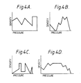
- FIGS 3A-3D illustrate by way of example four different colour selection functions which are associated with the cyan, magenta, yellow and black colour components respectively.
- Each look-up table has a set of addresses corresponding to all possible pressure values, typically 128, and in each address a density value is stored as defined by the appropriate function. It will be noted that in these examples each colour selection function is discontinuous (although this will not always be the case) and for each colour component there are certain pressure values which result in a zero density value. It will be noted, however, that the four functions are different.
- FIGS 4A-4D illustrate four further colour selection functions.
Abstract
Description
- The invention relates to image processing apparatus.
- In accordance with the present invention, image processing apparatus comprises an input device including an indicator and a surface over which the indicator is moved; position determining means for determining the position of the indicator on the surface; a force monitor for monitoring the force with which the indicator is pressed onto the surface; a frame store for storing digital data defining the colour component content of an image; and processing means connected to the input device and the frame store for simulating an electronic paint brush carrying paint which is laid down in the frame store at locations corresponding to the positions of the indicator on the surface and whose characteristics are determined at least in part in accordance with the force monitored by the force monitor.
- We have developed a new type of image processing apparatus which enables many interesting and unusual effects to be achieved in which the characteristics of the paint carried by the paint brush are determined at least in part by the force with which the indicator is pressed onto the surface. Examples of paint characteristics include hue, brightness and saturation. A particularly advantageous application involves modifying brightness and saturation while maintaining hue constant.
- The invention is applicable to modifying images which have been scanned using a conventional electronic scanner but is particularly applicable to images which are created electronically by use of the input device. The invention can be used to create an image in the frame store or to modify an existing image in which the new paint is combined with previous paint in a known manner.
- Preferably, the processing means applies to the monitored force value a colour selection function for each colour component, the colour selection function defining the variation in characteristic(s) of the corresponding colour component with monitored force.
- Preferably, the colour selection function is discontinuous and defines colour component values for spaced groups of force values. Thus, in this case, there will be certain force values for which a colour component value of zero is obtained.
- Other forms of the colour selection function are also possible so that for example the function can define a straight or curved variation or be non-uniform and can vary either in a controlled manner or in a random manner, for example separate Gaussian variations in each colour channel. That is each component could have a random offset added or subtracted from the current colour value, the probability of any particular offset being e.g. Gaussian. The pen pressure would be used to modulate the "width of the Gaussian curve, with hard pressure giving a higher probability of getting a given, large change from the "base" colour.
- Where the image is defined by more than one colour component, the associated colour selection functions are preferably different.
- The processing means defines, in a conventional manner, the shape, size and density profile of the brush.
- Typically, the indicator comprises a pressure pen and the surface is defined by a digitising tablet. Other forms of input device, however, are also possible.
- Preferably, the apparatus further comprises a display connected to the frame store so as to display the image defined by digital data in the frame store.
- The processing means may be provided by a suitably programmed computer or by hard wired circuits.
- An example of image processing apparatus according to the invention will now be described with reference to the accompanying drawings, in which:-
- Figure 1 is a block diagram of the apparatus;
- Figure 2 is a block diagram of the graphics image processor of Figure 1;
- Figures 3A-3D illustrate four different colour selection functions; and,
- Figures 4A-4D illustrate four further colour selection functions.
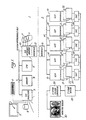
- The apparatus shown in Figure 1 can be divided into two primary parts. These comprise the host 1 and the
graphics sub-system 2. The division is shown in Figure 1 by a dashed line. The host 1 is a 68020 microprocessor based system running UNIX which is a multi-tasking, multi-user operating system. The host comprises an I/O processor 3 coupled to akeyboard 4, a digitizing tablet 5 and associated pen 31, a system disk 6 and other data sources (not shown). The I/O processor 3 is connected to a system inter-connect bus (SIB) 7 which is connected to ROM andRAM memory 8, a CPU 9, and aninterface adapter 10. Theinterface adapter 10 is connected to a number of high speed image discs 11 which hold data defining the colour content of pixels of images at high resolution, the adapter also being connected via aninterface 12 with thegraphics sub-system 2. As mentioned above, the host has a conventional form and will not be described in detail. However, the SIB 7 is described in more detail in EP-A-0332417. - The programme that runs on the host is a single "process" which reads and processes inputs from the digitizing tablet 5 under operator control and directs the
graphics part 2 to display the host's responses to those inputs on thegraphics monitor 30. Essentially, the system takes advantage of the host system in being able to perform a majority of the calculations so that only a small amount of control data is passed to the graphics sub-system. Thisgraphics part 2 is much better than the host 1 at creating and manipulating graphical objects but the host is better at controlling input/output to peripherals, discs and tapes and is relatively easy to programme. - The
graphics sub-system 2 comprises aninterface 13 which connects the graphics part to the host 1, theinterface 13 being connected to abus 14. Thebus 14 is connected to five graphics image processors (GIPs) 15-19. In this embodiment, it is assumed that the images are defined by four colour components, namely cyan, magenta, yellow and black, there being a separate GIP for each colour. Thus, theGIP 15 processes the cyan colour component, theGIP 16 the magenta colour component, theGIP 17 the yellow colour component and theGIP 18 the black colour component. If the image was represented by a different number of colour components, for example red, green and blue then only three of the GIPs would be needed. The advantage of providing the GIPs 15-18 in parallel is that each component of each pixel in the image can be processed in parallel so that the overall processing time is reduced by up to four times over the processing time with a single processor. A further advantage of using the GIPs is that each has a bit-slice processor on which the programmer can define instructions useful for a particular application. - A
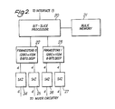
fifth GIP 19 is provided for defining one or more masks and other features. - The construction of one of the GIPs of Figure 1 is shown in Figure 2. Each GIP comprises a bit-
slice processor 20 coupled tobulk memory 21. Thismemory 21 will hold image data, brush profiles and text as required and is used as virtual image memory. - The bit-
slice processor 20 is also connected to a pair offramestores mask GIP 19 each framestore can be used to hold 8 bit masks or two separate 4 bit masks. Furthermore, one of the framestores in theGIP 19 can be used to display menus in one four bit plane and overlays in the other four bit plane. Overlays comprise construction lines and boxes and the like which are to be displayed on the monitor. - The eight bit data in each
framestore mixer circuit 28. Thecircuit 28 mixes the data from each of theframestores 22 associated with the GIPs 15-18 with the data from each of theframe stores 23 associated with the GIPs 15-18 in accordance with the mask stored in theframestore 22 of theGIP 19. This mixer circuit which operates in two stages is described in more detail in EP-A-0344976. - The output from the
mixer circuit 28 is fed to a twostage colour converter 29 which converts the four colour component data to three colour component data e.g. red, green and blue suitable for controlling the display on amonitor screen 30. - In use, images are stored on the high speed image disks 11 and these images may have been generated by scanning original transparencies or other representations or they may have been created electronically using an electronic paint brush. The host 1 causes relevant portions of these images to be "paged" in and out of the
bulk memory 21 in the GIPs 15-18 and brush profiles to be loaded and unloaded from thebulk memory 21 in theGIP 19. Theinterface adaptor 10 has its own 68020 processor to allow it independently to control the disks 11. The GIPs 15-18 are directed by the host 1 to do various things to images in thebulk memory 21 so that when a GIP attempts to access an address in an image that is not currently in its bulk memory then part of that memory is written back to disc and a new portion read in. After the GIPs have finished processing, the data in the framestores is then scrolled, zoomed and/or amplified as necessary, mixed in thecircuit 28, converted to monitor format and then displayed. - If the host 1 wishes to display menus on the screen, these are drawn into the
mask GIP framestore 23, known as the "overlay plane". - The digitising tablet 5 not only indicates the current location of the pen 31 but also the pressure with which the pen is applied to the tablet. This pressure is contained within a seven digit data field allowing 128 possible pressure levels. The pressure value is taken by the host 1 and is used to address respective look-up tables in the
memory 8. These look-up tables define the colour components of the colour to be used by the paint brush generated by the GIPs 15-18. - Figures 3A-3D illustrate by way of example four different colour selection functions which are associated with the cyan, magenta, yellow and black colour components respectively. Each look-up table has a set of addresses corresponding to all possible pressure values, typically 128, and in each address a density value is stored as defined by the appropriate function. It will be noted that in these examples each colour selection function is discontinuous (although this will not always be the case) and for each colour component there are certain pressure values which result in a zero density value. It will be noted, however, that the four functions are different.
- Figures 4A-4D illustrate four further colour selection functions.
- In operation, the operator or artist moves the pressure pen 31 across the tablet 5 and the host 1 monitors the applied pressure. The pressure signal is sampled regularly and in response to each pressure sample the look-up tables are addressed and the appropriate colour component values accessed. These values are then used after modification by the density profile of the selected "brush", to lay down paint in the frame stores 23. The result is displayed on the
monitor 30 after combination with any image in the frame stores 22. - The invention can have the effect of working with a multi-layer scraper board, given suitable look-up functions. That is, it gives the appearance that the harder the applied pressure the more layers are scraped away to reveal a particular colour. If the brush has a curved density profile then the colours which have been scraped away would still remain visible at the edges of the brush so that the artist can soon learn to pass from a doodling mode in which colours flow rather like a oil film on water, to a controlled artistic mode in which selected colours can be pushed in a chosen direction.
- In one application, the host 1 could respond to the detection of two different pressures at spaced positions across the tablet 5 to generate automatically a linear vignette of colour varying between the colours defined by the two pressures.
Claims (7)
- Image processing apparatus comprising an input device including an indicator (31) and a surface (5) over which the indicator is moved; position determining means for determining the position of the indicator on the surface; a force monitor (3) for monitoring the force with which the indicator is pressed onto the surface; a frame store (22) for storing digital data defining the colour component content of an image; and processing means (3) connected to the input device and the frame store for simulating an electronic paint brush carrying paint which is laid down in the frame store at locations corresponding to the positions of the indicator on the surface and whose characteristics are determined at least in part in accordance with the force monitored by the force monitor.
- Apparatus according to claim 1, wherein the characteristics are chosen from hue, brightness and saturation.
- Apparatus according to claim 2, wherein the processing means is adapted to maintain hue constant while modifying brightness and saturation in accordance with the monitored force.
- Apparatus according to any of the preceding claims, wherein the processing means applies to the monitored force value a colour selection function for each colour component, the colour selection function defining the variation in characteristic(s) of the corresponding colour component with monitored force.
- Apparatus according to claim 4, wherein the colour selection function is discontinuous and defines colour component values for spaced groups of force values.
- Apparatus according to claim 4 or claim 5, wherein the image is defined by more than one colour component, the associated colour selection functions being different.
- Apparatus according to any of the preceding claims, further comprising a display (30) connected to the frame store (22) so as to display the image defined by digital data in the frame store.
Applications Claiming Priority (2)
| Application Number | Priority Date | Filing Date | Title |
|---|---|---|---|
| GB9008946 | 1990-04-20 | ||
| GB909008946A GB9008946D0 (en) | 1990-04-20 | 1990-04-20 | Image processing apparatus |
Publications (2)
| Publication Number | Publication Date |
|---|---|
| EP0453243A2 true EP0453243A2 (en) | 1991-10-23 |
| EP0453243A3 EP0453243A3 (en) | 1992-10-14 |
Family
ID=10674758
Family Applications (1)
| Application Number | Title | Priority Date | Filing Date |
|---|---|---|---|
| EP19910303389 Withdrawn EP0453243A3 (en) | 1990-04-20 | 1991-04-17 | Image processing apparatus |
Country Status (4)
| Country | Link |
|---|---|
| US (1) | US5343220A (en) |
| EP (1) | EP0453243A3 (en) |
| JP (1) | JPH04227521A (en) |
| GB (1) | GB9008946D0 (en) |
Cited By (6)
| Publication number | Priority date | Publication date | Assignee | Title |
|---|---|---|---|---|
| WO1993016431A1 (en) * | 1992-02-11 | 1993-08-19 | Altsys Corporation | System and method of generating variable width lines |
| EP0576846A1 (en) * | 1992-06-02 | 1994-01-05 | Fuji Xerox Co., Ltd. | Document processing system |
| EP0595746A1 (en) * | 1992-10-29 | 1994-05-04 | International Business Machines Corporation | Method and system for input device pressure indication in a data processing system |
| US6441156B1 (en) | 1998-12-30 | 2002-08-27 | The United States Of America As Represented By The Department Of Health And Human Services | Calcium channel compositions and methods of use thereof |
| US6875606B1 (en) | 1997-10-23 | 2005-04-05 | The United States Of America As Represented By The Department Of Veterans Affairs | Human α-7 nicotinic receptor promoter |
| US8274361B2 (en) | 2006-01-25 | 2012-09-25 | Koninklijke Philips Electronics N.V. | Control device for selecting the color of light emitted by a light source |
Families Citing this family (24)
| Publication number | Priority date | Publication date | Assignee | Title |
|---|---|---|---|---|
| US5592597A (en) * | 1994-02-14 | 1997-01-07 | Parametric Technology Corporation | Real-time image generation system for simulating physical paint, drawing media, and feature modeling with 3-D graphics |
| CN1171161A (en) * | 1994-11-03 | 1998-01-21 | 参数技术有限公司 | Computer system for reconstructing 3D object using transformations between screen and model space |
| AU4985096A (en) * | 1995-03-02 | 1996-09-18 | Parametric Technology Corporation | Computer graphics system for creating and enhancing texture maps |
| JP3705455B2 (en) * | 1996-04-12 | 2005-10-12 | Smk株式会社 | Resistive pressure-sensitive coordinate input device |
| US5790114A (en) * | 1996-10-04 | 1998-08-04 | Microtouch Systems, Inc. | Electronic whiteboard with multi-functional user interface |
| US6320592B1 (en) * | 1997-06-30 | 2001-11-20 | Sun Microsystems, Inc. | Method and apparatus for separating image data from a color system in image processing |
| US6801211B2 (en) | 2001-12-21 | 2004-10-05 | Ladd B. Forsline | Computer painting system with passive paint brush stylus |
| US7423696B2 (en) * | 2005-01-07 | 2008-09-09 | Hewlett-Packard Development Company, L.P. | Concurrent luminance-saturation adjustment of digital images |
| US7734114B1 (en) * | 2005-12-07 | 2010-06-08 | Marvell International Ltd. | Intelligent saturation of video data |
| US20090277470A1 (en) * | 2008-05-08 | 2009-11-12 | Mitchell Monique M | Artificial nail decorating system utilizing computer technology |
| US8760438B2 (en) * | 2010-05-28 | 2014-06-24 | Adobe Systems Incorporated | System and method for simulating stiff bristle brushes using stiffness-height parameterization |
| US9493342B2 (en) | 2012-06-21 | 2016-11-15 | Nextinput, Inc. | Wafer level MEMS force dies |
| EP2870445A1 (en) | 2012-07-05 | 2015-05-13 | Ian Campbell | Microelectromechanical load sensor and methods of manufacturing the same |
| WO2015106246A1 (en) | 2014-01-13 | 2015-07-16 | Nextinput, Inc. | Miniaturized and ruggedized wafer level mems force sensors |
| CN117486166A (en) | 2015-06-10 | 2024-02-02 | 触控解决方案股份有限公司 | Reinforced wafer level MEMS force sensor with tolerance trenches |
| CN116907693A (en) | 2017-02-09 | 2023-10-20 | 触控解决方案股份有限公司 | Integrated digital force sensor and related manufacturing method |
| US11243125B2 (en) | 2017-02-09 | 2022-02-08 | Nextinput, Inc. | Integrated piezoresistive and piezoelectric fusion force sensor |
| US11221263B2 (en) | 2017-07-19 | 2022-01-11 | Nextinput, Inc. | Microelectromechanical force sensor having a strain transfer layer arranged on the sensor die |
| US11423686B2 (en) | 2017-07-25 | 2022-08-23 | Qorvo Us, Inc. | Integrated fingerprint and force sensor |
| US11243126B2 (en) | 2017-07-27 | 2022-02-08 | Nextinput, Inc. | Wafer bonded piezoresistive and piezoelectric force sensor and related methods of manufacture |
| WO2019079420A1 (en) | 2017-10-17 | 2019-04-25 | Nextinput, Inc. | Temperature coefficient of offset compensation for force sensor and strain gauge |
| US11385108B2 (en) | 2017-11-02 | 2022-07-12 | Nextinput, Inc. | Sealed force sensor with etch stop layer |
| WO2019099821A1 (en) | 2017-11-16 | 2019-05-23 | Nextinput, Inc. | Force attenuator for force sensor |
| US10962427B2 (en) | 2019-01-10 | 2021-03-30 | Nextinput, Inc. | Slotted MEMS force sensor |
Citations (2)
| Publication number | Priority date | Publication date | Assignee | Title |
|---|---|---|---|---|
| GB2116407A (en) * | 1982-03-11 | 1983-09-21 | Quantel Ltd | Electonically synthesised video palette |
| GB2238214A (en) * | 1989-10-13 | 1991-05-22 | Quantel Ltd | Electronic graphic system combines images using variable density stencil |
Family Cites Families (7)
| Publication number | Priority date | Publication date | Assignee | Title |
|---|---|---|---|---|
| US4200867A (en) * | 1978-04-03 | 1980-04-29 | Hill Elmer D | System and method for painting images by synthetic color signal generation and control |
| ATE45639T1 (en) * | 1981-04-10 | 1989-09-15 | Ampex | CONTROL FOR AN IMAGE SPATIAL TRANSFORMATION DEVICE. |
| DE3364249D1 (en) * | 1982-03-30 | 1986-07-31 | Crosfield Electronics Ltd | Video retouching systems |
| US4829455A (en) * | 1986-04-11 | 1989-05-09 | Quantel Limited | Graphics system for video and printed images |
| GB8805668D0 (en) * | 1988-03-10 | 1988-04-07 | Crosfield Electronics Ltd | Image data handling |
| GB8812891D0 (en) * | 1988-05-31 | 1988-07-06 | Crosfield Electronics Ltd | Image generating apparatus |
| US5142273A (en) * | 1990-09-20 | 1992-08-25 | Ampex Corporation | System for generating color blended video signal |
-
1990
- 1990-04-20 GB GB909008946A patent/GB9008946D0/en active Pending
-
1991
- 1991-04-17 EP EP19910303389 patent/EP0453243A3/en not_active Withdrawn
- 1991-04-19 JP JP3088728A patent/JPH04227521A/en active Pending
-
1993
- 1993-03-16 US US08/031,915 patent/US5343220A/en not_active Expired - Fee Related
Patent Citations (2)
| Publication number | Priority date | Publication date | Assignee | Title |
|---|---|---|---|---|
| GB2116407A (en) * | 1982-03-11 | 1983-09-21 | Quantel Ltd | Electonically synthesised video palette |
| GB2238214A (en) * | 1989-10-13 | 1991-05-22 | Quantel Ltd | Electronic graphic system combines images using variable density stencil |
Non-Patent Citations (1)
| Title |
|---|
| IMAGE TECHNOLOGY (JOURNAL OF THE BKSTS). vol. 68, no. 8, August 1986, LONDON GB pages 392 - 394; R. VAN DER LEEDEN: 'AMPEX AVA-3 VIDEO ART SYSTEM' * |
Cited By (9)
| Publication number | Priority date | Publication date | Assignee | Title |
|---|---|---|---|---|
| WO1993016431A1 (en) * | 1992-02-11 | 1993-08-19 | Altsys Corporation | System and method of generating variable width lines |
| EP0576846A1 (en) * | 1992-06-02 | 1994-01-05 | Fuji Xerox Co., Ltd. | Document processing system |
| US5671429A (en) * | 1992-06-02 | 1997-09-23 | Fuji Xerox Co., Ltd. | Document processing system providing facilitated modification of document images |
| EP0595746A1 (en) * | 1992-10-29 | 1994-05-04 | International Business Machines Corporation | Method and system for input device pressure indication in a data processing system |
| US6875606B1 (en) | 1997-10-23 | 2005-04-05 | The United States Of America As Represented By The Department Of Veterans Affairs | Human α-7 nicotinic receptor promoter |
| US7572580B2 (en) | 1997-10-23 | 2009-08-11 | The United States Of America As Represented By The Department Of Veterans Affairs | Promoter variants of the alpha-7 nicotinic acetylcholine receptor |
| US6441156B1 (en) | 1998-12-30 | 2002-08-27 | The United States Of America As Represented By The Department Of Health And Human Services | Calcium channel compositions and methods of use thereof |
| US6979724B2 (en) | 1998-12-30 | 2005-12-27 | The United States Of America As Represented By The Secretary Of The Department Of Health And Human Services | Calcium channel proteins |
| US8274361B2 (en) | 2006-01-25 | 2012-09-25 | Koninklijke Philips Electronics N.V. | Control device for selecting the color of light emitted by a light source |
Also Published As
| Publication number | Publication date |
|---|---|
| GB9008946D0 (en) | 1990-06-20 |
| US5343220A (en) | 1994-08-30 |
| EP0453243A3 (en) | 1992-10-14 |
| JPH04227521A (en) | 1992-08-17 |
Similar Documents
| Publication | Publication Date | Title |
|---|---|---|
| US5343220A (en) | Force monitor of an electronic paint brush apparatus | |
| US5473740A (en) | Method and apparatus for interactively indicating image boundaries in digital image cropping | |
| US5289168A (en) | Image handling apparatus and controller for selecting display mode | |
| US6226010B1 (en) | Color selection tool | |
| JPH0473189B2 (en) | ||
| GB2233856A (en) | Electronic image processing | |
| US5325471A (en) | Method of and apparatus for modifying image by adjusting modification coefficients | |
| US6002408A (en) | Blend control system | |
| US5227770A (en) | Electronic boundary generation | |
| EP0441499B1 (en) | Electronic brush generation | |
| US5335318A (en) | Electronic image generation apparatus including a camera for recording a region and producing a control data array | |
| US5185596A (en) | Electronic image modification | |
| US5311333A (en) | Image processing apparatus | |
| GB2267633A (en) | Analyzing image data processing operations | |
| US6211885B1 (en) | Apparatus for outputting an image in which data of points on texture pattern are mapped to data of dots on display plane | |
| EP0404397B1 (en) | Image processing system | |
| EP0441497B1 (en) | Electronic image processing system | |
| WO1991012587A1 (en) | Graphics system | |
| EP0439332B1 (en) | Electronic image creation tools | |
| EP0441498A2 (en) | Generating control data array | |
| Takakura et al. | Production of artistic images with “ART PROCESSOR” | |
| JPH0567210A (en) | Picture area detection device | |
| Nusse et al. | Screen Utilities | |
| JPH04316091A (en) | Circuit for generating picture-element value as threshold value for overlay | |
| JPH0679337B2 (en) | Image processing method |
Legal Events
| Date | Code | Title | Description |
|---|---|---|---|
| PUAI | Public reference made under article 153(3) epc to a published international application that has entered the european phase |
Free format text: ORIGINAL CODE: 0009012 |
|
| AK | Designated contracting states |
Kind code of ref document: A2 Designated state(s): DE GB |
|
| RAP1 | Party data changed (applicant data changed or rights of an application transferred) |
Owner name: CROSFIELD ELECTRONICS LIMITED |
|
| PUAL | Search report despatched |
Free format text: ORIGINAL CODE: 0009013 |
|
| AK | Designated contracting states |
Kind code of ref document: A3 Designated state(s): DE GB |
|
| 17P | Request for examination filed |
Effective date: 19930416 |
|
| STAA | Information on the status of an ep patent application or granted ep patent |
Free format text: STATUS: THE APPLICATION HAS BEEN WITHDRAWN |
|
| 18W | Application withdrawn |
Withdrawal date: 19950406 |