EP0453076B1 - Plasma blasting method - Google Patents
Plasma blasting method Download PDFInfo
- Publication number
- EP0453076B1 EP0453076B1 EP91301810A EP91301810A EP0453076B1 EP 0453076 B1 EP0453076 B1 EP 0453076B1 EP 91301810 A EP91301810 A EP 91301810A EP 91301810 A EP91301810 A EP 91301810A EP 0453076 B1 EP0453076 B1 EP 0453076B1
- Authority
- EP
- European Patent Office
- Prior art keywords
- electrolyte
- substance
- confined area
- plasma
- energy
- Prior art date
- Legal status (The legal status is an assumption and is not a legal conclusion. Google has not performed a legal analysis and makes no representation as to the accuracy of the status listed.)
- Expired - Lifetime
Links
Images
Classifications
-
- E—FIXED CONSTRUCTIONS
- E21—EARTH OR ROCK DRILLING; MINING
- E21C—MINING OR QUARRYING
- E21C37/00—Other methods or devices for dislodging with or without loading
- E21C37/18—Other methods or devices for dislodging with or without loading by electricity
-
- E—FIXED CONSTRUCTIONS
- E21—EARTH OR ROCK DRILLING; MINING
- E21B—EARTH OR ROCK DRILLING; OBTAINING OIL, GAS, WATER, SOLUBLE OR MELTABLE MATERIALS OR A SLURRY OF MINERALS FROM WELLS
- E21B7/00—Special methods or apparatus for drilling
- E21B7/14—Drilling by use of heat, e.g. flame drilling
- E21B7/15—Drilling by use of heat, e.g. flame drilling of electrically generated heat
Definitions
- This invention relates to a plasma blasting process for fragmenting a substance such as rock and more particularly for hard rock mining.
- the traditional method of hard rock mining is a batch process with the following sequence: Holes are drilled in the rock, chemical explosives placed into the holes, and the mine personnel evacuated; then the explosives are detonated, causing a quantity of rock to be separated from the solid rock mass; gases generated by the explosives are then ventilated out before the miners can return.
- US-A-3,158,207 provides a spark discharge drill operating on this principle.
- US-A-3,364,708 gives a good overall review of this phenomenon.
- US-A-3,500,942; US-A-3,583,766 and US-A-3,679,007 relate to drills in which an electric discharge takes place between two electrodes immersed in a fluid such as water, thereby producing a high temperature, high pressure plasma between the electrodes. The expansion of the plasma produces a strong pressure or shock wave which enhances the drilling effect.
- the main disadvantages of electrohydraulic fracturing are that the pressure pulse is spread out and a large fraction of energy is dissipated in the water (see B.K. Parekh, et al., Supra).
- Applicant has now surprisingly found that by delivering electrical energy at at least 100, preferably in excess of 200 megawatts per microsecond until a peak power of at least 3, preferably in excess of 4 gigawatts is reached across the gap of two poles of a coaxial electrode assembly immersed in an electrolyte within a confined area of a substance to be blasted, one can produce a dielectric breakdown of the electrolyte resulting in the formation of plasma within such confined area which creates a pressure sufficient to blast such substance in the manner of a high explosive charge.
- the electrolyte could be water or a solution suitable for dielectric breakdown.
- a preferred solution is that of copper sulphate.
- the electrolyte may also be combined with a gelling agent such as bentonite or gelatin in order to make it viscous enough so that it would not run out of the confined area prior to blasting.
- a gelling agent such as bentonite or gelatin
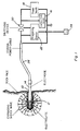
- the plasma blasting method in accordance with the present invention requires drilling of a hole 10 into the rock face by conventional drilling.
- a small amount of viscous electrolyte 12 such as copper sulphate, is injected into the hole and a coaxial blasting electrode 14 is inserted in the hole.
- Electrical energy typically 300-1000 kilojoules, is delivered into approximately 20-50 grams of the electrolyte under confinement within the hole.
- Typical dimensions for the hole are about 50 mm diameter and 500 mm depth. These dimensions may change depending on the size of the blasting electrode and the amount of energy input.
- the diameter of the hole should be such that the blasting electrode would have a close fit and the greater the energy input the deeper the hole would be.
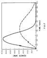
- the blasting electrode which fits closely into the hole serves two purposes: (1) it carries electrical energy to the electrolyte, (2) it produces the required confinement for the blast by plugging up the hole. Rapid delivery of the electrical energy is important for the development of the desired high peak pressure. Energy is delivered at at least 100 and preferably in excess of 200 megawatts per microsecond until a peak power of at least 3 gigawatts and preferably in excess of 4 gigawatts is reached as illustrated in Figure 2 of the drawings. The peak pressure developed has been found to be in excess of 1 gigapascal, or 10,000 atmospheres which is sufficient to blast hard rock in the manner of a high explosive charge.
- Applicant has found that if the energy is delivered at less than 100 megawatts per microsecond such as illustrated, for example, by the dotted line in Figure 2, or the peak power is substantially less than 3 gigawatts, insufficient pressure is created to adequately blast the rock, although the amount of energy delivered (area under the curves) is essentially the same.
- the electrical energy required for the blast is conveniently stored in a capacitor bank 16 which is electrically charged by a suitable D.C. power supply 18.
- the switch is triggered by a triggering device 22 which is initiated by a remote trigger 24 through a fiber optic cable or a pneumatic tube to provide perfect electrical isolation for the operator.
- the capacitor bank is connected to the blasting electrode through an electrical circuit including a coaxial power cable 26 which is designed for minimum inductance and resistance to reduce power losses and ensure rapid discharge of energy (at the above disclosed rate) into the rock for the development of an intense shockwave.
- the electrode Prior to the blast, the electrode is maintained at ground potential but when the switch is triggered the center lead of the coaxial electrode is raised to the high voltage of the capacitor bank.
- the electrolyte in the hole then suffers a dielectric breakdown producing a plasma at extremely high temperature and pressure. In this manner, a great amount of energy is transferred within a very short time from the capacitor bank into the small amount of electrolyte in the confined area around the electrode thereby instantaneously transforming this entire finite amount of electrolyte into plasma which must then release this energy by way of a pressure wave, thus resulting in a blast similar to that made by dynamite or other chemical explosives.
- the plasma electrode may be equipped with a recoil mechanism to damp out the destructive effect of the blast on the electrode.
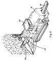
- Figure 3 is a diagram of a continuous mining and tunneling machine 30 at the back of which is mounted the capacitor bank and associated equipment 32 for triggering a blasting electrode mounted on one or several booms 34 located at the front of the machine.
- a drilling and blasting head 36 is provided at the end of the boom. The rock blasted from the mine face is collected at the front of the machine onto a conveyor 38 extending to the back of the machine for loading into conventional transport equipment.
Landscapes
- Engineering & Computer Science (AREA)
- Mining & Mineral Resources (AREA)
- Life Sciences & Earth Sciences (AREA)
- Geology (AREA)
- General Life Sciences & Earth Sciences (AREA)
- Geochemistry & Mineralogy (AREA)
- Fluid Mechanics (AREA)
- Environmental & Geological Engineering (AREA)
- Physics & Mathematics (AREA)
- Drilling And Exploitation, And Mining Machines And Methods (AREA)
- Coating By Spraying Or Casting (AREA)
- Disintegrating Or Milling (AREA)
- Polysaccharides And Polysaccharide Derivatives (AREA)
- Devices For Conveying Motion By Means Of Endless Flexible Members (AREA)
- Electrical Discharge Machining, Electrochemical Machining, And Combined Machining (AREA)
- Application Of Or Painting With Fluid Materials (AREA)
- Physical Or Chemical Processes And Apparatus (AREA)
Applications Claiming Priority (2)
| Application Number | Priority Date | Filing Date | Title |
|---|---|---|---|
| CA002015102A CA2015102C (en) | 1990-04-20 | 1990-04-20 | Plasma blasting method |
| CA2015102 | 1990-04-20 |
Publications (2)
| Publication Number | Publication Date |
|---|---|
| EP0453076A1 EP0453076A1 (en) | 1991-10-23 |
| EP0453076B1 true EP0453076B1 (en) | 1995-06-07 |
Family
ID=4144792
Family Applications (1)
| Application Number | Title | Priority Date | Filing Date |
|---|---|---|---|
| EP91301810A Expired - Lifetime EP0453076B1 (en) | 1990-04-20 | 1991-03-05 | Plasma blasting method |
Country Status (6)
| Country | Link |
|---|---|
| EP (1) | EP0453076B1 (fi) |
| AT (1) | ATE123554T1 (fi) |
| AU (1) | AU627984B2 (fi) |
| CA (1) | CA2015102C (fi) |
| DE (1) | DE69110186T2 (fi) |
| FI (1) | FI911900L (fi) |
Families Citing this family (9)
| Publication number | Priority date | Publication date | Assignee | Title |
|---|---|---|---|---|
| AU656818B2 (en) * | 1992-11-05 | 1995-02-16 | Assa Abloy Australia Pty Limited | Improvement to deadlocks |
| CA2262581C (en) * | 1996-08-05 | 2006-01-03 | Tetra Corporation | Electrohydraulic pressure wave projectors |
| DE69810347D1 (de) * | 1997-11-06 | 2003-01-30 | Boskalis Bv Baggermaatschappij | Verfahren und vorrichtung zum zerkleinern von gestein |
| KR100308081B1 (ko) | 1999-03-02 | 2001-09-24 | 정기형 | 플라즈마파암용 전력충격쎌 |
| RU2228436C2 (ru) * | 2002-04-23 | 2004-05-10 | Открытое акционерное общество "Инфотэк Груп" | Способ получения высоких температур и давлений в ограниченном и замкнутом пространстве |
| US10060195B2 (en) | 2006-06-29 | 2018-08-28 | Sdg Llc | Repetitive pulsed electric discharge apparatuses and methods of use |
| US8628146B2 (en) * | 2010-03-17 | 2014-01-14 | Auburn University | Method of and apparatus for plasma blasting |
| US10407995B2 (en) | 2012-07-05 | 2019-09-10 | Sdg Llc | Repetitive pulsed electric discharge drills including downhole formation evaluation |
| BR112016006434B1 (pt) | 2013-09-23 | 2022-02-15 | Sdg, Llc | Método para fornecer um pulso de alta tensão a uma broca de perfuração eletrotrituradora ou eletrohidráulica, e, equipamento para chavear potência para uso em perfuração eletrotrituradora ou eletro-hidráulica |
Family Cites Families (3)
| Publication number | Priority date | Publication date | Assignee | Title |
|---|---|---|---|---|
| US3158207A (en) * | 1961-08-14 | 1964-11-24 | Jersey Producttion Res Company | Combination roller cone and spark discharge drill bit |
| US3583766A (en) * | 1969-05-22 | 1971-06-08 | Louis R Padberg Jr | Apparatus for facilitating the extraction of minerals from the ocean floor |
| US3679007A (en) * | 1970-05-25 | 1972-07-25 | Louis Richard O Hare | Shock plasma earth drill |
-
1990
- 1990-04-20 CA CA002015102A patent/CA2015102C/en not_active Expired - Fee Related
-
1991
- 1991-02-04 AU AU70208/91A patent/AU627984B2/en not_active Ceased
- 1991-03-05 EP EP91301810A patent/EP0453076B1/en not_active Expired - Lifetime
- 1991-03-05 DE DE69110186T patent/DE69110186T2/de not_active Expired - Fee Related
- 1991-03-05 AT AT91301810T patent/ATE123554T1/de not_active IP Right Cessation
- 1991-04-19 FI FI911900A patent/FI911900L/fi unknown
Also Published As
| Publication number | Publication date |
|---|---|
| ATE123554T1 (de) | 1995-06-15 |
| AU627984B2 (en) | 1992-09-03 |
| CA2015102A1 (en) | 1991-10-20 |
| FI911900A7 (fi) | 1991-10-21 |
| DE69110186T2 (de) | 1995-12-14 |
| FI911900L (fi) | 1991-10-21 |
| CA2015102C (en) | 1995-09-19 |
| DE69110186D1 (de) | 1995-07-13 |
| EP0453076A1 (en) | 1991-10-23 |
| AU7020891A (en) | 1991-10-24 |
| FI911900A0 (fi) | 1991-04-19 |
Similar Documents
| Publication | Publication Date | Title |
|---|---|---|
| US5106164A (en) | Plasma blasting method | |
| JP2960550B2 (ja) | 硬岩を爆破する方法および装置 | |
| US7527108B2 (en) | Portable electrocrushing drill | |
| CA2658570C (en) | Portable and directional electrocrushing drill | |
| US5896938A (en) | Portable electrohydraulic mining drill | |
| US8567522B2 (en) | Apparatus and method for supplying electrical power to an electrocrushing drill | |
| CA2581701C (en) | Pulsed electric rock drilling, fracturing, and crushing methods and apparatus | |
| EP0453076B1 (en) | Plasma blasting method | |
| CN108267053A (zh) | 一种利用液电效应产生等离子体爆破岩石的机械装置 | |
| CN219262282U (zh) | 钻具、工作系统及作业机械 | |
| AU2013204846B2 (en) | Pulsed Electric Rock Drilling, Fracturing, and Crushing Methods and Apparatus | |
| CA2220920C (en) | Method and apparatus for blasting hard rock | |
| CA2844571C (en) | Portable electrocrushing drill | |
| KR20250010853A (ko) | 파암용 와이어 카트리지 및 이를 이용한 펄스 파워 파암 시스템 | |
| Brown et al. | Rock fragmentation | |
| CN111894620A (zh) | 一种高压电辅助破岩巷道掘进施工方法 |
Legal Events
| Date | Code | Title | Description |
|---|---|---|---|
| PUAI | Public reference made under article 153(3) epc to a published international application that has entered the european phase |
Free format text: ORIGINAL CODE: 0009012 |
|
| AK | Designated contracting states |
Kind code of ref document: A1 Designated state(s): AT CH DE FR GB IT LI SE |
|
| 17P | Request for examination filed |
Effective date: 19911129 |
|
| 17Q | First examination report despatched |
Effective date: 19930303 |
|
| GRAA | (expected) grant |
Free format text: ORIGINAL CODE: 0009210 |
|
| AK | Designated contracting states |
Kind code of ref document: B1 Designated state(s): AT CH DE FR GB IT LI SE |
|
| REF | Corresponds to: |
Ref document number: 123554 Country of ref document: AT Date of ref document: 19950615 Kind code of ref document: T |
|
| REF | Corresponds to: |
Ref document number: 69110186 Country of ref document: DE Date of ref document: 19950713 |
|
| ITF | It: translation for a ep patent filed | ||
| ET | Fr: translation filed | ||
| PLBE | No opposition filed within time limit |
Free format text: ORIGINAL CODE: 0009261 |
|
| STAA | Information on the status of an ep patent application or granted ep patent |
Free format text: STATUS: NO OPPOSITION FILED WITHIN TIME LIMIT |
|
| 26N | No opposition filed | ||
| PGFP | Annual fee paid to national office [announced via postgrant information from national office to epo] |
Ref country code: AT Payment date: 20000216 Year of fee payment: 10 |
|
| PGFP | Annual fee paid to national office [announced via postgrant information from national office to epo] |
Ref country code: SE Payment date: 20000228 Year of fee payment: 10 |
|
| PGFP | Annual fee paid to national office [announced via postgrant information from national office to epo] |
Ref country code: CH Payment date: 20000229 Year of fee payment: 10 |
|
| PGFP | Annual fee paid to national office [announced via postgrant information from national office to epo] |
Ref country code: GB Payment date: 20000303 Year of fee payment: 10 |
|
| PGFP | Annual fee paid to national office [announced via postgrant information from national office to epo] |
Ref country code: FR Payment date: 20000331 Year of fee payment: 10 |
|
| PGFP | Annual fee paid to national office [announced via postgrant information from national office to epo] |
Ref country code: DE Payment date: 20000530 Year of fee payment: 10 |
|
| PG25 | Lapsed in a contracting state [announced via postgrant information from national office to epo] |
Ref country code: GB Free format text: LAPSE BECAUSE OF NON-PAYMENT OF DUE FEES Effective date: 20010305 Ref country code: AT Free format text: LAPSE BECAUSE OF NON-PAYMENT OF DUE FEES Effective date: 20010305 |
|
| PG25 | Lapsed in a contracting state [announced via postgrant information from national office to epo] |
Ref country code: SE Free format text: LAPSE BECAUSE OF NON-PAYMENT OF DUE FEES Effective date: 20010306 |
|
| PG25 | Lapsed in a contracting state [announced via postgrant information from national office to epo] |
Ref country code: LI Free format text: LAPSE BECAUSE OF NON-PAYMENT OF DUE FEES Effective date: 20010331 Ref country code: CH Free format text: LAPSE BECAUSE OF NON-PAYMENT OF DUE FEES Effective date: 20010331 |
|
| GBPC | Gb: european patent ceased through non-payment of renewal fee |
Effective date: 20010305 |
|
| EUG | Se: european patent has lapsed |
Ref document number: 91301810.7 |
|
| REG | Reference to a national code |
Ref country code: CH Ref legal event code: PL |
|
| PG25 | Lapsed in a contracting state [announced via postgrant information from national office to epo] |
Ref country code: FR Free format text: LAPSE BECAUSE OF NON-PAYMENT OF DUE FEES Effective date: 20011130 |
|
| REG | Reference to a national code |
Ref country code: FR Ref legal event code: ST |
|
| PG25 | Lapsed in a contracting state [announced via postgrant information from national office to epo] |
Ref country code: DE Free format text: LAPSE BECAUSE OF NON-PAYMENT OF DUE FEES Effective date: 20020101 |
|
| PG25 | Lapsed in a contracting state [announced via postgrant information from national office to epo] |
Ref country code: IT Free format text: LAPSE BECAUSE OF NON-PAYMENT OF DUE FEES Effective date: 20050305 |