EP0453000A2 - Procédé pour le craquage catalytique fluidisé en deux phases - Google Patents
Procédé pour le craquage catalytique fluidisé en deux phases Download PDFInfo
- Publication number
- EP0453000A2 EP0453000A2 EP91111632A EP91111632A EP0453000A2 EP 0453000 A2 EP0453000 A2 EP 0453000A2 EP 91111632 A EP91111632 A EP 91111632A EP 91111632 A EP91111632 A EP 91111632A EP 0453000 A2 EP0453000 A2 EP 0453000A2
- Authority
- EP
- European Patent Office
- Prior art keywords
- catalyst
- additive
- cylinder
- particles
- riser
- Prior art date
- Legal status (The legal status is an assumption and is not a legal conclusion. Google has not performed a legal analysis and makes no representation as to the accuracy of the status listed.)
- Withdrawn
Links
Images


Classifications
-
- B—PERFORMING OPERATIONS; TRANSPORTING
- B01—PHYSICAL OR CHEMICAL PROCESSES OR APPARATUS IN GENERAL
- B01J—CHEMICAL OR PHYSICAL PROCESSES, e.g. CATALYSIS OR COLLOID CHEMISTRY; THEIR RELEVANT APPARATUS
- B01J8/00—Chemical or physical processes in general, conducted in the presence of fluids and solid particles; Apparatus for such processes
- B01J8/08—Chemical or physical processes in general, conducted in the presence of fluids and solid particles; Apparatus for such processes with moving particles
- B01J8/12—Chemical or physical processes in general, conducted in the presence of fluids and solid particles; Apparatus for such processes with moving particles moved by gravity in a downward flow
-
- C—CHEMISTRY; METALLURGY
- C10—PETROLEUM, GAS OR COKE INDUSTRIES; TECHNICAL GASES CONTAINING CARBON MONOXIDE; FUELS; LUBRICANTS; PEAT
- C10G—CRACKING HYDROCARBON OILS; PRODUCTION OF LIQUID HYDROCARBON MIXTURES, e.g. BY DESTRUCTIVE HYDROGENATION, OLIGOMERISATION, POLYMERISATION; RECOVERY OF HYDROCARBON OILS FROM OIL-SHALE, OIL-SAND, OR GASES; REFINING MIXTURES MAINLY CONSISTING OF HYDROCARBONS; REFORMING OF NAPHTHA; MINERAL WAXES
- C10G11/00—Catalytic cracking, in the absence of hydrogen, of hydrocarbon oils
- C10G11/14—Catalytic cracking, in the absence of hydrogen, of hydrocarbon oils with preheated moving solid catalysts
- C10G11/18—Catalytic cracking, in the absence of hydrogen, of hydrocarbon oils with preheated moving solid catalysts according to the "fluidised-bed" technique
- C10G11/182—Regeneration
Definitions
- This invention relates to a process and apparatus for fluid catalytic cracking a hydrocarbon feed using a mixture of two different kinds of cracking catalyst particles.
- a hydrocarbon feedstock such as gas oil
- Known catalysts include large pore crystalline zeolites, such as zeolite X or Y, and intermediate pore crystalline zeolites, such as ZSM-5.
- the reaction products with spent catalysts are discharged into a separator located in an enclosed stripping vessel, with the spent catalyst flowing downwardly therein. Entrained hydrocarbons are stripped from spent catalyst with stripping gas, such as steam or nitrogen.
- stripping gas such as steam or nitrogen.
- the stripped catalyst is then regenerated in a fluidized bed regenerator. Following regeneration, the catalyst is recycled to the riser to crack more feed.
- FCC processes are described in U. S. 3,617,497 and 4,219,407.
- ZSM-5 additive Another approach to keeping the ZSM-5 additive out of the regenerator is to make it very light, so that it can be collected in secondary cyclones downstream of the riser reactor.
- the use of ZSM-5 additive with very small particle size and catalyst recycle from secondary cyclones will work but will result in rapid loss of ZSM-5 additive with catalyst fines.
- Use of light, or low density, ZSM-5 additive will minimize the residence time of the ZSM-5 in the riser reactor because the light additive catalyst will not "slip" in the riser as much as the conventional catalyst.
- the light ZSM-5 will be largely kept out of the regenerator, but at the price of less residence time in the riser reactor.
- U. S. 4,336,160 reduces hydrothermal degradation by staged regeneration. However, all the catalyst from the reactor still is regenerated, thus providing opportunity for hydrothermal degradation.
- Separation of catalyst in the regenerator helps, but still exposes the additive to unnecessary regeneration.
- Use of a light-weight (or small size) additive can minimize additive residence time in the regenerator, but also minimizes additive residence time in the riser reactor.
- the present invention provides an apparatus for separating more elutriatable particles from less elutriatable particles, characterized by a vessel comprising sidewalls, a top portion and a bottom portion, an inlet for admitting particles into the top portion and an outlet for withdrawing less elutriatable particles from the bottom portion of vessel; a first cylinder concentric with the vessel, and defining a first annulus and having a bottom opening; a stripping gas inlet in a lower portion of the vessel for countercurrently contacting particles with stripping gas, thereby elutriating more elutriatable particles into the first cylinder bottom opening; and a withdrawal conduit for removing the more elutriatable particles in communication with an upper portion of the first cylinder.
- the present invention provides an FCC process using the above apparatus to separate an additive catalyst from conventional catalyst, with recycle of additive catalyst to the FCC reactor.
- FCC catalyst components are amorphous or zeolites in an amorphous matrix, e.g., crystalline silica-alumina and an amorphous matrix.
- Other materials said to be useful as cracking catalysts are crystalline silicoaluminophosphates of U. S. 4,440,871 and crystalline metal aluminophosphates of U. S. 4,567,029.
- zeolites typically have an average crystallographic pore dimension of about 7.0 Angstroms and above for their major pore opening.
- Representative zeolites include zeolite X (U. S. 2,882,244), zeolite Y (U. S. 3,130,007), zeolite ZK-5 (U. S. 3,247,195), zeolite ZK-4 (U. S. 3,314,752), zeolite beta, and naturally-occurring zeolites, such as chabazite, faujasite, mordenite, and the like. Also useful are the silicon-substituted zeolites described in U.S. Patent No. 4,503,023. Zeolite Beta is yet another large pore crystalline silicate which can be used.
- the additive catalyst system can be any catalyst which requires more or less frequent regeneration than the conventional catalyst.
- 3 mixed catalyst system of the invention can be a conventional catalyst comprising zeolite Y, which requires frequent regeneration, but is fairly stable in the regenerator, and an additive catalyst comprising Zeolite Beta, which need not be regenerated as frequently.
- Preferred conventional catalyst zeolite components include mordenite, faujasite, zeolites X and Y, with particular preference being accorded zeolites Y, REY, USY and RE-USY and mixtures thereof.
- Preferred additive catalysts comprise the shape-selective medium pore crystalline silicates, ZSM-5, ZSM-11, ZSM-12, ZSM-23, ZSM-35, ZSM-38, ZSM-48, and other similar materials.
- U. S. 3,702,886 and U. S. Reissue 29,948 describe ZSM-5.
- U. S. 4,061,724 describes a high silica ZSM-5 referred to as "silicalite".
- ZSM-11 is described in U. S. 3,709,979.
- ZSM-12 is described in U. S. 3,832,449.
- ZSM-23 is described in U. S. 4,076,842.
- ZSM-35 is described in U. S. 4,016,245.
- ZSM-38 is described in U. S. 4,046,859.
- ZSM-48 is described in U. S. 4,375,373.
- ZSM-5 is particularly preferred.
- the aluminosilicate zeolites are preferred.
- zeolites with some other framework elements present in partial or total substitution of aluminum can be advantageous.
- such zeolites may provide a higher conversion of feed to aromatic components, the latter tending to increase the octane, and therefore the quality, of the gasoline produced in the process.
- Illustrative of elements which can be substituted for part or all of the framework aluminum are boron, gallium, titanium and, in general, any trivalent metal which is heavier than aluminum.
- Specific examples of such catalysts include ZSM-5 and Zeolite Beta containing boron, gallium and/or titanium.
- these and other catalytically active elements can also be deposited upon the zeolite by any suitable procedure, e.g., impregnation.
- Separation in the stripper is achieved by classifying the first and second catalyst components according to their physical properties, e.g., average particle densities, and size. These can be made significantly different in various ways.
- the physical properties of the conventional and additive catalysts are selected so they exhibit different settling rates, designated R1 and R2, respectively. This permits the catalyst particles having the greater settling rate (preferably, the conventional catalyst requiring frequent regeneration) to separate from the additive catalyst having the lower settling rate.
- the catalysts are separately sent to a regenerator, and to the reactor. Residence time of catalyst in the stripper is primarily dependent on two factors: the linear velocity of the fluid in the stripper which lifts catalyst up and the opposing force of gravity which pulls the catalyst down. In conventional catalyst stripping all catalyst components circulate through the stripper at about the same rate. When medium pore zeolites or other catalyst additives are used which do not require frequent regeneration the additives are needlessly subjected to the catalyst-degrading conditions of the regenerator.
- the result useful life of the additive is shortened.
- the average density, particle size and/or shape of the additive can be adjusted to provide the desired settling characteristics.
- Useful matrix components include:
- the additive can be either more or less elutriable than the conventional catalyst.
- the stripper will separate additive from conventional catalyst.
- the separated additive can be sent to the FCC reactor. If the additive is more elutriable than the conventional FCC catalyst, then the catalyst will be removed overhead in the stripper. If the additive is heavier, it will be withdrawn from the base of the stripper.
- the additive matrix used will be picked to cause the additive catalyst to be less dense than the catalyst requiring frequent regeneration.
- the overall packed density of additive, inclusive of its matrix component can vary from 0.4 to 1.1 gm/cm3, and preferably from 0.6 to 1.0 gm/cm3, when the overall packed density of the conventional catalyst ranges from 0.6 to 4.0 gm/cm3 density, and preferably from 1.5 to 3.0 gm/cm3.
- the densities can be reversed when the additive is to the less elutriable catalyst.
- a useful technique for increasing the density of catalyst is to composite it with a material which cokes up faster than, e.g., the medium pore zeolite additive, resulting in an increase in the density of the conventional catalyst in situ .
- Hydrated alumina in situ forms a transition alumina which has a faster coking rate than, for example zeolite Y.
- Zeolite Y has a faster coking rate than ZSM-5.
- This embodiment possesses several additional advantages.
- the composited large pore silicate zeolite is more resistant to attrition, which results from collision with other particles in the riser.
- the coked-up composited large pore zeolite particles will tend to accumulate metals present in the feed.
- the relative settling rate of particles also is a function of particle size. Large particles settle faster than small particles of the same density.
- the average particle size of the additive will be smaller.
- the average particle size of the large pore zeolite particles can be made to vary from 500 to 70,000 microns, and preferably from 100 to 25,000 microns, while the average particle size of the medium pore zeolite particles can be made to vary from 20 to 150 microns, and preferably from 50 to 100 microns.
- the shape, or geometric configuration, of particles also affects their relative settling rates, the more irregular the shape (i.e., the more the shape deviates from a sphere), the greater the settling rate.
- Irregular-shaped particles can be simply and readily achieved by crushing the catalyst-matrix extrudate or using an extruded catalyst.
- Settling rate for a particular catalyst component will result from the interaction of each of the three foregoing factors, i.e., density, average particle size and particle shape.
- the factors can be combined in such a way that they each contribute to the desired result.
- the particles of one component e.g., the more coke deactivated catalyst can simultaneously be made denser, larger and more irregular in shape than the additive catalyst particles not requiring frequent regeneration.
- a differential settling rate can still be provided, even if one of the foregoing factors partially offsets another, as would be the case where greater density and smaller average particle size co-exist in the same catalyst particle. The combined effect of these factors will result in a significant differential in settling rates.
- the additive e.g., shape-selective zeolite catalyst can be present in the mixed catalyst system over widely varying levels.
- the additive zeolite concentration can be as low as 0.01 to 1.0 wt % of the total catalyst inventory (as in in U. S. 4,368,114), and can represent as much as 25 wt % of the total catalyst inventory.
- conventional catalyst from conduit 36 and a more elutriatable of catalyst from conduit 62 combine with a lift gas stream 4 in FCC riser 2.
- the catalyst mixture comprises particles of conventional FCC catalyst, preferably comprising zeolite X or Y, and particles of an elutriable additive, preferably comprising an intermediate pore zeolite, most preferably ZSM-5.
- the intermediate pore zeolite if used, may contain a heavy metal, such as gallium or barium, or both, as part of its framework structure.
- the lift gas contains olefins having 2 to 4 carbon atoms which react in riser 2.
- the catalyst and lift gas form a mixture which passes up from lower zone 3 into zone 5 of the riser 2.
- the lift gas 4 contains ethylene.
- a conventional FCC feed, e.g., a vacuum gas oil (VGO) stream 6 is added in zone 5.
- VGO vacuum gas oil
- feeds include gas oils, thermal oils, residual oils, cycle stocks, whole crudes, tar sand oils, shale oils, cycle stocks, synthetic fuels, heavy hydrocarbon fractions derived from the destructive hydrogenation of coal, tar, pitches, asphalts, hydrotreated feedstocks derived from any of the foregoing, and the like.
- the mixture then continues up under catalytic cracking conditions, including a mixture temperature of 482 to 732 °C (900° and 1350°F), and is discharged from riser 2 at downstream end 7 in a reactor vessel 10.
- Olefins from streams 4, 9 in zone 3 dimerize and oligomerize and produce reactive molecular fragments which may subsequently react with cracked VGO in the riser 2.
- the mixture discharges from the riser 2 and contacts a riser cover 8, which downwardly directs the mixture into a catalyst bed 12 contained within a tapered catalyst stripping vessel 14 having frustoconical sidewalls 15.
- the additive e.g., a ZSM-5 based catalyst is fairly resistant to coking and will retain its catalytic activity.
- the conventional catalyst is on less elutriatable particles.
- the additive is on more elutriatable particles.
- the conventional catalyst is less elutriatable by having a greater density or average particle diameter, or both.
- Employing an irregularly-shaped particle has directionally the same effect on elutriation as increasing particle size.
- An example of an irregularly-shaped particle is an extruded pellet or crushed pellet.
- An example of a regularly-shaped particle is a microsphere.
- the irregular particles are less elutriatable than regularly-shaped particles, having about the same particle density and hydraulic diameter.
- the conventional catalyst becomes heavier, and accordingly less elutriatable, during processing because of coking. There is less coking on the ZSM-5 additive. This allows the additive to be elutriated and to bypass regeneration for recycle directly from stripping to the reactor riser.
- the conventional catalyst passes from the stripper to the regenerator.
- Catalyst passes from bed 52 into conduit 54, and then into an optional second stripper 56.
- stripper 56 the more elutriatable catalyst may be stripped with a stripping gas introduced via conduit 58 and header 60. Alternatively, a reactivation treatment can be given to this catalyst. It is also possible to do nothing, and skip this second stripping step.
- the more elutriatable catalyst eventually passes via conduit 62 to the riser 2. Stripped hydrocarbons may be discharged from stripper 56 via conduit 63 to vessel 10 or to downstream fractionation (not shown).
- the less elutriatable catalyst continues downwardly through the stripper 14 and contacts perforated trays 16 (baffles), attached to the sidewalls 15 or the riser 2, and trays 17 (baffles) located apart from the sidewalls 15 and riser 2. Trays 16, 17 are annular.
- riser tubes 25 are attached to the trays 17. Some of the more elutriatable catalyst may pass up through the tubes 25 to exit bed 12. Catalyst elutriated through tubes 25 does not have to overcome the resistance of the bed 12.
- the sidewalls 15 are preferably tapered so that the diameter of stripper 14 is less at the bottom than at the top. This higher gas velocity in the bottom promotes elutriation of particles not elutriated at the top.
- Catalyst is withdrawn from the stripper via conduit 28 and discharged into a regenerator riser 32, where it passes with lift airstream 30 into the conventional regenerator 34. Flue gas exits via conduit 38. Regenerated catalyst returns via conduit 36 to riser 2.
- the Fig. 1 embodiment bypasses elutriatable catalyst around the regenerator.
- the present invention minimizes regeneration of intermediate pore zeolite catalyst and minimizes hydrothermal deactivation.
- intermediate pore zeolite catalyst deactivates less from coking than the conventional catalyst, the present invention prevents unnecessarily sending catalyst to the regenerator, thus reducing regenerator duty.
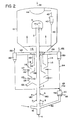
- FIG. 2 A second embodiment of the present invention is shown in Fig. 2 where like-numbered items are the same as in Fig. 1.
- the catalyst in bed 112 passes down through stripper 114 having perforated trays 116 (baffles) attached to sidewalls 115, a first cylinder 120 and a second cylinder 124. Both cylinders are concentric with the sidewalls 115 and the riser 2.
- a first inside perforated tray 118 is attached to first cylinder 120 and a second inside perforated tray 122 is attached to second cylinder 124.
- a top portion of cylinder 124 is inserted into first cylinder 120.
- Conduit 126 communicates with both cylinders 120, 124.
- first cylinder 120 has a top wall 121' to keep out catalyst from bed 112.
- Catalyst passes down through an annulus between sidewall 115 and cylinder 120 and contacts perforated trays 118 and 116. Stripping gas from a conduit 117 passes into a header 119 located below tray 116, and strips downwardly passing catalyst. Elutriatable catalyst rises into an annulus between cylinder 120 and cylinder 124. The remaining catalyst continues down to perforated trays 122 and 121. More stripping gas, from conduit 123 and header 125 under tray 121, contacts falling catalyst. Some catalyst elutes up into an annulus between cylinder 124 and riser 2. Less elutriatable catalyst continues down through conduit 128 to the regenerator (not shown).
- the elutriated catalyst portions pass in parallel, through the annulus between cylinders 120, 124 and cylinder 124 and riser 2, through conduit 126 to cyclones 130, which separate gas from catalyst. Two to eight cyclones 130 would be typically provided.
- the gas passes through overhead conduits 132 to vessel 10.
- the catalyst is discharged via diplegs 134 to the optional, but preferred, second stripper 56 and recycled to riser 2.
- the more elutriatable catalyst has a higher ratio of intermediate pore zeolite to large pore zeolite than the conventional catalyst which exits the stripper via conduit 128.
- the more elutriatable catalyst in bed 112 can freely pass up through cylinders 120, 124 and conduit 126 in bed 112, rather than push all the way through the catalyst bed 112 for quicker and more efficient separation of more from less elutriatable catalyst.
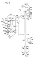
- Fig. 4 shows a third embodiment of the present invention, with stripper 244 external to a vessel 200.
- catalyst from conduit 236, attached to a regenerator (not shown) catalyst from conduit 262 and a lift gas stream 204 pass upwardly through a riser 202.
- a vacuum gas oil (VGO) stream 206 is added and passes up through the riser which discharges into vessel 200.
- the lift gas 204 contains C2-C4 olefins.
- the lift gas 204 contains ethylene and an optional feedstream 209, comprising olefins having 3 to 4 carbon atoms, is injected into the riser 202 between where the lift gas 204 and VGO stream 206 enters the riser.
- the riser discharges into a riser cyclone 208.
- the cyclone 208 separates gas from catalyst. Catalyst is discharged via dipleg 212 to catalyst bed 214. Gas passes via overhead conduit 210 to a cyclone 220 which discharges catalyst through dipleg 224 to bed 214. The gas passes up through a conduit 222 to plenum chamber 230, and through conduit 232 out of the reactor vessel 200 to downstream processing, such as fractionation (not shown).
- Catalyst in bed 214 is a stripped with from stripping gas conduit 218 attached to a header 219. Stripped catalyst passes via conduit 238 to catalyst bed 242 in stripper 244.
- Stripper vessel 244 contains cylinder 254 attached to inside perforated tray 252, top wall 255, cylinder 258 attached to a second inside perforated tray 256, and annular outer perforated trays 246, 247 attached to the sidewalls 245.
- the catalyst in bed 242 passes down and contacts trays 252 and 246.
- Stripping gas, from conduit 264, attached to a header 265 located under tray 246, passes up through tray 246 to strip downwardly passing catalyst.
- Elutriatable catalyst passes up through an annulus between the first and second cylinders 254 and 258. Less elutriatable catalyst continues down to trays 256 and 247.
- Stripping gas from conduit 266 and header 267 passes through tray 247 to strip the catalyst and to separate an elutriatable portion of catalyst which passes up through cylinder 258. Less elutriatable catalyst continues down and contacts a conical perforated tray 250 and annular perforated tray 248. More stripping gas from conduit 268 header 269 passes through trays 248 and 250. A third portion of catalyst passes through cylinder 258. The remaining less elutriatable catalyst passes down via through conduit 228, to a regenerator, not shown.
- Elutriated catalyst passes up in parallel through the cylinders 254, 258 and conduit 270 to a cyclone 272 which separates gas from catalyst.
- the gas passes up through cyclone withdrawal conduit 274 to vessel 200.
- the catalyst passes via dipleg 276 to a second stripper 256. Stripping gas from conduit 258 and header 260 produce stripped catalyst which recycles via conduit 262 to riser 202.
- Gaseous effluent passes via conduit 263 to vessel 200.
- the less elutriatable catalyst in conduit 228 has a higher ratio of large pore zeolite to intermediate pore zeolite than the catalyst in conduit 270.
- Stripper 244 efficiently separates more elutriatable from less elutriatable because the separated particles do not have to push all the way through catalyst bed 242.
Landscapes
- Chemical & Material Sciences (AREA)
- Oil, Petroleum & Natural Gas (AREA)
- Organic Chemistry (AREA)
- Chemical Kinetics & Catalysis (AREA)
- Engineering & Computer Science (AREA)
- General Chemical & Material Sciences (AREA)
- Production Of Liquid Hydrocarbon Mixture For Refining Petroleum (AREA)
- Catalysts (AREA)
- Devices And Processes Conducted In The Presence Of Fluids And Solid Particles (AREA)
Applications Claiming Priority (2)
| Application Number | Priority Date | Filing Date | Title |
|---|---|---|---|
| US903367 | 1986-09-03 | ||
| US06/903,367 US4787967A (en) | 1986-09-03 | 1986-09-03 | Process for two-phase fluid catalytic cracking system |
Related Parent Applications (1)
| Application Number | Title | Priority Date | Filing Date |
|---|---|---|---|
| EP87307766.3 Division | 1987-09-03 |
Publications (2)
| Publication Number | Publication Date |
|---|---|
| EP0453000A2 true EP0453000A2 (fr) | 1991-10-23 |
| EP0453000A3 EP0453000A3 (en) | 1991-11-06 |
Family
ID=25417386
Family Applications (2)
| Application Number | Title | Priority Date | Filing Date |
|---|---|---|---|
| EP19910111632 Withdrawn EP0453000A3 (en) | 1986-09-03 | 1987-09-03 | Process an apparatus for two-phase fluid catalytic cracking |
| EP87307766A Expired EP0259153B1 (fr) | 1986-09-03 | 1987-09-03 | Procédé pour le craquage catalytique fluidisé en deux phases |
Family Applications After (1)
| Application Number | Title | Priority Date | Filing Date |
|---|---|---|---|
| EP87307766A Expired EP0259153B1 (fr) | 1986-09-03 | 1987-09-03 | Procédé pour le craquage catalytique fluidisé en deux phases |
Country Status (6)
| Country | Link |
|---|---|
| US (1) | US4787967A (fr) |
| EP (2) | EP0453000A3 (fr) |
| JP (1) | JPS63116734A (fr) |
| AU (1) | AU609735B2 (fr) |
| CA (1) | CA1297061C (fr) |
| DE (1) | DE3777920D1 (fr) |
Cited By (1)
| Publication number | Priority date | Publication date | Assignee | Title |
|---|---|---|---|---|
| WO2010067379A2 (fr) | 2008-12-10 | 2010-06-17 | Reliance Industries Limited | Procédé de craquage catalytique fluide pour la production de propylène et d'éthylène avec un rendement amélioré |
Families Citing this family (28)
| Publication number | Priority date | Publication date | Assignee | Title |
|---|---|---|---|---|
| US4927606A (en) * | 1986-05-29 | 1990-05-22 | Uop | FCC Stripping apparatus |
| US4957617A (en) * | 1986-09-03 | 1990-09-18 | Mobil Oil Corporation | Fluid catalytic cracking |
| US4863585A (en) * | 1986-09-03 | 1989-09-05 | Mobil Oil Corporation | Fluidized catalytic cracking process utilizing a C3-C4 paraffin-rich Co-feed and mixed catalyst system with selective reactivation of the medium pore silicate zeolite component thereofo |
| US4892643A (en) * | 1986-09-03 | 1990-01-09 | Mobil Oil Corporation | Upgrading naphtha in a single riser fluidized catalytic cracking operation employing a catalyst mixture |
| US4787967A (en) * | 1986-09-03 | 1988-11-29 | Mobil Oil Corporation | Process for two-phase fluid catalytic cracking system |
| US4990314A (en) * | 1986-09-03 | 1991-02-05 | Mobil Oil Corporation | Process and apparatus for two-phase fluid catalytic cracking system |
| US4963328A (en) * | 1987-01-15 | 1990-10-16 | Mobil Oil Corporation | Short contact time fluid catalytic cracking apparatus |
| FR2610638B1 (fr) * | 1987-02-11 | 1990-04-13 | Total France | Perfectionnements aux procedes et dispositifs pour le craquage catalytique de charges d'hydrocarbures |
| US5051164A (en) * | 1987-09-04 | 1991-09-24 | Mobil Oil Corporation | Crystalline porous silicate composite and its use in catalytic cracking |
| US4927522A (en) * | 1988-12-30 | 1990-05-22 | Mobil Oil Corporation | Multiple feed point catalytic cracking process using elutriable catalyst mixture |
| GB2233663A (en) * | 1989-07-12 | 1991-01-16 | Exxon Research Engineering Co | Catalyst stripper unit and process in catalytic cracking operations |
| US5141630A (en) * | 1990-03-15 | 1992-08-25 | Lyondell Petrochemical Company | Separation process employing two stripping gases |
| US5248408A (en) * | 1991-03-25 | 1993-09-28 | Mobil Oil Corporation | Catalytic cracking process and apparatus with refluxed spent catalyst stripper |
| US5209840A (en) * | 1991-10-02 | 1993-05-11 | Texaco Inc. | Separation of active catalyst particles from spent catalyst particles by air elutriation |
| US5538623A (en) * | 1993-12-17 | 1996-07-23 | Johnson; David L. | FCC catalyst stripping with vapor recycle |
| EP1013743B1 (fr) * | 1998-12-21 | 2005-02-02 | INDIAN OIL CORPORATION Ltd. | Procédé de craquage catalytique en lit fluidisé |
| US6656344B1 (en) | 1998-12-23 | 2003-12-02 | Marri Rama Rao | Fluidized catalytic cracking process |
| US6680030B2 (en) * | 1999-12-29 | 2004-01-20 | Uop Llc | Stripping process with horizontal baffles |
| US6538169B1 (en) * | 2000-11-13 | 2003-03-25 | Uop Llc | FCC process with improved yield of light olefins |
| DE10219863B4 (de) * | 2002-05-03 | 2014-03-27 | Indian Oil Corporation Limited | Rückstandscrackvorrichtung mit Katalysator- und Adsorptionsmittelregeneratoren und Verfahren hierfür |
| US7381322B2 (en) * | 2002-05-08 | 2008-06-03 | Indian Oil Corporation Limited | Resid cracking apparatus with catalyst and adsorbent regenerators and a process thereof |
| US7682501B2 (en) * | 2004-12-23 | 2010-03-23 | Abb Lummus Global, Inc. | Processing of different feeds in a fluid catalytic cracking unit |
| US20090124842A1 (en) * | 2006-07-12 | 2009-05-14 | Reagan William J | Fcc catalyst for light olefin production |
| US8007728B2 (en) * | 2008-12-11 | 2011-08-30 | Uop Llc | System, apparatus, and process for cracking a hydrocarbon feed |
| US9567272B2 (en) | 2014-06-26 | 2017-02-14 | Uop Llc | FCC process with a dehydrogenation zone for max propylene production |
| CN106269508B (zh) * | 2016-09-08 | 2018-05-29 | 清华大学 | 一种颗粒混合物的环形流化床分离器及其参与的气固反应器系统 |
| MY197653A (en) * | 2019-07-15 | 2023-06-30 | Lummus Technology Inc | Fluid catalytic cracking process and apparatus for maximizing light olefin yield and other applications |
| CN114405418B (zh) * | 2022-02-25 | 2023-04-14 | 北京石油化工工程有限公司 | 甲醇和丙酸甲酯为原料生产甲基丙烯酸甲酯的系统及方法 |
Citations (3)
| Publication number | Priority date | Publication date | Assignee | Title |
|---|---|---|---|---|
| US3380911A (en) * | 1966-02-15 | 1968-04-30 | Mobil Oil Corp | Method for converting hydrocarbons in two stages |
| US4116814A (en) * | 1977-07-18 | 1978-09-26 | Mobil Oil Corporation | Method and system for effecting catalytic cracking of high boiling hydrocarbons with fluid conversion catalysts |
| EP0127285A2 (fr) * | 1983-04-26 | 1984-12-05 | Mobil Oil Corporation | Injection secondaire de zéolite du type ZSM-5 dans le craquage catalytique |
Family Cites Families (26)
| Publication number | Priority date | Publication date | Assignee | Title |
|---|---|---|---|---|
| US2515155A (en) * | 1941-07-12 | 1950-07-11 | Standard Oil Dev Co | Apparatus for separating solids from gases |
| US3617497A (en) * | 1969-06-25 | 1971-11-02 | Gulf Research Development Co | Fluid catalytic cracking process with a segregated feed charged to the reactor |
| US3758403A (en) * | 1970-10-06 | 1973-09-11 | Mobil Oil | Olites catalytic cracking of hydrocarbons with mixture of zsm-5 and other ze |
| US3748251A (en) * | 1971-04-20 | 1973-07-24 | Mobil Oil Corp | Dual riser fluid catalytic cracking with zsm-5 zeolite |
| US3847793A (en) * | 1972-12-19 | 1974-11-12 | Mobil Oil | Conversion of hydrocarbons with a dual cracking component catalyst comprising zsm-5 type material |
| US3856659A (en) * | 1972-12-19 | 1974-12-24 | Mobil Oil Corp | Multiple reactor fcc system relying upon a dual cracking catalyst composition |
| US3894934A (en) * | 1972-12-19 | 1975-07-15 | Mobil Oil Corp | Conversion of hydrocarbons with mixture of small and large pore crystalline zeolite catalyst compositions to accomplish cracking cyclization, and alkylation reactions |
| US3926778A (en) * | 1972-12-19 | 1975-12-16 | Mobil Oil Corp | Method and system for controlling the activity of a crystalline zeolite cracking catalyst |
| US3926843A (en) * | 1973-03-26 | 1975-12-16 | Mobil Oil Corp | Fcc ' 'multi-stage regeneration procedure |
| US3894931A (en) * | 1974-04-02 | 1975-07-15 | Mobil Oil Corp | Method for improving olefinic gasoline product of low conversion fluid catalytic cracking |
| US4035285A (en) * | 1974-05-28 | 1977-07-12 | Mobil Oil Corporation | Hydrocarbon conversion process |
| US4444722A (en) * | 1976-11-18 | 1984-04-24 | Mobil Oil Corporation | System for regenerating fluidizable catalyst particles |
| US4118337A (en) * | 1977-06-20 | 1978-10-03 | Mobil Oil Corporation | Method for regenerating fluidizable solid particles employed in hydrocarbon conversion |
| US4146465A (en) * | 1977-07-08 | 1979-03-27 | W. R. Grace & Co. | Addition of olefins to cat cracker feed to modify product selectivity and quality |
| US4325833A (en) * | 1980-06-27 | 1982-04-20 | Chevron Research Company | Three-stage catalyst regeneration |
| US4336160A (en) * | 1980-07-15 | 1982-06-22 | Dean Robert R | Method and apparatus for cracking residual oils |
| US4331533A (en) * | 1980-07-15 | 1982-05-25 | Dean Robert R | Method and apparatus for cracking residual oils |
| US4427537A (en) * | 1982-03-17 | 1984-01-24 | Dean Robert R | Method and means for preparing and dispersing atomed hydrocarbon with fluid catalyst particles in a reactor zone |
| US4404095A (en) * | 1982-07-22 | 1983-09-13 | Mobil Oil Corporation | Method and means for separating gaseous materials from finely divided catalyst particles |
| US4481103A (en) * | 1983-10-19 | 1984-11-06 | Mobil Oil Corporation | Fluidized catalytic cracking process with long residence time steam stripper |
| US4502947A (en) * | 1984-05-21 | 1985-03-05 | Mobil Oil Corporation | Closed cyclone FCC catalyst separation method and apparatus |
| US4605491A (en) * | 1984-07-18 | 1986-08-12 | Mobil Oil Corporation | FCC catalyst stripping method |
| US4752375A (en) * | 1986-09-03 | 1988-06-21 | Mobil Oil Corporation | Single riser fluidized catalytic cracking process utilizing a C3-4 paraffin-rich co-feed and mixed catalyst system |
| US4787967A (en) * | 1986-09-03 | 1988-11-29 | Mobil Oil Corporation | Process for two-phase fluid catalytic cracking system |
| US4717466A (en) * | 1986-09-03 | 1988-01-05 | Mobil Oil Corporation | Multiple riser fluidized catalytic cracking process utilizing hydrogen and carbon-hydrogen contributing fragments |
| US4749470A (en) * | 1986-09-03 | 1988-06-07 | Mobil Oil Corporation | Residuum fluid catalytic cracking process and apparatus using microwave energy |
-
1986
- 1986-09-03 US US06/903,367 patent/US4787967A/en not_active Expired - Fee Related
-
1987
- 1987-09-03 EP EP19910111632 patent/EP0453000A3/en not_active Withdrawn
- 1987-09-03 DE DE8787307766T patent/DE3777920D1/de not_active Expired - Fee Related
- 1987-09-03 AU AU77901/87A patent/AU609735B2/en not_active Ceased
- 1987-09-03 JP JP62221173A patent/JPS63116734A/ja active Pending
- 1987-09-03 EP EP87307766A patent/EP0259153B1/fr not_active Expired
- 1987-09-03 CA CA000546031A patent/CA1297061C/fr not_active Expired - Lifetime
Patent Citations (3)
| Publication number | Priority date | Publication date | Assignee | Title |
|---|---|---|---|---|
| US3380911A (en) * | 1966-02-15 | 1968-04-30 | Mobil Oil Corp | Method for converting hydrocarbons in two stages |
| US4116814A (en) * | 1977-07-18 | 1978-09-26 | Mobil Oil Corporation | Method and system for effecting catalytic cracking of high boiling hydrocarbons with fluid conversion catalysts |
| EP0127285A2 (fr) * | 1983-04-26 | 1984-12-05 | Mobil Oil Corporation | Injection secondaire de zéolite du type ZSM-5 dans le craquage catalytique |
Cited By (3)
| Publication number | Priority date | Publication date | Assignee | Title |
|---|---|---|---|---|
| WO2010067379A2 (fr) | 2008-12-10 | 2010-06-17 | Reliance Industries Limited | Procédé de craquage catalytique fluide pour la production de propylène et d'éthylène avec un rendement amélioré |
| EP2364343A2 (fr) * | 2008-12-10 | 2011-09-14 | Reliance Industries Limited | Procédé de craquage catalytique fluide pour la production de propylène et d'éthylène avec un rendement amélioré |
| EP2364343A4 (fr) * | 2008-12-10 | 2013-11-20 | Reliance Ind Ltd | Procédé de craquage catalytique fluide pour la production de propylène et d'éthylène avec un rendement amélioré |
Also Published As
| Publication number | Publication date |
|---|---|
| EP0453000A3 (en) | 1991-11-06 |
| DE3777920D1 (de) | 1992-05-07 |
| EP0259153A1 (fr) | 1988-03-09 |
| US4787967A (en) | 1988-11-29 |
| CA1297061C (fr) | 1992-03-10 |
| AU609735B2 (en) | 1991-05-09 |
| AU7790187A (en) | 1988-03-10 |
| JPS63116734A (ja) | 1988-05-21 |
| EP0259153B1 (fr) | 1992-04-01 |
Similar Documents
| Publication | Publication Date | Title |
|---|---|---|
| EP0259153B1 (fr) | Procédé pour le craquage catalytique fluidisé en deux phases | |
| AU620134B2 (en) | Upgrading naphtha in a multiple riser fluid catalytic cracking operation employing a catalyst mixture | |
| US4830728A (en) | Upgrading naphtha in a multiple riser fluid catalytic cracking operation employing a catalyst mixture | |
| US4892643A (en) | Upgrading naphtha in a single riser fluidized catalytic cracking operation employing a catalyst mixture | |
| US4116814A (en) | Method and system for effecting catalytic cracking of high boiling hydrocarbons with fluid conversion catalysts | |
| US4490241A (en) | Secondary injection of ZSM-5 type zeolite in catalytic cracking | |
| US4717466A (en) | Multiple riser fluidized catalytic cracking process utilizing hydrogen and carbon-hydrogen contributing fragments | |
| US4814068A (en) | Fluid catalytic cracking process and apparatus for more effective regeneration of zeolite catalyst | |
| US20060178546A1 (en) | Method and apparatus for making a middle distillate product and lower olefins from a hydrocarbon feedstock | |
| US4865718A (en) | Maximizing distillate production in a fluid catalytic cracking operation employing a mixed catalyst system | |
| US4871446A (en) | Catalytic cracking process employing mixed catalyst system | |
| US4895636A (en) | FCC process with catalyst separation | |
| US4863585A (en) | Fluidized catalytic cracking process utilizing a C3-C4 paraffin-rich Co-feed and mixed catalyst system with selective reactivation of the medium pore silicate zeolite component thereofo | |
| US4826586A (en) | Single riser fluidized catalytic cracking process utilizing a C3-4 paraffin-rich co-feed and mixed catalyst system | |
| US4990314A (en) | Process and apparatus for two-phase fluid catalytic cracking system | |
| US4874503A (en) | Multiple riser fluidized catalytic cracking process employing a mixed catalyst | |
| US4752375A (en) | Single riser fluidized catalytic cracking process utilizing a C3-4 paraffin-rich co-feed and mixed catalyst system | |
| US4961907A (en) | Catalytic cracking apparatus employing mixed catalyst system | |
| US4971766A (en) | Apparatus for FCC process with catalyst separation | |
| US5234575A (en) | Catalytic cracking process utilizing an iso-olefin enhancer catalyst additive | |
| US4888103A (en) | Process of stripping in a catalytic cracking operation employing a catalyst mixture which includes a shape selective medium pore silicate zeolite component | |
| US4861741A (en) | Mixed catalyst system and catalytic conversion process employing same | |
| EP0259155B1 (fr) | Procédé pour le stripping d'un catalyseur d'un zone de réaction pour le craquage catalytique | |
| EP0259154B1 (fr) | Revalorisation de naphte dans une colonne montante d'une opération de craquage catalytique employant un mélange de catalyseurs | |
| WO1991003528A1 (fr) | Operation de craquage catalytique de fluide a l'aide d'un systeme de catalyseurs melanges |
Legal Events
| Date | Code | Title | Description |
|---|---|---|---|
| PUAI | Public reference made under article 153(3) epc to a published international application that has entered the european phase |
Free format text: ORIGINAL CODE: 0009012 |
|
| PUAL | Search report despatched |
Free format text: ORIGINAL CODE: 0009013 |
|
| 17P | Request for examination filed |
Effective date: 19910712 |
|
| AC | Divisional application: reference to earlier application |
Ref document number: 259153 Country of ref document: EP |
|
| AK | Designated contracting states |
Kind code of ref document: A2 Designated state(s): BE DE FR GB IT NL |
|
| AK | Designated contracting states |
Kind code of ref document: A3 Designated state(s): BE DE FR GB IT NL |
|
| 17Q | First examination report despatched |
Effective date: 19921030 |
|
| STAA | Information on the status of an ep patent application or granted ep patent |
Free format text: STATUS: THE APPLICATION HAS BEEN WITHDRAWN |
|
| 18W | Application withdrawn |
Withdrawal date: 19930629 |