EP0452902A2 - Hollow fiber type liquid processing apparatus - Google Patents
Hollow fiber type liquid processing apparatus Download PDFInfo
- Publication number
- EP0452902A2 EP0452902A2 EP91106135A EP91106135A EP0452902A2 EP 0452902 A2 EP0452902 A2 EP 0452902A2 EP 91106135 A EP91106135 A EP 91106135A EP 91106135 A EP91106135 A EP 91106135A EP 0452902 A2 EP0452902 A2 EP 0452902A2
- Authority
- EP
- European Patent Office
- Prior art keywords
- blood
- annular elastic
- annular
- housing
- elastic member
- Prior art date
- Legal status (The legal status is an assumption and is not a legal conclusion. Google has not performed a legal analysis and makes no representation as to the accuracy of the status listed.)
- Ceased
Links
- 239000012510 hollow fiber Substances 0.000 title claims abstract description 126
- 238000012545 processing Methods 0.000 title claims abstract description 86
- 239000007788 liquid Substances 0.000 title claims abstract description 47
- 210000004369 blood Anatomy 0.000 claims abstract description 338
- 239000008280 blood Substances 0.000 claims abstract description 338
- 238000005192 partition Methods 0.000 claims abstract description 87
- 238000000465 moulding Methods 0.000 claims abstract description 31
- 230000002093 peripheral effect Effects 0.000 claims abstract description 17
- 239000011796 hollow space material Substances 0.000 claims description 17
- 239000000463 material Substances 0.000 description 19
- 238000000034 method Methods 0.000 description 17
- 238000010276 construction Methods 0.000 description 10
- 229920002379 silicone rubber Polymers 0.000 description 10
- 239000004945 silicone rubber Substances 0.000 description 10
- PPBRXRYQALVLMV-UHFFFAOYSA-N Styrene Chemical compound C=CC1=CC=CC=C1 PPBRXRYQALVLMV-UHFFFAOYSA-N 0.000 description 8
- 229920001577 copolymer Polymers 0.000 description 8
- 239000000835 fiber Substances 0.000 description 8
- 238000002347 injection Methods 0.000 description 7
- 239000007924 injection Substances 0.000 description 7
- 238000001746 injection moulding Methods 0.000 description 7
- 239000012528 membrane Substances 0.000 description 7
- 239000002184 metal Substances 0.000 description 7
- 229920003225 polyurethane elastomer Polymers 0.000 description 7
- 238000000502 dialysis Methods 0.000 description 6
- -1 etc.) Polymers 0.000 description 6
- 238000003780 insertion Methods 0.000 description 6
- 230000037431 insertion Effects 0.000 description 6
- 230000000717 retained effect Effects 0.000 description 6
- 229920002678 cellulose Polymers 0.000 description 5
- 239000001913 cellulose Substances 0.000 description 5
- 239000003795 chemical substances by application Substances 0.000 description 5
- 238000004382 potting Methods 0.000 description 5
- 229920005989 resin Polymers 0.000 description 5
- 239000011347 resin Substances 0.000 description 5
- 229920000181 Ethylene propylene rubber Polymers 0.000 description 4
- 230000035602 clotting Effects 0.000 description 4
- 239000013013 elastic material Substances 0.000 description 4
- 229920001971 elastomer Polymers 0.000 description 4
- 239000000806 elastomer Substances 0.000 description 4
- 229920003049 isoprene rubber Polymers 0.000 description 4
- 239000004417 polycarbonate Substances 0.000 description 4
- 229920000515 polycarbonate Polymers 0.000 description 4
- 229920006124 polyolefin elastomer Polymers 0.000 description 4
- 239000004627 regenerated cellulose Substances 0.000 description 4
- 239000004636 vulcanized rubber Substances 0.000 description 4
- 208000007536 Thrombosis Diseases 0.000 description 3
- 229920002301 cellulose acetate Polymers 0.000 description 3
- 230000015271 coagulation Effects 0.000 description 3
- 238000005345 coagulation Methods 0.000 description 3
- 239000002131 composite material Substances 0.000 description 3
- 239000004814 polyurethane Substances 0.000 description 3
- 238000007789 sealing Methods 0.000 description 3
- 238000012360 testing method Methods 0.000 description 3
- NLHHRLWOUZZQLW-UHFFFAOYSA-N Acrylonitrile Chemical compound C=CC#N NLHHRLWOUZZQLW-UHFFFAOYSA-N 0.000 description 2
- 229920000219 Ethylene vinyl alcohol Polymers 0.000 description 2
- 239000005062 Polybutadiene Substances 0.000 description 2
- 239000004698 Polyethylene Substances 0.000 description 2
- 239000004743 Polypropylene Substances 0.000 description 2
- 239000004793 Polystyrene Substances 0.000 description 2
- 229920001893 acrylonitrile styrene Polymers 0.000 description 2
- 230000015572 biosynthetic process Effects 0.000 description 2
- 230000023555 blood coagulation Effects 0.000 description 2
- 210000004072 lung Anatomy 0.000 description 2
- 210000002381 plasma Anatomy 0.000 description 2
- 229920002857 polybutadiene Polymers 0.000 description 2
- 229920000573 polyethylene Polymers 0.000 description 2
- 229920000098 polyolefin Polymers 0.000 description 2
- 229920005672 polyolefin resin Polymers 0.000 description 2
- 229920001155 polypropylene Polymers 0.000 description 2
- 229920002223 polystyrene Polymers 0.000 description 2
- SCUZVMOVTVSBLE-UHFFFAOYSA-N prop-2-enenitrile;styrene Chemical compound C=CC#N.C=CC1=CC=CC=C1 SCUZVMOVTVSBLE-UHFFFAOYSA-N 0.000 description 2
- 229920000468 styrene butadiene styrene block copolymer Polymers 0.000 description 2
- 229920005992 thermoplastic resin Polymers 0.000 description 2
- 238000003466 welding Methods 0.000 description 2
- 241000283690 Bos taurus Species 0.000 description 1
- IAYPIBMASNFSPL-UHFFFAOYSA-N Ethylene oxide Chemical compound C1CO1 IAYPIBMASNFSPL-UHFFFAOYSA-N 0.000 description 1
- HTTJABKRGRZYRN-UHFFFAOYSA-N Heparin Chemical compound OC1C(NC(=O)C)C(O)OC(COS(O)(=O)=O)C1OC1C(OS(O)(=O)=O)C(O)C(OC2C(C(OS(O)(=O)=O)C(OC3C(C(O)C(O)C(O3)C(O)=O)OS(O)(=O)=O)C(CO)O2)NS(O)(=O)=O)C(C(O)=O)O1 HTTJABKRGRZYRN-UHFFFAOYSA-N 0.000 description 1
- 238000005452 bending Methods 0.000 description 1
- 230000017531 blood circulation Effects 0.000 description 1
- 230000004087 circulation Effects 0.000 description 1
- 239000003086 colorant Substances 0.000 description 1
- 229960002897 heparin Drugs 0.000 description 1
- 229920000669 heparin Polymers 0.000 description 1
- 238000004519 manufacturing process Methods 0.000 description 1
- 238000002844 melting Methods 0.000 description 1
- 230000008018 melting Effects 0.000 description 1
- 238000002156 mixing Methods 0.000 description 1
- 229920002635 polyurethane Polymers 0.000 description 1
- 239000012266 salt solution Substances 0.000 description 1
- 238000012546 transfer Methods 0.000 description 1
- 238000005406 washing Methods 0.000 description 1
- XLYOFNOQVPJJNP-UHFFFAOYSA-N water Substances O XLYOFNOQVPJJNP-UHFFFAOYSA-N 0.000 description 1
Images


Classifications
-
- B—PERFORMING OPERATIONS; TRANSPORTING
- B01—PHYSICAL OR CHEMICAL PROCESSES OR APPARATUS IN GENERAL
- B01D—SEPARATION
- B01D65/00—Accessories or auxiliary operations, in general, for separation processes or apparatus using semi-permeable membranes
-
- B—PERFORMING OPERATIONS; TRANSPORTING
- B01—PHYSICAL OR CHEMICAL PROCESSES OR APPARATUS IN GENERAL
- B01D—SEPARATION
- B01D61/00—Processes of separation using semi-permeable membranes, e.g. dialysis, osmosis or ultrafiltration; Apparatus, accessories or auxiliary operations specially adapted therefor
- B01D61/24—Dialysis ; Membrane extraction
- B01D61/30—Accessories; Auxiliary operation
-
- B—PERFORMING OPERATIONS; TRANSPORTING
- B01—PHYSICAL OR CHEMICAL PROCESSES OR APPARATUS IN GENERAL
- B01D—SEPARATION
- B01D63/00—Apparatus in general for separation processes using semi-permeable membranes
- B01D63/02—Hollow fibre modules
- B01D63/021—Manufacturing thereof
- B01D63/0233—Manufacturing thereof forming the bundle
-
- B—PERFORMING OPERATIONS; TRANSPORTING
- B29—WORKING OF PLASTICS; WORKING OF SUBSTANCES IN A PLASTIC STATE IN GENERAL
- B29C—SHAPING OR JOINING OF PLASTICS; SHAPING OF MATERIAL IN A PLASTIC STATE, NOT OTHERWISE PROVIDED FOR; AFTER-TREATMENT OF THE SHAPED PRODUCTS, e.g. REPAIRING
- B29C70/00—Shaping composites, i.e. plastics material comprising reinforcements, fillers or preformed parts, e.g. inserts
- B29C70/68—Shaping composites, i.e. plastics material comprising reinforcements, fillers or preformed parts, e.g. inserts by incorporating or moulding on preformed parts, e.g. inserts or layers, e.g. foam blocks
- B29C70/681—Component parts, details or accessories; Auxiliary operations
- B29C70/683—Pretreatment of the preformed part, e.g. insert
-
- B—PERFORMING OPERATIONS; TRANSPORTING
- B29—WORKING OF PLASTICS; WORKING OF SUBSTANCES IN A PLASTIC STATE IN GENERAL
- B29C—SHAPING OR JOINING OF PLASTICS; SHAPING OF MATERIAL IN A PLASTIC STATE, NOT OTHERWISE PROVIDED FOR; AFTER-TREATMENT OF THE SHAPED PRODUCTS, e.g. REPAIRING
- B29C70/00—Shaping composites, i.e. plastics material comprising reinforcements, fillers or preformed parts, e.g. inserts
- B29C70/68—Shaping composites, i.e. plastics material comprising reinforcements, fillers or preformed parts, e.g. inserts by incorporating or moulding on preformed parts, e.g. inserts or layers, e.g. foam blocks
- B29C70/74—Moulding material on a relatively small portion of the preformed part, e.g. outsert moulding
-
- B—PERFORMING OPERATIONS; TRANSPORTING
- B01—PHYSICAL OR CHEMICAL PROCESSES OR APPARATUS IN GENERAL
- B01D—SEPARATION
- B01D2313/00—Details relating to membrane modules or apparatus
- B01D2313/04—Specific sealing means
- B01D2313/041—Gaskets or O-rings
-
- B—PERFORMING OPERATIONS; TRANSPORTING
- B01—PHYSICAL OR CHEMICAL PROCESSES OR APPARATUS IN GENERAL
- B01D—SEPARATION
- B01D2313/00—Details relating to membrane modules or apparatus
- B01D2313/21—Specific headers, end caps
Definitions
- This invention relates to the hollow fiber type liquid processing apparatus utilized for a hollow fiber type of artificial dialyzer, artificial lung, blood plasma separator, and the like.
- the typical application is a hollow fiber type artificial dialyzer.
- the general construction of this type of artificial dialyzer is such that a bundle of many hollow fibers each made of a dialyzation membrane is housed in a cylindrical housing provided with an inlet and an outlet of dialyzation liquid, both end of the hollow fiber bundle are retained in a liquid-tight fashion by partitions made of a potting agent and secured to each end of the housing, and cap-like blood ports provided respectively with a blood inlet and a blood outlet are attached to the ends of the housing.
- hydrophilic membranes of regenerated cellulose such as cellulose acetate and cuprammonium cellulose are used.
- polyuretane and others are used for the dialyzation membrane.
- the blood ports used in the existing blood dialyzers have generally a blood inlet or outlet and an annular groove. They are attached to the ends of the housing by means of threaded joints with an O-ring made of silicone rubber or a like material in the annular groove.
- the blood ports with the same inside shape are used for the entrance and exit blood ports though they are marked so by different colors. Because of this inside shape of the blood ports, there is a problem that coagulation of blood can occur while passing through the inside of dialyzer.
- An object of the present invention is to solve the problems of the conventional apparatus as described above and provide an improved blood processing apparatus which can seal the blood ports and the partitions liquid-tight securely without using O-rings.
- Another object of the present invention is to solve the above problems of the conventional apparatus and provide an improved blood processing apparatus which can seal the blood ports and the partitions liquid-tight securely without O-rings, prevent occurrence of coagulation of circulating blood, formation of blood clots caused by contact with burrs and mixing of broken burrs into the blood.
- Further object of the present invention is to solve the problems of the conventional apparatus as described above and provide an improved blood processing apparatus which can substantially equally distribute blood to all the hollow fibers and decrease coagulation of blood.
- a hollow fiber type blood processing apparatus of the present invention comprises a housing, a bundle of hollow fibers which comprises a great number of hollow fibers for processing blood and is housed in the housing, an inlet and an outlet of a blood processing liquid which are provided near each end of the housing, partitions which secure each end of the bundle of hollow fibers to each end of the housing, an entrance blood port which has a blood inlet and is attached to one end of the housing, and an exit blood port which has a blood outlet and is attached to the other end of the housing, wherein the entrance blood port and exit blood port have each an annular groove at the peripheral area of their inside surface and an annular elastic member conjoined in the annular groove by molding, the annular elastic members have each an annular elastic rib extended out of the annular groove, and the entrance blood port and the exit blood port are attached to the housing with their annular elastic member pressed to the corresponding partition and the annular elastic rib of the annular elastic member pinched between the partition and an annular rib which defines
- a hollow fiber type liquid processing apparatus of the present invention comprises the housing, a bundle of hollow fibers which comprises a great number of hollow fibers for processing blood and is housed in the housing, an inlet and an outlet for a blood processing liquid which are provided near each ends of the housing, partitions which secure each end of the bundle of hollow fibers to each end of the housing, an entrance blood port which has a blood inlet and is attached to one end of the housing, and an exit blood port which has a blood outlet and is attached to the other end of the housing, wherein the entrance blood port and the exit blood port have each an annular groove at the peripheral area of their inside surface and an annular elastic member secured in each annular groove, and an annular hollow space formed between the annular elastic member and an annular rib which defines the radially-inner side of the annular groove in the inside surface of each blood port and the entrance blood port and the exit blood port are attached to the housing with their annular elastic member pressed to the corresponding partition.
- a hollow fiber type liquid processing apparatus of the present invention comprises the housing, a bundle of hollow fibers which comprises a great number of hollow fibers for processing blood and is housed in the housing, an inlet and an outlet for a blood processing liquid which are provided near each ends of the housing, partitions which secure each end of the bundle of hollow fibers to each end of the housing, an entrance blood port which has a blood inlet and is attached to one end of the housing, and an exit blood port which has a blood outlet and is attached to the other end of the housing, wherein the entrance blood port and the exit blood port have different inside shape.
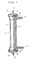
- FIG.1 is a part-sectional view of a hollow fiber type blood processing apparatus of an embodiment of the present invention.
- FIG.2 is an enlarged part-sectional view of a part of the blood port used in the hollow fiber type blood processing apparatus of an embodiment of the present invention.
- FIG.3 is an enlarged sectional view of a part of the blood port shown in FIG.2 attached to the housing.
- FIG.4 is an enlarged sectional view of a part of the blood port used in the hollow fiber type blood processing apparatus of another embodiment of the present invention.
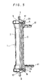
- FIG.5 is a part-sectional view of the hollow fiber type blood processing apparatus of another embodiment of the present invention.
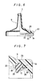
- FIG.6 is an enlarged part-sectional view of a part of the blood port used in the hollow fiber type blood processing apparatus of another embodiment of the present invention.
- FIG.7 is an enlarged sectional view of an area around the annular elastic element of the blood port shown in FIG.6.
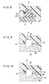
- FIG.8 is an enlarged sectional view of a part of the blood port shown in FIG.7 attached to the housing.
- FIG.9 shows a molding step of the blood port shown in FIG. 7.
- FIG. 10 shows a molding step of the blood port of the hollow fiber type blood processing apparatus of another embodiment of the present.
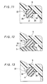
- FIG. 11 is an enlarged sectional view of an area around the annular elastic element of the blood port of the hollow fiber type blood processing apparatus of another embodiment of the present invention.
- FIG. 12 is an enlarged sectional view of a part of the blood port shown in FIG. 11 attached to the housing.
- FIG. 13 is an enlarged sectional view of an area around the annular elastic element of the blood port of the hollow fiber type blood processing apparatus of another embodiment of the present invention.
- FIG. 14 is an enlarged sectional view of a blood port used in a conventional hollow fiber type blood processing apparatus.
- FIG. 15 is an enlarged sectional view of an artificial dialyzer which embodies the hollow fiber type blood processing apparatus of the present invention.
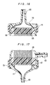
- FIG. 16 is an enlarged sectional view of the entrance blood port shown in FIG. 15.
- FIG. 17 is an enlarged sectional view of the exit blood port shown in FIG. 15.
- FIG. 18 is a illustration for explaining the inclination of the inside surface of the blood ports.
- a hollow fiber type liquid processing apparatus of the present invention is described using the embodiments shown in drawings.
- FIG. 1 is a part-sectional view of an embodiment of the hollow fiber type liquid processing apparatus of the present invention applied to an artificial dialyzer.
- FIG. 2 is an enlarged scale sectional view of the blood ports used in the artificial dialyzer shown in FIG. 1.
- a hollow fiber type liquid processing apparatus 1 comprises a housing 2, a bundle of hollow fibers 3 which comprises a great number of hollow fibers for processing blood and is housed in the housing 2, an inlet 11 and an outlet 12 of a blood processing liquid provided near each end of the housing 2, partitions 5 and 6 disposed at each end of the housing 2 and retaining each end of the bundle of hollow fibers 3, an entrance blood port 9 having a blood inlet 7 and attached to the end of the housing 2 on the side of the partitions 5, an exit blood port 10 having a blood outlet 8 and attached to the end of the housing 2 on the side of the partitions 6.
- the blood ports 9 and 10 each have a annular groove 26 formed in their inside surface near the circumference and an annular elastic member 17, 18 put in the annular groove 26.
- the annular elastic members 17 and 18 have an annular elastic rib 20 protruding out of the annular groove 26.
- the blood ports 9 and 10 are secured to the housing 2 in a manner that the annular elastic members 17 and 18 are pressed to the portions 5 and 6.
- the annular elastic rib 20 of the annular elastic members 7 and 8 is pinched between each partition 5, 6 and an annular rib 22 which defines the inner side of the annular groove 26 of each blood port 9 and 10.
- the annular elastic rib 20 is deformed by pressure and pinched between the annular rib 22 of the blood port 9 and the partition 5 to seal securely the gap between the blood port 9 and the partition 5 as shown in FIG. 3. Moreover, since the space between the annular rib 22 and the partition 5 is reduced, formation of blood clots due to the stagnation of blood within this space can be substantially prevented.
- hollow fibers for dialyzation are housed in the housing 2 filling the whole inner space of the housing 2.
- These hollow fibers are secured at their end to the ends of the housing 2 by means of the partitions 5 and 6 in a liquid tight fashion with the opening at their ends open.
- the space in the housing 2 is separated into a dialysis liquid chamber defined by the outside surface of the hollow fibers, the inside surface of the housing 2 and the partitions 5 and 6 and blood chambers defined within the hollow fibers.
- the housing 2 is formed of polycarbonate, acrylonitrile -styrene-copolymer, styrene, or butylene-styrene-copolymer.
- the housing 2 is a hollow cylinder and preferably a circular cylinder. This cylindrical housing is provided with the inlet 11 for a dialysis liquid at the side wall near one end and the outlet 12 of the liquid at the side wall near the other end.
- the hollow fibers 3 are hollow-fiber membranes for dialyzation which are made of regenerated cellulose (cellulose acetate, cuprammonium cellulose, etc.), cellulose derivatives, ethylene-vinyl alcohol copolymer and acrylonitrile copolymer and have a hydrophilic property.
- the hollow fibers 3 have a lumen extending through its length and a wall thickness of 5 to 35 ⁇ m,preferably 10 to 20 ⁇ m and an outer diameter of 50 to 500 ⁇ m, preferably 100 to 300 ⁇ m.
- the partitions 5 and 6 are made of a potting agent such as polyurethane or silicone-rubber. It is desirable that the partitions 5 and 6 have an area near the circumference with no fiber ends retained and the annular elastic member described below comes into contact with this area. This is to prevent the fiber ends from being blocked under the annular elastic member and utilize all the fibers in the housing.
- the blood ports are attached.
- the blood ports 9 and 10 of the embodiment shown in FIG. 1 have a joint portion 23, which fits to the end of the housing 2 and is secured to the housing 2 by welding using high frequency electromagnetic wave or ultrasonic vibration.
- annular elastic members 17 and 18 are conjoined by composite molding.
- the annular elastic members 17 and 18 are pressed to the partitions 5 and 6 and seal the peripheral areas of the partitions.
- annular groove 26 is formed in the peripheral area of the inside surface of the blood port 9.
- the sides of the annular groove 26 are defined by the radially-outside surface of the annular rib 22 and the radially-inside surface of the shoulder 24 in the inside surface of the blood port 9.
- the annular elastic member 17 is formed as a single part by filling an elastic material into the annular groove 26.
- the annular elastic member 17 has an annular elastic rib 20 which protrudes out of the groove 26, that is, downward from the annular elastic member 17. More specifically, it is preferable the annular elastic rib 20 is extended from the radially-inner side portion of the annular elastic member 17 and its outer diameter becomes smaller toward the top end.
- the annular elastic rib 20 becomes thinner toward the top end and is deformed toward the annular rib 22 of the blood port 9 without fail when pressed to the partition 5. It is more preferable that the radially-outer side of the annular elastic rib 20 is curved concave in about a quarter circle. The annular elastic rib 20 is then more readily deformed toward the annular rib 22.
- the cross-section of the annular elastic rib 20 may be substantially semicircular, substantially rectangular, substantially triangular or any other figures or in a shape whose top or bottom portion is broader than the breadth of the opening of the annular groove 26.
- the preferable dimensions of the annular groove 26 is about 2.0 to 5.0 mm in breadth and about 1.0 to 3.0 mm in depth.
- the height of the annular elastic rib 20 is preferably about 0.5 to 2.0 mm. When formed so as to become thinner toward the top end as shown in FIG. 2, the thickness is preferably about 2.0 to 5.0 mm at the bottom and less than about 2.5 mm at the top.
- the top end of the annular elastic rib 20 is preferably formed in a flat surface.
- the radially-inner side of the annular elastic rib 20 is preferably formed in such a cross-sectional shape not to prevent the deformation of the annular elastic rib 20, specifically about a flat surface.
- FIG. 3 which is an enlarged sectional view of the area around the annular elastic rib 20 when the blood port 9 is attached to the housing 2, the annular elastic rib 20 is pressed along with the annular elastic member 17 and a part of the annular elastic rib 20 is thereby deformed and pinched between the partition 5 and the annular rib 22 of the blood port 9, sealing the gap between the partition 5 and the annular rib 22. In addition, the space left in the gap is reduced.
- the annular elastic member 17 may be formed in such a shape that it has a first annular elastic rib 20 which extends from the radially-inner portion of the annular elastic member 17 and is pinched between the partition 5 and the annular rib 22 of the blood and port 9 and a second annular elastic rib 30 which extends from the radially-outer portion of the annular elastic member 17 and is pinched between the partition 5 and the shoulder portion 24 of the blood port 9.
- the first annular elastic rib 20 is deformed sooner than the second annular elastic rib 30.
- the second annular elastic rib 30 is preferably a little, specifically 0.2 to 0.5 mm, lower than the first annular elastic rib 20 as shown in FIG. 4.
- the second annular elastic rib 30, as well as the first annular elastic rib 20, is preferably formed in such a shape that the inner diameter becomes greater and the cross-section then becomes thinner toward the top end so as to be readily deformed.
- the second annular elastic rib 30 is preferably 0.3 to 2.0 mm in height. When so formed as to become thinner toward the top end, the thickness of the cross section is preferably about 1.0 to 2.5 mm at the bottom and about 0.5 to 1.5 mm at the top.
- a blood entrance chamber is defined by the blood port 9 and partition 5 and a blood exit chamber by the blood port 10 and the partition 6.
- the annular elastic rib 20 of the annular elastic member 17 is pressed to the peripheral area of the partitions 5 with no fiber ends retained and thereby the annular elastic rib 20 and the annular elastic member 17 are deformed, the blood port and the housing are tightly sealed.
- a method to form the annular elastic member 17 as an integrated part of the blood port 9 is first to injection mold a blood port and then to injection mold an elastic member in the inside surface of the blood port using two-color molding.
- Another method is first to place a preformed elastic member or inject mold an elastic member into a metal injection-mold and then to inject mold a blood port using insertion molding or injection molding.
- insertion molding method as for the two-color molding method, it is desirable to use easily weldable the materials for the blood port and the annular elastic member.
- the materials preferable for the blood port are thermoplastic resins such as polyolefin (polypropylene, polyethylene, etc.), polycarbonate, acrylonitrile-styrene copolymer, butadiene-styrene copolymer, and polystyrene.
- the materials preferable for the annular elastic member are silicone rubber, polyurethane rubber, isoprene rubber, vulcanized rubber, butadiene rubber, ethylene-propylene rubber, polyolefin elastomer, styrene elastomers (styrene-butadiene-styrene block copolymer as for example).
- the annular elastic member When using the two-color molding method, it is preferable to use for the annular elastic member a material mutual-solutable or weldable with the material of the blood port.
- a material mutual-solutable or weldable with the material of the blood port is preferable for the annular elastic member 17.
- a polyolefin elastomer is preferable for the annular elastic member 17.
- silicone rubber, polyurethane rubber, and vulcanized rubber can be used as the elastic material.
- elastomers such as isoprene rubber, ethylene-propylene rubber, and silicone rubber may be used for the annular elastic member 17.
- FIG. 5 is a part-sectional view of another embodiment of a hollow fiber type liquid processing apparatus of the present invention applied to an artificial dialyzer.
- FIG. 6 is an enlarged scale sectional view of the blood ports used in the hollow fiber type blood processing apparatus in FIG. 5.
- a hollow fiber type liquid processing apparatus 1 of the present invention comprises the housing 2; a bundle of hollow fibers 3 which consists of a great number of hollow fibers for processing blood and is housed in the housing 2; an inlet 11 and an outlet 12 for a blood processing liquid which are provided near the ends of the housing 2; partitions 5 and 6 which retain the ends of hollow fibers 3 at the ends of the housing 2; a entrance blood port 9 which is attached to the end of the housing 2 on the side of the partitions 5 and has a blood inlet 7; and a exit blood port 10 which is attached to the end of the housing 2 on the side of the partitions 6 and has a blood outlet 8.
- the blood ports 9 and 10 have an annular groove 26 formed in the peripheral area of their inside surface, an annular elastic member 17, 18 secured in the annular groove 26, and an annular hollow space 32 formed between the annular elastic member 17, 18 and an annular rib 22 which defines the radially inner side of the annular groove 26.
- the blood ports 9 and 10 are secured to the housing 2 in such a manner that the annular elastic members 7 and 8 are pressed to the partitions 5 and 6.
- the annular hollow space 32 is provided between the annular elastic member 17 and the annular rib 22 which defines the radially-inner side of the annular groove 26 as described above. Accordingly, burrs grow in the annular groove along the surface of the annular elastic member 17 when first molding the annular elastic member 17 and then injection molding the blood port 9, while they grow in the annular hollow space 32 along the surface of the annular rib 22 when first molding the blood port 9 and then injection molding the annular elastic member 17. Since the annular elastic member 17 is pressed between the blood port 9 and the partition 5 and thereby deformed to fill the annular hollow space 32 as shown in FIG. 8, however, the small projections made of burrs do not come into contact with the circulated blood. Consequently, clot formation due to the burrs can be prevented. It is also made possible to prevent fine pieces of broken burr from entering into the blood and flowing into the patient's body.
- hollow fiber type dialyzer shown in FIG. 5 as an embodiment of the hollow fiber type liquid processing apparatus.
- this hollow fiber type blood processing apparatus 1 Housed in the cylindrical housing 2 of this hollow fiber type blood processing apparatus 1 are about 6,000 to about 50,000 of dialyzation membranes in the form of hollow fibers 3. These hollow fibers 3 are secured to the ends of the housing 2 by means of the partitions 5 and 6 in a liquid tight fashion with the opening at their ends kept open. The space in the housing 2 is separated into a dialysis liquid chamber defined by the outside surface of the hollow fibers, the inside surface of the housing 2 and the partitions 5 and 6, and blood chambers defined within the hollow fibers.
- the housing 2 is formed of polycarbonate, acrylonitrile -styrene-copolymer, styrene, or butadiene-styrene-copolymer.
- the housing 2 is a hollow cylinder and preferably a circular cylinder. This cylindrical housing 2 is provided with the inlet 11 for a dialysis liquid at the side wall near one end and the outlet 12 of the liquid at the side wall near the other end.
- the hollow fibers 3 are hollow-fiber membranes for dialyzation which are made of regenerated cellulose (cellulose acetate, cuprammonium cellulose, etc.), cellulose derivatives, ethylene-vinyl alcohol copolymer and acrylonitrile copolymer and have a hydrophilic property.
- the hollow fibers 3 have a lumen extending through its length and a wall thickness of 5 to 35 ⁇ m ,preferably 10 to 20 ⁇ m and an outer diameter of 50 to 500 ⁇ m, preferably 100 to 300 ⁇ m.
- the partitions 5 and 6 are made of a potting agent such as polyurethane and silicone-rubber. It is desirable that the partitions 5 and 6 have an area near the circumference with no fiber ends retained.
- the annular elastic members 17 and 18 described below comes into contact with this area. This is to prevent the fiber ends from being blocked under the annular elastic members 17 and 18 and makes it possible to utilize all the fibers in the housing.
- the blood ports 9 and 10 have a joint portion 23, which fits to each end of the housing 2 and is secured to the housing 2 by welding using high frequency electromagnetic wave or ultrasonic vibration.
- annular elastic members 17 and 18 are provided in the annular groove 26 of the blood ports 9 and 10.
- the annular elastic members 17 and 18 are pressed to the partitions 5 and 6 and seal the aforementioned peripheral areas of the partitions.
- the annular groove 26 formed in the peripheral area of the blood port 9 are defined by the radially-outer side of the annular rib 22 and the radially-inner side of the shoulder 24 formed in the inside surface of the blood port 9.
- the annular elastic member 17 is so formed as to fill the annular groove 26 and protrudes out of the groove 26.
- the annular hollow space 32 is formed between the annular elastic member 17 and the annular rib 22 which defines the radially-inner side of the annular groove 22.
- the preferable breadth is about 0.2 to 1.0 mm and the preferable depth is greater than 0.5 mm and less than about 3/4 of the depth of the annular groove 26 described below.
- the annular elastic member 17 has an annular elastic rib 20 protruding out of the groove 26 as shown in FIG. 7.
- annular elastic rib 20 protruding out of the groove 26 as shown in FIG. 7.
- the annular elastic member 17, especially the portion of the elastic rib 20 is pressed and deformed and pinched between the partition 5 and the annular rib 22, then seal the gap securely.
- the gap space between the partition 5 and the annular rib 22 is reduced and the clot formation due to the stagnation of blood within this space can be prevented.
- the annular elastic rib 20 protrudes from the radially-inner portion of the annular elastic member 17. It is preferable that the outer diameter of the annular elastic rib 20 becomes smaller toward the top end.
- the cross-section of the annular elastic rib 20 becomes thinner toward the top end and the rib 20 is deformed toward the annular rib 22 of the blood port 9 without fail. It is more preferable that the radially-outer side of the annular elastic rib 20 is curved concave in the shape of about a quarter circle. Then the annular elastic rib 20 is more readily deformed toward the annular rib 22. Further, the shape of the annular elastic member 17 is not limited to the one with the cross section as in FIG. 7, but may be semicircular as in FIG.13, rectangular, triangular or such shape that the top or bottom portion is broader than the breadth of the opening of the annular groove 26.
- the preferable dimensions of the annular groove 26 is about 2.0 to 5.0 mm in breadth and about 1.0 to 3.0 mm in depth.
- the height of the annular elastic rib 20 is preferably about 0.5 to 2.0 mm.
- the thickness is preferably about 2.0 to 5.0 mm at the bottom and less than about 2.5 mm at the top.
- the top end of the annular elastic rib 20 is preferably formed in a flat surface.
- the radially-inner side of the annular elastic rib 20 is preferably so shaped as not to prevent the deformation, specifically in a flat surface.
- a protruding portion 36 is formed at the edge of the radially-inner side of the shoulder 24 of the blood port 9.
- the annular elastic member 17 is more securely fixed in the annular groove 26 so as not to slip off the annular groove 26 if the material of the annular elastic member 17 does not weld or not strongly weld to the material of the blood port 9.
- the radially-inner side of the shoulder 24 may be formed so that the annular groove 26 becomes narrower toward the opening.
- the aforementioned protrusion is more preferable for technical reasons of forming.
- the blood port 9 is formed within a metal mold by injection molding. Then before the molded resin cools down completely, the section of the metal mold for forming the inside surface of the blood port 9 is removed and the metal mold 40 of the annular elastic member 7.
- FIG. 9 shows this state.
- the metal mold of the annular elastic member 7 has a protruding rib 42 for forming the annular hollow space 32 and an annular protrusion 44 which thrusts into the shoulder 24 of the blood port 9. By this thrust of the annular protrusion 44 into the shoulder 24, the radially inner edge portion of the shoulder 24 is pressed toward the annular groove 26 and the protrusion 36 is formed.
- a protrusion 36 by fist forming an annular protrusion 44 at the radially-outer side in the annular groove 26 and then bending the protrusion 44 toward the annular groove 26 by the metal mold of the annular elastic member.
- This protrusion serves as a stopper to prevent the annular elastic member molded at the next step from slipping out of the groove.
- a resin for the annular elastic member is injected into the annular hollow space 26
- the blood port 9 with the annular elastic member provided in the annular groove 26 is made.
- the shape of the annular elastic rib 20 of the annular elastic member 17 is not limited to the one as described above, but may be substantially semicircular as shown in FIG. 13, about rectangular, or any other shapes in cross section.
- FIG. 8 an enlarged sectional view of the state in which the blood port 9 is attached to the housing 2, the annular elastic member 17 and its annular elastic rib 20 are pressed. Thereby a portion of the annular elastic member 17 is deformed so that the annular hollow space 32 is filled and the burrs are buried under the annular elastic member. Consequently, blood do no flow into the annular hollow space 32 nor contact with the burrs. Moreover, the annular elastic member 17 is deformed and pinched between the partition 5 and the annular rib 22 to seal tightly the blood port 9 and the housing 2. As another result, the gap space between the annular rib 22 and the partition 5 is reduced.
- the annular elastic member 17 may be formed in such a shape that it has a first annular elastic rib 20 which extends from the radially-inner portion of the annular elastic member 17 and is pinched between the partition 5 and the annular rib 22 of the blood port 9 and a second annular elastic rib 30 which extends from the radially-outer portion of the annular elastic member 17 and is pinched between the partition 5 and the shoulder 24 of the blood port 9.
- FIG. 12 shows the sate in which such a blood port is attached to the housing 12 in an enlarged sectional view of the area around the annular elastic member 17. As shown in FIG. 13, the annular elastic member and its annular elastic ribs 20 and 30 are pressed.
- the sealing capability is improved.
- the first annular elastic rib 20 is deformed sooner than the second annular elastic rib 30.
- the second annular elastic rib 30 is preferably a little, specifically 0.2 to 0.5 mm, lower than the first annular elastic rib 20 as shown in FIG. 4.
- the second annular elastic rib 30, as well as the first annular elastic rib 20 is preferably formed in such a shape that the inner diameter becomes greater and the cross-section then becomes thinner toward the top end.
- the second annular elastic rib 30 is preferably 0.3 to 2.0 mm in height. When so formed as to become thinner toward the top end, the thickness of the cross section is preferably about 1.0 to 2.5 mm at the bottom and about 0.5 to 1.5 mm at the top.
- a blood entrance chamber is defined by the blood port 9 and partition 5 (a blood exit chamber by the blood port 10 and the partition 6).
- the annular elastic rib 20 of the annular elastic member 17 is pressed to the peripheral area of the partitions 5 with no fiber ends retained and thereby the annular elastic rib 20 and the annular elastic member 17 are deformed, the blood port and the housing are tightly sealed.
- a method to form the annular elastic member 17 as an integrated part of the blood port 9 is first to injection mold a blood port and then to injection mold an elastic member in the inside surface of the blood port using two-color molding.
- Another method is first to place a preformed elastic member or inject mold an elastic member into a metal injection-mold and then to inject mold a blood port using insertion molding or two-color molding.
- burrs grow along the top end of the protruding rib 42 in FIG. 9.
- burrs grow along the radially-outer side (right side in FIG. 9) near the top end of the protruding rib 42.
- these burrs are buried under the annular elastic member 17 when the blood port 9 is attached.
- the materials preferable for the blood port 9 are thermoplastic resins such as polyolefin (polypropylene, polyethylene, etc.), polycarbonate, acrylonitrile-styrene copolymer, butadiene-styrene copolymer, and polystyrene.
- the materials preferable for the annular elastic member are silicone rubber, polyurethane rubber, isoprene rubber, vulcanized rubber, butadiene rubber, ethylene-propylene rubber, polyolefin elastomer, styrene elastomers (styrene-butadiene-styrene block copolymer as for example).
- the annular elastic member When using the two-color molding method, it is preferable to use for the annular elastic member a material mutual-solutable or weldable with the material of the blood port.
- a material mutual-solutable or weldable with the material of the blood port When the blood port 9 is formed of a polyolefin resin, for example, a polyolefin elastomer is preferable for the annular elastic member 17.
- materials such as silicone rubber, polyurethane rubber, and vulcanized rubber which are not mutual-solutable nor weldable with the material of the blood port 9 can be used.
- injection molding of the elastic material can be made at about ordinary temperature. Cold injection is preferable, because the resin injected at ordinary temperature does not cause distortion nor melting of the surface of the blood port 9 as caused by the hot resin.
- elastomers such as isoprene rubber, ethylene-propylene rubber and silicone rubber are preferable.
- the hollow fiber type artificial dialyzer 1 is sterilized before use by means of conventional pasturization method such as ethylene oxide gas pasturization and autoclave pasturization.
- conventional pasturization method such as ethylene oxide gas pasturization and autoclave pasturization.
- the dialyzer is sterilized with the inside (both dialysis liquid chamber and blood chamber) filled with a liquid harmless to the human body (physiological salt solution, germfree water, etc.) and with all the openings sealed with an appropriate elastic material.
- the hollow fiber type liquid processing apparatus 60 of the present invention comprises the housing 2; a bundle of hollow fibers 65 which comprises a great number of hollow fibers for processing blood and is housed in the housing 64; an inlet 62 and an outlet 64 for a blood processing liquid provided near the ends of the housing 64; partitions 66 and 67 which retain the ends of hollow fibers at the ends of the housing 64; a entrance blood port 70 which is attached to one end of the housing 64 and has a blood inlet 68; and a exit blood port 71 which is attached to the other end of the housing 64 on the side and has a blood outlet 69.
- the entrance blood port 70 and the exit blood port 71 have different inside shapes.
- FIG. 15 shows an embodiment of the hollow fiber type liquid processing apparatus of the present invention utilized for a artificial dialyzer.
- the housing 64 is provided with the inlet 62 for a dialysis liquid near one end and the outlet 63 of the liquid near the other end.
- the hollow fibers 65 are housed. Both ends of the hollow fibers are retained by the partitions 65 and 67 made of a potting agent such as polyurethane in a liquid tight fashion and secured to the housing 64.
- the blood ports 70 and 71 provided with the blood inlet 68 and blood outlet 69 are secured by threaded rings 72 and 73.
- the blood port 70 provided with the blood inlet 68 serves as the entrance blood port and the blood port 71 provided with the blood outlet 69 serves as the exit blood port.
- the entrance-side blood port and the exit blood port need to have different inside shapes.
- the inner side of the exit blood port 71 is formed in such a shape that the inside space is greater and the inclination of the inside surface with respect to the partition surface is greater, while the inner side of the entrance blood port 70 is formed in such a shape that the inside space is smaller and said inclination of the inside surface is smaller.
- each blood ports By thus forming each blood ports, the blood flowing into the entrance blood port 70 from the blood inlet 68 through an external circulation tube (not shown) collides against the partition 65, spreads all over the surface of the partition 65, and enters all the hollow fibers equally as shown in FIG. 16, since the inclination of the inside surface of the entrance blood port 70 is comparatively small.
- the blood flowing out from the hollow fibers exits from the blood outlet 69 into a return tube (not shown) washing the inside surface of the exit blood port 71 as shown in FIG. 17, since the angle of inclination of the inside surface of the exit blood port 71 is comparatively great.
- the ratio of the inclination of the inside surface of the exit blood port 71 ⁇ 1 to that of the entrance blood port 70 ⁇ 2 is 1.1 to 3.0, preferably ⁇ 1/ ⁇ 2 is 1.19 to 2.5. Further, the inclination of the inside surface of the entrance blood port 71 ⁇ 1 is 10° to 30°, preferably 12° to 26°. Where, as shown in FIG.18, the inclination of the inside surface ⁇ means the angle at which the inside surface B of the blood ports 70 and 71 inclines with respect to a plane A parallel with the partition.
- Table II shows the performance of each artificial dialyzer using the corresponding blood ports in Table examined by the test.
- liquid processing apparatus of the present invention is described above in terms of artificial dialyzers in which the present invention is embodied, the present invention can be utilized to a lung machine, blood plasma separator, and other applications.
- the hollow fiber type blood processing apparatus of the present invention comprises a housing, a bundle of hollow fibers which consists of a great number of hollow fibers for processing blood and is housed in the housing, an inlet and an outlet of a blood processing liquid which are provided near each end of the housing, partitions which secure each end of the bundle of hollow fibers to each end of the housing, an entrance blood port which has a blood inlet and is attached to one end of the housing, and an exit blood port which has a blood outlet and is attached to the other end of the housing, wherein the two blood ports have each an annular groove at the peripheral area of their inside surface and an annular elastic member conjoined in the annular groove by molding, the annular elastic members have each an annular elastic rib extended out of the annular groove, and the blood ports are attached to the housing with their annular elastic member pressed to the corresponding partition and the annular elastic rib of the annular elastic member pinched between the partition and the annular rib which defines the radially inner side of the annular groove of each blood port.
- the annular elastic members are deformed and pinched between each partition and the annular rib of each blood port. Therefore, it is made possible to seal securely the partitions and the blood ports without o-rings. Moreover, the gap space between the annular rib and the partition is reduced and thereby blood clot formation due to the stagnation of blood within this space can be prevented.
- the hollow fiber type liquid processing apparatus of the present invention comprises the housing, a bundle of hollow fibers which consists of a great number of hollow fibers for processing blood and is housed in the housing, an inlet and an outlet for a blood processing liquid which are provided near each ends of the housing, partitions which secure each end of the bundle of hollow fibers to each end of the housing, an entrance blood port which has a blood inlet and is attached to one end of the housing, and an exit blood port which has a blood outlet and is attached to the other end of the housing, wherein the two blood ports have each an annular groove at the peripheral area of their inside surface and an annular elastic member secured in each annular groove, and an annular hollow space formed between the annular elastic member and the annular rib which defines the radially-inner side of the annular groove in the inside surface of each blood port and the blood ports are attached to the housing with their annular elastic member pressed to the corresponding partition.
- burrs grow along the side of the annular elastic member within the annular hollow space when the annular elastic member is first molded and then the blood port is injection molded, while burrs grow along the bottom side of the annular hollow space when the blood port is first mold and then the annular elastic member is injection molded.
- burrs are buried under the deformed annular elastic members when the blood ports are attached to the housing. Consequently, it is made possible to eliminate blood-clot formation due to contact with the burrs and to prevent a fine pieces of broken burr from entering the blood and flowing into the human body.
- the hollow fiber type liquid processing apparatus of the present invention comprises the housing, a bundle of hollow fibers which consists of a great number of hollow fibers for processing blood and is housed in the housing, an inlet and an outlet for a blood processing liquid which are provided near each ends of the housing, partitions which secure each end of the bundle of hollow fibers to each end of the housing, an entrance blood port which has a blood inlet and is attached to one end of the housing, and an exit blood port which has a blood outlet and is attached to the other end of the housing, wherein the entrance blood port and the exit blood port have different inside shape from each other.
- the blood stream inside the blood ports becomes smooth and the blood is distributed equally to all the hollow tubes so that the processing capability of the apparatus is increased while occurrence of blood coagulation is reduced.
Landscapes
- Chemical & Material Sciences (AREA)
- Engineering & Computer Science (AREA)
- Chemical Kinetics & Catalysis (AREA)
- Composite Materials (AREA)
- Mechanical Engineering (AREA)
- Manufacturing & Machinery (AREA)
- Health & Medical Sciences (AREA)
- Urology & Nephrology (AREA)
- Water Supply & Treatment (AREA)
- External Artificial Organs (AREA)
Abstract
Description
- This invention relates to the hollow fiber type liquid processing apparatus utilized for a hollow fiber type of artificial dialyzer, artificial lung, blood plasma separator, and the like.
- Presently, many hollow fiber type liquid processing apparatus are widely used. The typical application is a hollow fiber type artificial dialyzer. The general construction of this type of artificial dialyzer is such that a bundle of many hollow fibers each made of a dialyzation membrane is housed in a cylindrical housing provided with an inlet and an outlet of dialyzation liquid, both end of the hollow fiber bundle are retained in a liquid-tight fashion by partitions made of a potting agent and secured to each end of the housing, and cap-like blood ports provided respectively with a blood inlet and a blood outlet are attached to the ends of the housing. For the dialyzation membrane, hydrophilic membranes of regenerated cellulose such as cellulose acetate and cuprammonium cellulose are used. For the potting agent, polyuretane and others are used.
- The blood ports used in the existing blood dialyzers have generally a blood inlet or outlet and an annular groove. they are attached to the ends of the housing by means of threaded joints with an O-ring made of silicone rubber or a like material in the annular groove.
- With such blood ports, leak of blood sometimes occurs due to incomplete insertion or dislocation of the O-ring during the fabrication process.
- To solve such problems, there is proposed a hollow fiber type material transfer apparatus in USP 4,708,795. In this apparatus, as shown in FIG. 14, cap-
like blood ports 50 provided with an annularelastic member 54 conjoined to the inside surface of the blood port by molding are directly attached to the housing without using fastening rings and thus solves the above problems. - However, there are following problems with this apparatus. Since the top end of the annular elastic member 54 (surface to contact with the partition) is flat and too wide, it can happen that the annular elastic member and the partition are not sealed completely liquid-tight and blood leaks between the annular elastic member and the partition or between the annular elastic member and the entrance blood port. Moreover, when first molding the annular
elastic member 54 and then injection molding theblood port 50, burrs of the material used for the blood port are prone to grow at the area indicated by 58. On the other hand, when first molding theblood port 50 and then injection molding the annularelastic member 54, burrs of the material used for the annular elastic member are prone to grow at the area indicated by 56. These burrs come into contact with the circulated blood and can cause blood clots. Further, fine pieces of broken burrs can enter the blood and flow into the patient body. - Furthermore, with the conventional hollow fiber type liquid processing apparatus, the blood ports with the same inside shape are used for the entrance and exit blood ports though they are marked so by different colors. Because of this inside shape of the blood ports, there is a problem that coagulation of blood can occur while passing through the inside of dialyzer.
-
- An object of the present invention is to solve the problems of the conventional apparatus as described above and provide an improved blood processing apparatus which can seal the blood ports and the partitions liquid-tight securely without using O-rings.
- Another object of the present invention is to solve the above problems of the conventional apparatus and provide an improved blood processing apparatus which can seal the blood ports and the partitions liquid-tight securely without O-rings, prevent occurrence of coagulation of circulating blood, formation of blood clots caused by contact with burrs and mixing of broken burrs into the blood.
- Further object of the present invention is to solve the problems of the conventional apparatus as described above and provide an improved blood processing apparatus which can substantially equally distribute blood to all the hollow fibers and decrease coagulation of blood.
- The above first object is attained by a hollow fiber type blood processing apparatus of the present invention comprises a housing, a bundle of hollow fibers which comprises a great number of hollow fibers for processing blood and is housed in the housing, an inlet and an outlet of a blood processing liquid which are provided near each end of the housing, partitions which secure each end of the bundle of hollow fibers to each end of the housing, an entrance blood port which has a blood inlet and is attached to one end of the housing, and an exit blood port which has a blood outlet and is attached to the other end of the housing, wherein the entrance blood port and exit blood port have each an annular groove at the peripheral area of their inside surface and an annular elastic member conjoined in the annular groove by molding, the annular elastic members have each an annular elastic rib extended out of the annular groove, and the entrance blood port and the exit blood port are attached to the housing with their annular elastic member pressed to the corresponding partition and the annular elastic rib of the annular elastic member pinched between the partition and an annular rib which defines the radially-inner side of the annular groove of each blood port.
- The second object is attained by a hollow fiber type liquid processing apparatus of the present invention comprises the housing, a bundle of hollow fibers which comprises a great number of hollow fibers for processing blood and is housed in the housing, an inlet and an outlet for a blood processing liquid which are provided near each ends of the housing, partitions which secure each end of the bundle of hollow fibers to each end of the housing, an entrance blood port which has a blood inlet and is attached to one end of the housing, and an exit blood port which has a blood outlet and is attached to the other end of the housing, wherein the entrance blood port and the exit blood port have each an annular groove at the peripheral area of their inside surface and an annular elastic member secured in each annular groove, and an annular hollow space formed between the annular elastic member and an annular rib which defines the radially-inner side of the annular groove in the inside surface of each blood port and the entrance blood port and the exit blood port are attached to the housing with their annular elastic member pressed to the corresponding partition.
- The third object is attained by a hollow fiber type liquid processing apparatus of the present invention comprises the housing, a bundle of hollow fibers which comprises a great number of hollow fibers for processing blood and is housed in the housing, an inlet and an outlet for a blood processing liquid which are provided near each ends of the housing, partitions which secure each end of the bundle of hollow fibers to each end of the housing, an entrance blood port which has a blood inlet and is attached to one end of the housing, and an exit blood port which has a blood outlet and is attached to the other end of the housing, wherein the entrance blood port and the exit blood port have different inside shape.
- FIG.1 is a part-sectional view of a hollow fiber type blood processing apparatus of an embodiment of the present invention.
- FIG.2 is an enlarged part-sectional view of a part of the blood port used in the hollow fiber type blood processing apparatus of an embodiment of the present invention.
- FIG.3 is an enlarged sectional view of a part of the blood port shown in FIG.2 attached to the housing.
- FIG.4 is an enlarged sectional view of a part of the blood port used in the hollow fiber type blood processing apparatus of another embodiment of the present invention.
- FIG.5 is a part-sectional view of the hollow fiber type blood processing apparatus of another embodiment of the present invention.
- FIG.6 is an enlarged part-sectional view of a part of the blood port used in the hollow fiber type blood processing apparatus of another embodiment of the present invention.
- FIG.7 is an enlarged sectional view of an area around the annular elastic element of the blood port shown in FIG.6.
- FIG.8 is an enlarged sectional view of a part of the blood port shown in FIG.7 attached to the housing.
- FIG.9 shows a molding step of the blood port shown in FIG. 7.
- FIG. 10 shows a molding step of the blood port of the hollow fiber type blood processing apparatus of another embodiment of the present.
- FIG. 11 is an enlarged sectional view of an area around the annular elastic element of the blood port of the hollow fiber type blood processing apparatus of another embodiment of the present invention.
- FIG. 12 is an enlarged sectional view of a part of the blood port shown in FIG. 11 attached to the housing.
- FIG. 13 is an enlarged sectional view of an area around the annular elastic element of the blood port of the hollow fiber type blood processing apparatus of another embodiment of the present invention.
- FIG. 14 is an enlarged sectional view of a blood port used in a conventional hollow fiber type blood processing apparatus.
- FIG. 15 is an enlarged sectional view of an artificial dialyzer which embodies the hollow fiber type blood processing apparatus of the present invention.
- FIG. 16 is an enlarged sectional view of the entrance blood port shown in FIG. 15.
- FIG. 17 is an enlarged sectional view of the exit blood port shown in FIG. 15.
- FIG. 18 is a illustration for explaining the inclination of the inside surface of the blood ports.
- A hollow fiber type liquid processing apparatus of the present invention is described using the embodiments shown in drawings.
- FIG. 1 is a part-sectional view of an embodiment of the hollow fiber type liquid processing apparatus of the present invention applied to an artificial dialyzer. FIG. 2 is an enlarged scale sectional view of the blood ports used in the artificial dialyzer shown in FIG. 1.
- A hollow fiber type
liquid processing apparatus 1 comprises ahousing 2, a bundle of hollow fibers 3 which comprises a great number of hollow fibers for processing blood and is housed in thehousing 2, aninlet 11 and anoutlet 12 of a blood processing liquid provided near each end of thehousing 2,partitions housing 2 and retaining each end of the bundle of hollow fibers 3, anentrance blood port 9 having ablood inlet 7 and attached to the end of thehousing 2 on the side of thepartitions 5, anexit blood port 10 having a blood outlet 8 and attached to the end of thehousing 2 on the side of thepartitions 6. Theblood ports annular groove 26 formed in their inside surface near the circumference and an annularelastic member annular groove 26. The annularelastic members elastic rib 20 protruding out of theannular groove 26. Theblood ports housing 2 in a manner that the annularelastic members portions elastic rib 20 of the annularelastic members 7 and 8 is pinched between eachpartition annular rib 22 which defines the inner side of theannular groove 26 of eachblood port - As the
blood ports elastic rib 20 is deformed by pressure and pinched between theannular rib 22 of theblood port 9 and thepartition 5 to seal securely the gap between theblood port 9 and thepartition 5 as shown in FIG. 3. Moreover, since the space between theannular rib 22 and thepartition 5 is reduced, formation of blood clots due to the stagnation of blood within this space can be substantially prevented. - In the embodiment shown in FIG. 1, about 6,000 to about 50,000 of hollow fibers for dialyzation are housed in the
housing 2 filling the whole inner space of thehousing 2. These hollow fibers are secured at their end to the ends of thehousing 2 by means of thepartitions housing 2 is separated into a dialysis liquid chamber defined by the outside surface of the hollow fibers, the inside surface of thehousing 2 and thepartitions - The
housing 2 is formed of polycarbonate, acrylonitrile -styrene-copolymer, styrene, or butylene-styrene-copolymer. Thehousing 2 is a hollow cylinder and preferably a circular cylinder. This cylindrical housing is provided with theinlet 11 for a dialysis liquid at the side wall near one end and theoutlet 12 of the liquid at the side wall near the other end. - The hollow fibers 3 are hollow-fiber membranes for dialyzation which are made of regenerated cellulose (cellulose acetate, cuprammonium cellulose, etc.), cellulose derivatives, ethylene-vinyl alcohol copolymer and acrylonitrile copolymer and have a hydrophilic property. The hollow fibers 3 have a lumen extending through its length and a wall thickness of 5 to 35 µm,preferably 10 to 20 µm and an outer diameter of 50 to 500 µm, preferably 100 to 300 µm.
- The
partitions partitions - At the ends of the
housing 2, the blood ports are attached. - The
blood ports joint portion 23, which fits to the end of thehousing 2 and is secured to thehousing 2 by welding using high frequency electromagnetic wave or ultrasonic vibration. - In the inside surfaces of the
blood ports elastic members - The annular
elastic members partitions - Hereinafter described is the construction of the partitions taking the
blood port 9 as an example, as theblood ports - As shown in FIG. 2, an
annular groove 26 is formed in the peripheral area of the inside surface of theblood port 9. The sides of theannular groove 26 are defined by the radially-outside surface of theannular rib 22 and the radially-inside surface of theshoulder 24 in the inside surface of theblood port 9. The annularelastic member 17 is formed as a single part by filling an elastic material into theannular groove 26. The annularelastic member 17 has an annularelastic rib 20 which protrudes out of thegroove 26, that is, downward from the annularelastic member 17. More specifically, it is preferable the annularelastic rib 20 is extended from the radially-inner side portion of the annularelastic member 17 and its outer diameter becomes smaller toward the top end. Thus tapered, the annularelastic rib 20 becomes thinner toward the top end and is deformed toward theannular rib 22 of theblood port 9 without fail when pressed to thepartition 5. It is more preferable that the radially-outer side of the annularelastic rib 20 is curved concave in about a quarter circle. The annularelastic rib 20 is then more readily deformed toward theannular rib 22. - Further, not limited to the shape shown in FIG. 2, the cross-section of the annular
elastic rib 20 may be substantially semicircular, substantially rectangular, substantially triangular or any other figures or in a shape whose top or bottom portion is broader than the breadth of the opening of theannular groove 26. Generally, the preferable dimensions of theannular groove 26 is about 2.0 to 5.0 mm in breadth and about 1.0 to 3.0 mm in depth. The height of the annularelastic rib 20 is preferably about 0.5 to 2.0 mm. When formed so as to become thinner toward the top end as shown in FIG. 2, the thickness is preferably about 2.0 to 5.0 mm at the bottom and less than about 2.5 mm at the top. The top end of the annularelastic rib 20 is preferably formed in a flat surface. The radially-inner side of the annularelastic rib 20 is preferably formed in such a cross-sectional shape not to prevent the deformation of the annularelastic rib 20, specifically about a flat surface. - As shown in FIG. 3 which is an enlarged sectional view of the area around the annular
elastic rib 20 when theblood port 9 is attached to thehousing 2, the annularelastic rib 20 is pressed along with the annularelastic member 17 and a part of the annularelastic rib 20 is thereby deformed and pinched between thepartition 5 and theannular rib 22 of theblood port 9, sealing the gap between thepartition 5 and theannular rib 22. In addition, the space left in the gap is reduced. - Further as shown in FIG. 4, the annular
elastic member 17 may be formed in such a shape that it has a first annularelastic rib 20 which extends from the radially-inner portion of the annularelastic member 17 and is pinched between thepartition 5 and theannular rib 22 of the blood andport 9 and a second annularelastic rib 30 which extends from the radially-outer portion of the annularelastic member 17 and is pinched between thepartition 5 and theshoulder portion 24 of theblood port 9. By thus forming two annularelastic ribs elastic rib 20 is deformed sooner than the second annularelastic rib 30. For this purpose, the second annularelastic rib 30 is preferably a little, specifically 0.2 to 0.5 mm, lower than the first annularelastic rib 20 as shown in FIG. 4. The second annularelastic rib 30, as well as the first annularelastic rib 20, is preferably formed in such a shape that the inner diameter becomes greater and the cross-section then becomes thinner toward the top end so as to be readily deformed. The second annularelastic rib 30 is preferably 0.3 to 2.0 mm in height. When so formed as to become thinner toward the top end, the thickness of the cross section is preferably about 1.0 to 2.5 mm at the bottom and about 0.5 to 1.5 mm at the top. - When the
blood ports housing 2, a blood entrance chamber is defined by theblood port 9 andpartition 5 and a blood exit chamber by theblood port 10 and thepartition 6. - By using the
blood port 9 with the annularelastic member 17 conjoined by composite molding, the annularelastic rib 20 of the annularelastic member 17 is pressed to the peripheral area of thepartitions 5 with no fiber ends retained and thereby the annularelastic rib 20 and the annularelastic member 17 are deformed, the blood port and the housing are tightly sealed. - A method to form the annular
elastic member 17 as an integrated part of theblood port 9 is first to injection mold a blood port and then to injection mold an elastic member in the inside surface of the blood port using two-color molding. - Another method is first to place a preformed elastic member or inject mold an elastic member into a metal injection-mold and then to inject mold a blood port using insertion molding or injection molding. For the insertion molding method as for the two-color molding method, it is desirable to use easily weldable the materials for the blood port and the annular elastic member.
- The materials preferable for the blood port are thermoplastic resins such as polyolefin (polypropylene, polyethylene, etc.), polycarbonate, acrylonitrile-styrene copolymer, butadiene-styrene copolymer, and polystyrene. The materials preferable for the annular elastic member are silicone rubber, polyurethane rubber, isoprene rubber, vulcanized rubber, butadiene rubber, ethylene-propylene rubber, polyolefin elastomer, styrene elastomers (styrene-butadiene-styrene block copolymer as for example).
- When using the two-color molding method, it is preferable to use for the annular elastic member a material mutual-solutable or weldable with the material of the blood port. When the
blood port 9 is formed of a polyolefin resin, for example, a polyolefin elastomer is preferable for the annularelastic member 17. However, by modifying the form of thegroove 26, silicone rubber, polyurethane rubber, and vulcanized rubber can be used as the elastic material. When theblood port 9 and annularelastic member 17 are formed by insertion-molding, elastomers such as isoprene rubber, ethylene-propylene rubber, and silicone rubber may be used for the annularelastic member 17. - Next another embodiment of a hollow fiber type liquid processing apparatus of the present invention is described.
- FIG. 5 is a part-sectional view of another embodiment of a hollow fiber type liquid processing apparatus of the present invention applied to an artificial dialyzer. FIG. 6 is an enlarged scale sectional view of the blood ports used in the hollow fiber type blood processing apparatus in FIG. 5.
- A hollow fiber type
liquid processing apparatus 1 of the present invention comprises thehousing 2; a bundle of hollow fibers 3 which consists of a great number of hollow fibers for processing blood and is housed in thehousing 2; aninlet 11 and anoutlet 12 for a blood processing liquid which are provided near the ends of thehousing 2;partitions housing 2; aentrance blood port 9 which is attached to the end of thehousing 2 on the side of thepartitions 5 and has ablood inlet 7; and aexit blood port 10 which is attached to the end of thehousing 2 on the side of thepartitions 6 and has a blood outlet 8. Theblood ports annular groove 26 formed in the peripheral area of their inside surface, an annularelastic member annular groove 26, and an annularhollow space 32 formed between the annularelastic member annular rib 22 which defines the radially inner side of theannular groove 26. Theblood ports housing 2 in such a manner that the annularelastic members 7 and 8 are pressed to thepartitions - Hereinafter described is the construction of the partitions taking the
blood port 9 as an example, as theblood ports - In the hollow fiber type blood processing apparatus of this embodiment, the annular
hollow space 32 is provided between the annularelastic member 17 and theannular rib 22 which defines the radially-inner side of theannular groove 26 as described above. Accordingly, burrs grow in the annular groove along the surface of the annularelastic member 17 when first molding the annularelastic member 17 and then injection molding theblood port 9, while they grow in the annularhollow space 32 along the surface of theannular rib 22 when first molding theblood port 9 and then injection molding the annularelastic member 17. Since the annularelastic member 17 is pressed between theblood port 9 and thepartition 5 and thereby deformed to fill the annularhollow space 32 as shown in FIG. 8, however, the small projections made of burrs do not come into contact with the circulated blood. Consequently, clot formation due to the burrs can be prevented. It is also made possible to prevent fine pieces of broken burr from entering into the blood and flowing into the patient's body. - Hereinafter described is the hollow fiber type dialyzer shown in FIG. 5 as an embodiment of the hollow fiber type liquid processing apparatus.
- Housed in the
cylindrical housing 2 of this hollow fiber typeblood processing apparatus 1 are about 6,000 to about 50,000 of dialyzation membranes in the form of hollow fibers 3. These hollow fibers 3 are secured to the ends of thehousing 2 by means of thepartitions housing 2 is separated into a dialysis liquid chamber defined by the outside surface of the hollow fibers, the inside surface of thehousing 2 and thepartitions - The
housing 2 is formed of polycarbonate, acrylonitrile -styrene-copolymer, styrene, or butadiene-styrene-copolymer. Thehousing 2 is a hollow cylinder and preferably a circular cylinder. Thiscylindrical housing 2 is provided with theinlet 11 for a dialysis liquid at the side wall near one end and theoutlet 12 of the liquid at the side wall near the other end. - The hollow fibers 3 are hollow-fiber membranes for dialyzation which are made of regenerated cellulose (cellulose acetate, cuprammonium cellulose, etc.), cellulose derivatives, ethylene-vinyl alcohol copolymer and acrylonitrile copolymer and have a hydrophilic property. The hollow fibers 3 have a lumen extending through its length and a wall thickness of 5 to 35 µm ,preferably 10 to 20 µm and an outer diameter of 50 to 500 µm, preferably 100 to 300 µm.
- The
partitions partitions elastic members elastic members - In the embodiment shown in FIG. 5, the
blood ports joint portion 23, which fits to each end of thehousing 2 and is secured to thehousing 2 by welding using high frequency electromagnetic wave or ultrasonic vibration. - In the
annular groove 26 of theblood ports elastic members - The annular
elastic members partitions - As shown in FIG. 6, the
annular groove 26 formed in the peripheral area of theblood port 9 are defined by the radially-outer side of theannular rib 22 and the radially-inner side of theshoulder 24 formed in the inside surface of theblood port 9. The annularelastic member 17 is so formed as to fill theannular groove 26 and protrudes out of thegroove 26. The annularhollow space 32 is formed between the annularelastic member 17 and theannular rib 22 which defines the radially-inner side of theannular groove 22. For the dimensions of annularhollow space 32, though they depend on the size of the blood port and the annular elastic member, the preferable breadth is about 0.2 to 1.0 mm and the preferable depth is greater than 0.5 mm and less than about 3/4 of the depth of theannular groove 26 described below. - Further, it is desirable that the annular
elastic member 17 has an annularelastic rib 20 protruding out of thegroove 26 as shown in FIG. 7. By forming such an annularelastic rib 20, the annularelastic member 17, especially the portion of theelastic rib 20 is pressed and deformed and pinched between thepartition 5 and theannular rib 22, then seal the gap securely. In addition, the gap space between thepartition 5 and theannular rib 22 is reduced and the clot formation due to the stagnation of blood within this space can be prevented. Specifically, the annularelastic rib 20 protrudes from the radially-inner portion of the annularelastic member 17. It is preferable that the outer diameter of the annularelastic rib 20 becomes smaller toward the top end. Thus tapered, the cross-section of the annularelastic rib 20 becomes thinner toward the top end and therib 20 is deformed toward theannular rib 22 of theblood port 9 without fail. It is more preferable that the radially-outer side of the annularelastic rib 20 is curved concave in the shape of about a quarter circle. Then the annularelastic rib 20 is more readily deformed toward theannular rib 22. Further, the shape of the annularelastic member 17 is not limited to the one with the cross section as in FIG. 7, but may be semicircular as in FIG.13, rectangular, triangular or such shape that the top or bottom portion is broader than the breadth of the opening of theannular groove 26. Generally, the preferable dimensions of theannular groove 26 is about 2.0 to 5.0 mm in breadth and about 1.0 to 3.0 mm in depth. The height of the annularelastic rib 20 is preferably about 0.5 to 2.0 mm. When the annular elastic rib is formed so that the cross-section becomes thinner toward the top end as shown in FIG. 7, the thickness is preferably about 2.0 to 5.0 mm at the bottom and less than about 2.5 mm at the top. The top end of the annularelastic rib 20 is preferably formed in a flat surface. The radially-inner side of the annularelastic rib 20 is preferably so shaped as not to prevent the deformation, specifically in a flat surface. Moreover, it is preferable that a protrudingportion 36 is formed at the edge of the radially-inner side of theshoulder 24 of theblood port 9. By forming such aprotrusion 36, the annularelastic member 17 is more securely fixed in theannular groove 26 so as not to slip off theannular groove 26 if the material of the annularelastic member 17 does not weld or not strongly weld to the material of theblood port 9. Instead of forming theprotrusion 36, the radially-inner side of theshoulder 24 may be formed so that theannular groove 26 becomes narrower toward the opening. However, the aforementioned protrusion is more preferable for technical reasons of forming. - The method for forming the
above blood port 9 is simply described below using FIG. 9. - First, the
blood port 9 is formed within a metal mold by injection molding. Then before the molded resin cools down completely, the section of the metal mold for forming the inside surface of theblood port 9 is removed and themetal mold 40 of the annularelastic member 7. FIG. 9 shows this state. As show in FIG. 9, the metal mold of the annularelastic member 7 has a protrudingrib 42 for forming the annularhollow space 32 and anannular protrusion 44 which thrusts into theshoulder 24 of theblood port 9. By this thrust of theannular protrusion 44 into theshoulder 24, the radially inner edge portion of theshoulder 24 is pressed toward theannular groove 26 and theprotrusion 36 is formed. Alternatively, it also be possible to form aprotrusion 36 by fist forming anannular protrusion 44 at the radially-outer side in theannular groove 26 and then bending theprotrusion 44 toward theannular groove 26 by the metal mold of the annular elastic member. This protrusion serves as a stopper to prevent the annular elastic member molded at the next step from slipping out of the groove. Next a resin for the annular elastic member is injected into the annularhollow space 26 Thus theblood port 9 with the annular elastic member provided in theannular groove 26 is made. By this method, burrs grow between the top end of the protrudingrib 42 and theblood port 9. - The shape of the annular
elastic rib 20 of the annularelastic member 17 is not limited to the one as described above, but may be substantially semicircular as shown in FIG. 13, about rectangular, or any other shapes in cross section. - As shown in FIG. 8, an enlarged sectional view of the state in which the
blood port 9 is attached to thehousing 2, the annularelastic member 17 and its annularelastic rib 20 are pressed. Thereby a portion of the annularelastic member 17 is deformed so that the annularhollow space 32 is filled and the burrs are buried under the annular elastic member. Consequently, blood do no flow into the annularhollow space 32 nor contact with the burrs. Moreover, the annularelastic member 17 is deformed and pinched between thepartition 5 and theannular rib 22 to seal tightly theblood port 9 and thehousing 2. As another result, the gap space between theannular rib 22 and thepartition 5 is reduced. - Further as shown in FIG. 11, the annular
elastic member 17 may be formed in such a shape that it has a first annularelastic rib 20 which extends from the radially-inner portion of the annularelastic member 17 and is pinched between thepartition 5 and theannular rib 22 of theblood port 9 and a second annularelastic rib 30 which extends from the radially-outer portion of the annularelastic member 17 and is pinched between thepartition 5 and theshoulder 24 of theblood port 9. FIG. 12 shows the sate in which such a blood port is attached to thehousing 12 in an enlarged sectional view of the area around the annularelastic member 17. As shown in FIG. 13, the annular elastic member and its annularelastic ribs elastic member 17 is deformed so as to fill the annularhollow space 32. By forming two annularelastic ribs elastic rib 20 is deformed sooner than the second annularelastic rib 30. For this purpose, the second annularelastic rib 30 is preferably a little, specifically 0.2 to 0.5 mm, lower than the first annularelastic rib 20 as shown in FIG. 4. So as to be readily deformed, the second annularelastic rib 30, as well as the first annularelastic rib 20, is preferably formed in such a shape that the inner diameter becomes greater and the cross-section then becomes thinner toward the top end. The second annularelastic rib 30 is preferably 0.3 to 2.0 mm in height. When so formed as to become thinner toward the top end, the thickness of the cross section is preferably about 1.0 to 2.5 mm at the bottom and about 0.5 to 1.5 mm at the top. - When the
blood port 9 as described above is attached to thehousing 2, a blood entrance chamber is defined by theblood port 9 and partition 5 (a blood exit chamber by theblood port 10 and the partition 6). - By using the
blood port 9 with the annularelastic member 17 conjoined by composite molding, the annularelastic rib 20 of the annularelastic member 17 is pressed to the peripheral area of thepartitions 5 with no fiber ends retained and thereby the annularelastic rib 20 and the annularelastic member 17 are deformed, the blood port and the housing are tightly sealed. - A method to form the annular
elastic member 17 as an integrated part of theblood port 9 is first to injection mold a blood port and then to injection mold an elastic member in the inside surface of the blood port using two-color molding. - Another method is first to place a preformed elastic member or inject mold an elastic member into a metal injection-mold and then to inject mold a blood port using insertion molding or two-color molding.
- By the above two-color molding method, burrs grow along the top end of the protruding
rib 42 in FIG. 9. By the above insertion molding method, on the other hand, burrs grow along the radially-outer side (right side in FIG. 9) near the top end of the protrudingrib 42. However, these burrs are buried under the annularelastic member 17 when theblood port 9 is attached. - For the insertion molding method as for the two-color molding method, it is desirable to use easily weldable materials for the blood port and the annular elastic member or to use the construction in which the annular
elastic member 17 does not easily slip off theannular groove 20. - The materials preferable for the
blood port 9 are thermoplastic resins such as polyolefin (polypropylene, polyethylene, etc.), polycarbonate, acrylonitrile-styrene copolymer, butadiene-styrene copolymer, and polystyrene. The materials preferable for the annular elastic member are silicone rubber, polyurethane rubber, isoprene rubber, vulcanized rubber, butadiene rubber, ethylene-propylene rubber, polyolefin elastomer, styrene elastomers (styrene-butadiene-styrene block copolymer as for example). When using the two-color molding method, it is preferable to use for the annular elastic member a material mutual-solutable or weldable with the material of the blood port. When theblood port 9 is formed of a polyolefin resin, for example, a polyolefin elastomer is preferable for the annularelastic member 17. For theport 9 of the construction as shown in FIG. 7 which has a protrusion for serving as a stopper, however, materials such as silicone rubber, polyurethane rubber, and vulcanized rubber which are not mutual-solutable nor weldable with the material of theblood port 9 can be used. When using resins as silicone rubber and polyurethane rubber as the material for the annularelastic member 17, injection molding of the elastic material can be made at about ordinary temperature. Cold injection is preferable, because the resin injected at ordinary temperature does not cause distortion nor melting of the surface of theblood port 9 as caused by the hot resin. - When using the insertion-molding method, elastomers such as isoprene rubber, ethylene-propylene rubber and silicone rubber are preferable.
- The hollow fiber type
artificial dialyzer 1 is sterilized before use by means of conventional pasturization method such as ethylene oxide gas pasturization and autoclave pasturization. When using an autoclave, the dialyzer is sterilized with the inside (both dialysis liquid chamber and blood chamber) filled with a liquid harmless to the human body (physiological salt solution, germfree water, etc.) and with all the openings sealed with an appropriate elastic material. - One more embodiment of the hollow fiber type liquid processing apparatus of the present invention is described.
- The hollow fiber type
liquid processing apparatus 60 of the present invention comprises thehousing 2; a bundle ofhollow fibers 65 which comprises a great number of hollow fibers for processing blood and is housed in thehousing 64; aninlet 62 and anoutlet 64 for a blood processing liquid provided near the ends of thehousing 64;partitions housing 64; aentrance blood port 70 which is attached to one end of thehousing 64 and has ablood inlet 68; and aexit blood port 71 which is attached to the other end of thehousing 64 on the side and has ablood outlet 69. Theentrance blood port 70 and theexit blood port 71 have different inside shapes. - FIG. 15 shows an embodiment of the hollow fiber type liquid processing apparatus of the present invention utilized for a artificial dialyzer.
- The
housing 64 is provided with theinlet 62 for a dialysis liquid near one end and theoutlet 63 of the liquid near the other end. In the housing, thehollow fibers 65 are housed. Both ends of the hollow fibers are retained by thepartitions housing 64. At both ends of thehousing 64, theblood ports blood inlet 68 andblood outlet 69 are secured by threadedrings - In the above artificial dialyzer, the
blood port 70 provided with theblood inlet 68 serves as the entrance blood port and theblood port 71 provided with theblood outlet 69 serves as the exit blood port. In this embodiment, the entrance-side blood port and the exit blood port need to have different inside shapes. - As shown in FIG. 16, for an example, the inner side of the
exit blood port 71 is formed in such a shape that the inside space is greater and the inclination of the inside surface with respect to the partition surface is greater, while the inner side of theentrance blood port 70 is formed in such a shape that the inside space is smaller and said inclination of the inside surface is smaller. - By thus forming each blood ports, the blood flowing into the
entrance blood port 70 from theblood inlet 68 through an external circulation tube (not shown) collides against thepartition 65, spreads all over the surface of thepartition 65, and enters all the hollow fibers equally as shown in FIG. 16, since the inclination of the inside surface of theentrance blood port 70 is comparatively small. On the other hand, the blood flowing out from the hollow fibers exits from theblood outlet 69 into a return tube (not shown) washing the inside surface of theexit blood port 71 as shown in FIG. 17, since the angle of inclination of the inside surface of theexit blood port 71 is comparatively great. - For this embodiment, the ratio of the inclination of the inside surface of the
exit blood port 71ϑ 1 to that of theentrance blood port 70ϑ 2 is 1.1 to 3.0, preferablyϑ 1/ϑ 2 is 1.19 to 2.5. Further, the inclination of the inside surface of theentrance blood port 71ϑ 1 is 10° to 30°, preferably 12° to 26°. Where, as shown in FIG.18, the inclination of the inside surface ϑ means the angle at which the inside surface B of theblood ports - Hereinafter explained is the result of a dialyzation test of a hollow fiber type
artificial dialyzer 60 as shown in FIGS. 15 to 17 for various inclination angles and ratios of the inclinations as shown in Table 1. The total area of the hollow fiber membranes (made of regenerated cellulose) was 1.2 m². Under this conditions, dialyzation tests (ex. vivo) were conducted using cattle blood. The quantity of the blood flow per minute QB were 200 ml/min and that of the processing liquid was 500 ml/min. Addition of heparin was 1,000 units only dosed when the blood was gathered.
- Table II shows the performance of each artificial dialyzer using the corresponding blood ports in Table examined by the test.
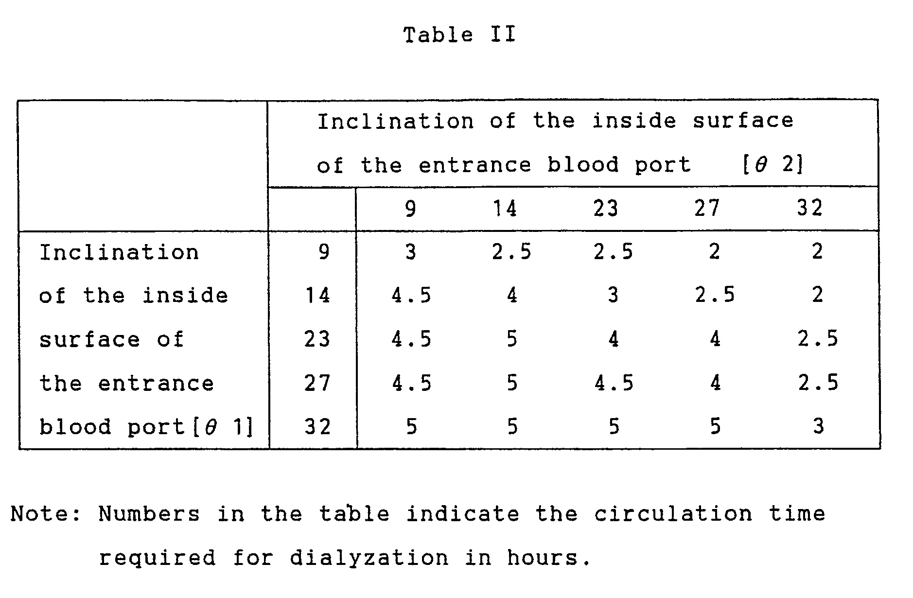
- Although, the liquid processing apparatus of the present invention is described above in terms of artificial dialyzers in which the present invention is embodied, the present invention can be utilized to a lung machine, blood plasma separator, and other applications.
- The hollow fiber type blood processing apparatus of the present invention comprises a housing, a bundle of hollow fibers which consists of a great number of hollow fibers for processing blood and is housed in the housing, an inlet and an outlet of a blood processing liquid which are provided near each end of the housing, partitions which secure each end of the bundle of hollow fibers to each end of the housing, an entrance blood port which has a blood inlet and is attached to one end of the housing, and an exit blood port which has a blood outlet and is attached to the other end of the housing, wherein the two blood ports have each an annular groove at the peripheral area of their inside surface and an annular elastic member conjoined in the annular groove by molding, the annular elastic members have each an annular elastic rib extended out of the annular groove, and the blood ports are attached to the housing with their annular elastic member pressed to the corresponding partition and the annular elastic rib of the annular elastic member pinched between the partition and the annular rib which defines the radially inner side of the annular groove of each blood port. By this construction, the annular elastic members are deformed and pinched between each partition and the annular rib of each blood port. Therefore, it is made possible to seal securely the partitions and the blood ports without o-rings. Moreover, the gap space between the annular rib and the partition is reduced and thereby blood clot formation due to the stagnation of blood within this space can be prevented.
- Further, the hollow fiber type liquid processing apparatus of the present invention comprises the housing, a bundle of hollow fibers which consists of a great number of hollow fibers for processing blood and is housed in the housing, an inlet and an outlet for a blood processing liquid which are provided near each ends of the housing, partitions which secure each end of the bundle of hollow fibers to each end of the housing, an entrance blood port which has a blood inlet and is attached to one end of the housing, and an exit blood port which has a blood outlet and is attached to the other end of the housing, wherein the two blood ports have each an annular groove at the peripheral area of their inside surface and an annular elastic member secured in each annular groove, and an annular hollow space formed between the annular elastic member and the annular rib which defines the radially-inner side of the annular groove in the inside surface of each blood port and the blood ports are attached to the housing with their annular elastic member pressed to the corresponding partition. By this construction, burrs grow along the side of the annular elastic member within the annular hollow space when the annular elastic member is first molded and then the blood port is injection molded, while burrs grow along the bottom side of the annular hollow space when the blood port is first mold and then the annular elastic member is injection molded. These burrs are buried under the deformed annular elastic members when the blood ports are attached to the housing. Consequently, it is made possible to eliminate blood-clot formation due to contact with the burrs and to prevent a fine pieces of broken burr from entering the blood and flowing into the human body.
- Furthermore, the hollow fiber type liquid processing apparatus of the present invention comprises the housing, a bundle of hollow fibers which consists of a great number of hollow fibers for processing blood and is housed in the housing, an inlet and an outlet for a blood processing liquid which are provided near each ends of the housing, partitions which secure each end of the bundle of hollow fibers to each end of the housing, an entrance blood port which has a blood inlet and is attached to one end of the housing, and an exit blood port which has a blood outlet and is attached to the other end of the housing, wherein the entrance blood port and the exit blood port have different inside shape from each other. By this construction, the blood stream inside the blood ports becomes smooth and the blood is distributed equally to all the hollow tubes so that the processing capability of the apparatus is increased while occurrence of blood coagulation is reduced.
- When the ratio of the inclination of the inside surface of the
exit blood port 71ϑ 1 to that of theentrance blood port 70ϑ 2 is 1.1 to 3.0, occurrence of blood coagulation is substantially reduced.
Claims (20)
- A hollow fiber type blood processing apparatus comprising:
a housing;
a bundle of hollow fibers which consists of a great number of hollow fibers for processing blood and is housed in the housing;
an inlet and an outlet of a blood processing liquid which are provided near each end of the housing;
partitions which secure each end of the bundle of hollow fibers to each end of the housing;
an entrance blood port which has a blood inlet and is attached to one end of the housing; and
an exit blood port which has a blood outlet and is attached to the other end of the housing: and
characterized in that the entrance blood port and the exit blood port have each an annular groove at the peripheral area of their inside surface and an annular elastic member conjoined in the annular groove by molding, the annular elastic members have each an annular elastic rib extended out of the annular groove, and
the entrance blood port and the exit blood port are attached to the housing with their annular elastic member pressed to the corresponding partition and the annular elastic rib of the annular elastic member pinched between the partition and an annular rib of the blood port which defines the radially inner side of the annular groove of each blood port. - A hollow fiber type blood processing apparatus in claim 1, wherein said annular elastic rib extends from the radially-inner portion of the annular elastic member and the radially-outer side of the annular elastic rib becomes smaller in diameter toward the top so that the cross section of the annular elastic rib becomes thinner toward the top end.
- A hollow fiber type blood processing apparatus in claim 1, wherein said annular elastic rib comprises a first annular elastic rib which extends from the radially-inner portion of the annular elastic member and is pinched between the partition and the annular rib of the blood port defining the radially-inner side of the annular groove and a second annular elastic rib which extends from the radially-outer portion of the annular elastic member and is pinched between the partition and the shoulder portion of the blood port defining the radially-outer side of the annular groove.
- A hollow fiber type blood processing apparatus in claim 3, wherein the radially-inner side of said second annular elastic rib becomes greater in diameter toward the top so that the cross section of the second annular elastic rib becomes thinner toward the top.
- A hollow fiber type blood processing apparatus in claim 1, wherein said annular elastic rib of said annular elastic member is pressed to the peripheral area of said partition with no hollow fiber ends secured.
- A hollow fiber type blood processing apparatus in claim 1, which is embodied into a hollow fiber type dialyzer.
- A hollow fiber type blood processing apparatus in claim 1, wherein said annular elastic member is conjoined to the blood port by two-color molding.
- A hollow fiber type blood processing apparatus comprising the housing;
a bundle of hollow fibers which consists of a great number of hollow fibers for processing blood and is housed in the housing;
an inlet and an outlet for a blood processing liquid which are provided near each ends of the housing;
partitions which secure each end of the bundle of hollow fibers to each end of the housing;
an entrance blood port which has a blood inlet and is attached to one end of the housing; and
an exit blood port which has a blood outlet and is attached to the other end of the housing: and characterized in that the entrance blood port and the exit blood port have each an annular groove at the peripheral area of their inside surface and an annular elastic member secured in each annular groove, and an annular hollow space formed between the annular elastic member and an annular rib which defines the radially-inner side of the annular groove in the inside surface of each blood port,
and the entrance blood port and the exit blood port are attached to the housing with their annular elastic member pressed to the corresponding partition. - A hollow fiber type blood processing apparatus in claim 8, wherein said annular elastic member is so deformed as to fill said annular hollow space.
- A hollow fiber type blood processing apparatus in claim 8, wherein said annular elastic member has an annular elastic rib extended out of said annular groove and the annular elastic rib is pinched between the partition and the annular rib of the blood port defining the radially-inner side of the annular groove.
- A hollow fiber type blood processing apparatus in claim 8, wherein said annular elastic rib extends from the radially-inner portion of the annular elastic member and the radially-outer side of the annular elastic rib becomes smaller in diameter toward the top so that the cross section of the annular elastic rib becomes thinner toward the top end.
- A hollow fiber type blood processing apparatus in claim 8, wherein said annular elastic rib comprises a first annular elastic rib which extends from the radially-inner portion of the annular elastic member and is pinched between the partition and the annular rib of the blood port defining the radially-inner side of the annular groove and a second annular elastic rib which extends from the radially-outer portion of the annular elastic member and is pinched between the partition and the shoulder portion of the blood port defining the radially-outer side of the annular groove.
- A hollow fiber type blood processing apparatus in claim 12, wherein the radially-inner side of said second annular elastic rib becomes greater in diameter toward the top so that the cross section of the second annular elastic rib becomes thinner toward the top.
- A hollow fiber type blood processing apparatus in claim 8, wherein said partitions have a peripheral area where no hollow fibers are secured and said annular elastic rib of said annular elastic member is pressed to the peripheral area of the corresponding partition.
- A hollow fiber type blood processing apparatus in claim 8, which is embodied into a hollow fiber type dialyzer.
- A hollow fiber type blood processing apparatus in claim 8, wherein said annular elastic member is conjoined to the blood port by two-color molding.
- A hollow fiber type blood processing apparatus comprising,
the housing;
a bundle of hollow fibers which consists of a great number of hollow fibers for processing blood and is housed in the housing;
an inlet and an outlet for a blood processing liquid which are provided near each ends of the housing;
partitions which secure each end of the bundle of hollow fibers to each end of the housing;
an entrance blood port which has a blood inlet and is attached to one end of the housing; and
an exit blood port which has a blood outlet and is attached to the other end of the housing: and
characterized in that the entrance blood port and the exit blood port have different inside shape. - A hollow fiber type blood processing apparatus in claim 17, wherein the inclination of the inside surface of the exit blood port ϑ 1 to that of the entrance blood port ϑ 2 is 1.1 to 3.0.
- A hollow fiber type blood processing apparatus in claim 17, wherein the inclination of the inside surface of the exit blood port ϑ 1 is 10° to 30°.
- A hollow fiber type blood processing apparatus in claim 17 which is embodied into a hollow fiber type dialyzer.
Applications Claiming Priority (4)
| Application Number | Priority Date | Filing Date | Title |
|---|---|---|---|
| JP10246490A JPH084620B2 (en) | 1990-04-18 | 1990-04-18 | Hollow fiber membrane blood treatment device |
| JP102464/90 | 1990-04-18 | ||
| JP103944/90 | 1990-04-19 | ||
| JP2103944A JP2517777B2 (en) | 1990-04-19 | 1990-04-19 | Hollow fiber membrane blood treatment device |
Publications (2)
| Publication Number | Publication Date |
|---|---|
| EP0452902A2 true EP0452902A2 (en) | 1991-10-23 |
| EP0452902A3 EP0452902A3 (en) | 1992-02-26 |
Family
ID=26443188
Family Applications (1)
| Application Number | Title | Priority Date | Filing Date |
|---|---|---|---|
| EP19910106135 Ceased EP0452902A3 (en) | 1990-04-18 | 1991-04-17 | Hollow fiber type liquid processing apparatus |
Country Status (3)
| Country | Link |
|---|---|
| US (1) | US5160615A (en) |
| EP (1) | EP0452902A3 (en) |
| AU (1) | AU635414B2 (en) |
Cited By (3)
| Publication number | Priority date | Publication date | Assignee | Title |
|---|---|---|---|---|
| EP0647464A3 (en) * | 1993-10-12 | 1996-03-06 | Koch Membrane Systems Inc | Spiral filtration module having bypass prevention flange. |
| EP1908509A1 (en) * | 2006-10-03 | 2008-04-09 | Sorin Group Italia S.r.l. | A process for producing exchange devices for medical use and exchange device produced thereby |
| EP2750785A4 (en) * | 2011-09-02 | 2015-11-25 | Nanoh2O Inc | SEAL PLATE FOR MEMBRANE SEPARATION DEVICE |
Families Citing this family (22)
| Publication number | Priority date | Publication date | Assignee | Title |
|---|---|---|---|---|
| US5270004A (en) | 1989-10-01 | 1993-12-14 | Minntech Corporation | Cylindrical blood heater/oxygenator |
| DE69305742T2 (en) * | 1992-05-18 | 1997-04-10 | Minntech Corp | HOLLOW FIBER FILTER CARTRIDGE AND METHOD FOR THE PRODUCTION THEREOF |
| US5328610A (en) * | 1993-06-15 | 1994-07-12 | Integrated Process Technologies | Self-supported low pressure drop hollow fiber membrane panel and contactor module |
| JP3396085B2 (en) * | 1994-05-24 | 2003-04-14 | テルモ株式会社 | Hollow fiber membrane type blood processor |
| US6378907B1 (en) | 1996-07-12 | 2002-04-30 | Mykrolis Corporation | Connector apparatus and system including connector apparatus |
| JP4773026B2 (en) * | 2000-03-10 | 2011-09-14 | スリーエム イノベイティブ プロパティズ カンパニー | Medical dressing having a plurality of adhesives and manufacturing method |
| JP4966475B2 (en) | 2000-05-12 | 2012-07-04 | ポール・コーポレーション | filter |
| DE60117260T2 (en) | 2000-05-12 | 2006-10-05 | Pall Corp. | FILTRATION SYSTEMS |
| US6846409B2 (en) | 2000-09-13 | 2005-01-25 | Mykrolis Corporation | Liquid filtration device |
| US20030075498A1 (en) * | 2001-06-01 | 2003-04-24 | Watkins Randolph H. | Hemodialyzer headers |
| US6623638B2 (en) | 2001-06-01 | 2003-09-23 | Baxter International Inc. | Hemodialyzer having improved dialysate perfusion |
| US6802821B2 (en) * | 2001-10-01 | 2004-10-12 | Fresenius Usa, Inc. | Dialyzer |
| US7163237B2 (en) | 2001-09-13 | 2007-01-16 | Entegris, Inc. | Separation module |
| US7469932B2 (en) | 2001-09-13 | 2008-12-30 | Entegris, Inc. | Receptor for a separation module |
| CA2481865C (en) * | 2003-09-24 | 2011-07-05 | Nipro Corporation | Hollow fiber blood-processing device and method for packaging and sterilizing such devices |
| DE102007043330A1 (en) * | 2007-09-12 | 2009-03-19 | Carl Freudenberg Kg | humidifier |
| CN102238997A (en) * | 2008-11-13 | 2011-11-09 | 白狐技术有限公司 | Method for sealing membrane modules |
| CZ303190B6 (en) * | 2011-07-22 | 2012-05-16 | Univerzita Karlova v Praze, Lékarská fakulta v Plzni | Heat exchanger with laminarizer |
| FR3011484B1 (en) * | 2013-10-09 | 2017-06-23 | Air Liquide | AIR SEPARATION DEVICE, INERTING DEVICE AND AIRCRAFT COMPRISING SUCH A DEVICE |
| JP2018507100A (en) * | 2015-01-06 | 2018-03-15 | ナノストーン ウォーター インコーポレイテッド | Membrane assembly with end cap device and related methods |
| HUE065846T2 (en) | 2016-06-16 | 2024-06-28 | Haemonetics Corp | Blood processing system with Y-connector |
| DE102021129241A1 (en) | 2021-11-10 | 2023-05-11 | B.Braun Avitum Ag | Sealing adapter with a contour sealing element for filter assembly adaptation for functional testing of hollow fiber filter modules |
Family Cites Families (19)
| Publication number | Priority date | Publication date | Assignee | Title |
|---|---|---|---|---|
| US2995057A (en) * | 1957-03-15 | 1961-08-08 | Parker Hannifin Corp | Seal for rigid seating members wherein protruding portion thereof is receivable into adjacent channel portion |
| DE1963319B1 (en) * | 1969-12-17 | 1970-12-03 | Bio Cal Instr Gmbh | Artificial lung |
| US3882024A (en) * | 1974-04-19 | 1975-05-06 | Dow Chemical Co | Header for stagnation-sensitive liquids |
| DE2646358C2 (en) * | 1976-10-14 | 1982-05-13 | Dr. Eduard Fresenius, Chemisch-pharmazeutische Industrie KG Apparatebau KG, 6380 Bad Homburg | Hollow fiber dialyzer |
| FR2374932A1 (en) * | 1976-12-24 | 1978-07-21 | Rhone Poulenc Ind | HOLLOW FIBER APPARATUS, USABLE IN PARTICULAR AS AN ARTIFICIAL KIDNEY |
| US4283284A (en) * | 1979-07-18 | 1981-08-11 | Baxter Travenol Laboratories, Inc. | Hollow fiber dialyzer end seal system |
| DE3144552A1 (en) * | 1981-11-10 | 1983-05-19 | Sigdell, Jan-Erik, Dr., 4052 Basel | Flow-adapted dialyser cover |
| DE3144553A1 (en) * | 1981-11-10 | 1983-05-19 | Jan-Erik Dr. 4052 Basel Sigdell | Flow-adapted dialyser cover |
| JPS59218161A (en) * | 1983-05-27 | 1984-12-08 | テルモ株式会社 | Hollow fiber membrane type artificial lung and production thereof |
| FR2553674B1 (en) * | 1983-10-21 | 1988-09-23 | Hospal Ind | SEMI-PERMEABLE HOLLOW FIBER APPARATUS IN WHICH AT LEAST IN A POTTING MASS A JOINT IS PROVIDED IN A THROAT |
| JPS6163240U (en) * | 1984-09-29 | 1986-04-28 | ||
| JPS61128978A (en) * | 1984-11-27 | 1986-06-17 | テルモ株式会社 | Membrane type artificial lung |
| US4688752A (en) * | 1986-04-25 | 1987-08-25 | Libbey-Owens-Ford Co. | Mold structure for producing an encapsulated window assembly |
| EP0264696A3 (en) * | 1986-10-13 | 1989-03-15 | Akzo N.V. | Mass exchange apparatus |
| DE3711695A1 (en) * | 1987-04-07 | 1988-10-27 | Akzo Gmbh | Distribution cap for a device for the extracorporal treatment of blood or its components |
| JPS645564A (en) * | 1987-06-29 | 1989-01-10 | Terumo Corp | Heat or mass exchange apparatus |
| US4980060A (en) * | 1987-07-13 | 1990-12-25 | Asahi Kasei Kogyo Kabushiki Kaisha | Hollow fiber membranes with fusion-bonded end portions |
| US4966699A (en) * | 1988-05-25 | 1990-10-30 | Terumo Kabushiki Kaisha | Hollow fiber membrane fluid processor |
| SE465095B (en) * | 1988-07-07 | 1991-07-22 | Gambro Dialysatoren | SEALING INCLUDING A RING OF A FLEXIBLE MATERIAL INTENDED TO BE PRESSED BETWEEN TWO PARALLEL, PRELIMINALLY SMALL SEALING SURFACES |
-
1991
- 1991-04-17 AU AU75070/91A patent/AU635414B2/en not_active Ceased
- 1991-04-17 EP EP19910106135 patent/EP0452902A3/en not_active Ceased
- 1991-04-18 US US07/687,718 patent/US5160615A/en not_active Expired - Lifetime
Cited By (3)
| Publication number | Priority date | Publication date | Assignee | Title |
|---|---|---|---|---|
| EP0647464A3 (en) * | 1993-10-12 | 1996-03-06 | Koch Membrane Systems Inc | Spiral filtration module having bypass prevention flange. |
| EP1908509A1 (en) * | 2006-10-03 | 2008-04-09 | Sorin Group Italia S.r.l. | A process for producing exchange devices for medical use and exchange device produced thereby |
| EP2750785A4 (en) * | 2011-09-02 | 2015-11-25 | Nanoh2O Inc | SEAL PLATE FOR MEMBRANE SEPARATION DEVICE |
Also Published As
| Publication number | Publication date |
|---|---|
| AU635414B2 (en) | 1993-03-18 |
| US5160615A (en) | 1992-11-03 |
| EP0452902A3 (en) | 1992-02-26 |
| AU7507091A (en) | 1991-12-19 |
Similar Documents
| Publication | Publication Date | Title |
|---|---|---|
| US5160615A (en) | Hollow fiber type liquid processing apparatus | |
| JP3396085B2 (en) | Hollow fiber membrane type blood processor | |
| EP0080661B1 (en) | Device for transfer of medical substance | |
| JP6162199B2 (en) | A set of easy-to-clean connectors for liquid circuits | |
| KR101118380B1 (en) | Degassing device and end cap assembly for filter comprising the degassing device | |
| EP0181470B1 (en) | Material transfer apparatus of hollow fiber type | |
| EP3765114B1 (en) | Multi-purpose cap for fluid ports on a medical device | |
| US4615694A (en) | Vented cone filter | |
| EP0046583B1 (en) | Hollow fiber-type artificial lung having enclosed heat exchanger | |
| JP2887347B2 (en) | Diffusion / filtration apparatus and method for manufacturing the same | |
| JP3254222B2 (en) | Hollow fiber device and manufacturing method thereof | |
| US5058661A (en) | Heat exchanger with leakage collector | |
| JPS5940481B2 (en) | Header for liquids sensitive to stagnation | |
| JPS58112549A (en) | Fluid filter | |
| JP2000210539A (en) | Body fluid treatment device, hollow fiber membrane assembly and production of body fluid treatment device | |
| US4617161A (en) | Method of manufacture for a dialyzer having improved side ports | |
| JPH0119903B2 (en) | ||
| EP0247213A1 (en) | Filter for eliminating air | |
| JP4807912B2 (en) | Hollow fiber membrane module and manufacturing method thereof | |
| JPH10165777A (en) | Hollow yarn module and its production | |
| JP2517777B2 (en) | Hollow fiber membrane blood treatment device | |
| JPH069671Y2 (en) | Hollow fiber type body fluid treatment device | |
| JPH084620B2 (en) | Hollow fiber membrane blood treatment device | |
| CN221084313U (en) | Dialyser | |
| JP4356534B2 (en) | Coupler joint for dialyzer connection |
Legal Events
| Date | Code | Title | Description |
|---|---|---|---|
| PUAI | Public reference made under article 153(3) epc to a published international application that has entered the european phase |
Free format text: ORIGINAL CODE: 0009012 |
|
| 17P | Request for examination filed |
Effective date: 19910417 |
|
| AK | Designated contracting states |
Kind code of ref document: A2 Designated state(s): BE DE FR GB IT NL SE |
|
| PUAL | Search report despatched |
Free format text: ORIGINAL CODE: 0009013 |
|
| AK | Designated contracting states |
Kind code of ref document: A3 Designated state(s): BE DE FR GB IT NL SE |
|
| 17Q | First examination report despatched |
Effective date: 19931021 |
|
| STAA | Information on the status of an ep patent application or granted ep patent |
Free format text: STATUS: THE APPLICATION HAS BEEN REFUSED |
|
| 18R | Application refused |
Effective date: 19960524 |