EP0452800A1 - Device for verifying the correct employment of the yarns used in a textile machine, in particular a knitting or hosiery machine - Google Patents
Device for verifying the correct employment of the yarns used in a textile machine, in particular a knitting or hosiery machine Download PDFInfo
- Publication number
- EP0452800A1 EP0452800A1 EP19910105730 EP91105730A EP0452800A1 EP 0452800 A1 EP0452800 A1 EP 0452800A1 EP 19910105730 EP19910105730 EP 19910105730 EP 91105730 A EP91105730 A EP 91105730A EP 0452800 A1 EP0452800 A1 EP 0452800A1
- Authority
- EP
- European Patent Office
- Prior art keywords
- cycle
- yarn
- error
- machine
- master
- Prior art date
- Legal status (The legal status is an assumption and is not a legal conclusion. Google has not performed a legal analysis and makes no representation as to the accuracy of the status listed.)
- Granted
Links
Images


Classifications
-
- D—TEXTILES; PAPER
- D04—BRAIDING; LACE-MAKING; KNITTING; TRIMMINGS; NON-WOVEN FABRICS
- D04B—KNITTING
- D04B15/00—Details of, or auxiliary devices incorporated in, weft knitting machines, restricted to machines of this kind
- D04B15/94—Driving-gear not otherwise provided for
- D04B15/99—Driving-gear not otherwise provided for electrically controlled
-
- D—TEXTILES; PAPER
- D04—BRAIDING; LACE-MAKING; KNITTING; TRIMMINGS; NON-WOVEN FABRICS
- D04B—KNITTING
- D04B35/00—Details of, or auxiliary devices incorporated in, knitting machines, not otherwise provided for
- D04B35/10—Indicating, warning, or safety devices, e.g. stop motions
- D04B35/12—Indicating, warning, or safety devices, e.g. stop motions responsive to thread consumption
Abstract
Description
- This invention relates to a device for verifying the correct employment of the yarns used by a textile machine, in particular a knitting or hosiery machine.
- These machines manufacture fabric composed of differently used sequences of the available yarns. At each moment of operation of the machine a sub-group of the total group of yarns present is therefore being used.
- The high machine working speed means that the fabric or article can be inspected only when completed. At this point the operator visually checks whether the article produced corresponds to the master, and if this is not the case that article and those produced subsequently up to the end of the checking procedure have to be discarded.
- A visual check can obviously be unprecise, allowing errors to slip through with serious repercussion on the subsequent operating stages.
- For example, it is very difficult to determine by sight whether the article produced is slightly longer or shorter than the master article, or whether a certain yarn has been used for too many or too few cycles.
- In the hosiery field this means that on termination of production, personnel have to be provided to correctly pair the various items produced.
- A computer-controlled machine is already known which senses and memorises by means of sensors whether and when the various yarns are used for a given production on the textile machine, and then subsequently uses the reference information obtained during this stage, known as the learning stage, for controlling the subsequent production via a comparison operation.
- This machine has certain drawbacks, one of which is that it does not provide adequate handling of the errors. It simply accumulates then in a counter, and when this counter reaches a predetermined threshold the machine is set into the error state.
- Thus the machine is set into the error state only by a series of errors detected for different yarns, whereas these errors if considered individually, ie in relation to each individual yarn, could well be negligible.
- A further drawback is that the known control device sets the textile machine into the error state and halts it only on termination of production of the master or article. This could result in serious breakage or malfunction of the textile machine, due for example to the impact of needles against fixed parts, because the textile machine continues to operate even if the yarn employment is in error.
- A further drawback is that the device does not indicate an out-of-phase state, ie that the article production stage is for various reasons longer or shorter than the master production stage, ie the optimum, so resulting for example in stockings longer or shorter than normal and which have then to be properly paired, this not being always easy to do.
- A further drawback is that the device does not enable the textile machine to be used to produce articles involving several operating stages (such as pantie hose) as it considers the basic operating stage of the textile machine to be the only possible stage, and does not allow further stages. Neither can the device be used for producing articles which do not have a proper end or a proper beginning, such as tablecloths and the like.
- The final drawback is that the device does not measure the yarn feed velocity, and thus when working terry cloth or vanise it visualizes correct operation even when certain of these yarns are not used to produce the loop but to produce the reference weft for example of the stocking.
- An object of the invention is to memorize the exact number of revolutions of the textile machine drive shaft or a multiple thereof undergone during a learning cycle, in order to detect a possible machine fault or error which has caused a variation in the duration of an operating cycle, or a mistake in the setting of the production cycle by the operator on starting a new production.
- A further object is to provide precise information on the type of error which the machine has committed, or whether the yarn has not been taken up by the machine or has been taken up in error, the number of interventions for each yarn and for each type of error, and whether the machine is out of phase.
- A further object is to monitor not only the movement or lack of movement of the yarn fed to the textile machine but also the velocity with which these yarns are fed during the learning stage, to be able to indicate any abnormality deriving from an excessive difference between the yarn feed velocity and that memorized.
- A further object is to provide more appropriate handling of the error by instantaneously halting the machine (even if it has not reached the end of the cycle) when the same type of error has been sensed by the same sensor a predetermined number of times.
- A further object is to provide an approximate measurement in terms of percentage of yarn utilization, to thus provide the user (by associating said percentages with correction constants based on the type of yarn and the type of knitting produced) with the true percentages of each yarn used during operation, so avoiding the traditional weighing of the yarn bobbins before and after the master production cycle to determine the amount of yarn used.
- These and further objects which will be apparent from the description given hereinafter are attained according to the present invention by a device for textile machines in accordance with the accompanying claims.
- The present invention will be more apparent from the description given hereinafter by way of non-limiting embodiment with reference to the accompanying drawings in which:
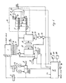
- Figure 1 is an overall block diagram of a textile machine with its controls;
- Figure 2 is a flow diagram showing the steps necessary for memorizing the master article;
- Figure 3 is a flow diagram showing the steps necessary for controlling the subsequent articles.
- With reference to said figures, a time reference signal is obtained from a proximity sensor B located on the drive shaft of a textile machine 1 and a cycle commencement and termination signal is obtained from a switch A located on the cylinder of the textile machine, which is of circular type.
- The cycle commencement and termination signal enters a
divider 2 which enables the total control cycle to be computed within one or more textile machine cycles, and the time reference signal enters a divider 3 to allow correct synchronization of the control device at the textile machine. The output of the divider 3 operates as a timer pulse CK for the control device. - The output signal from the divider 3 is fed in turn by a changeover switch to two
counters - These components represent that part of the device concerned with checking the cycle length.
-
Sensors 10 are positioned at the feed yarns F to the textile machine 1 to both sense the movement and measure the velocity of each individual yarn. For simplicity eight sensors are shown, but their number depends on the number of yarns used in the textile machine. Thesensors 10 communicate their data to a buffer register 11 which in cooperation with the textilemachine control unit 12 andaddress registers 13, 13' enables the data obtained by said sensors to be stored in amemory 14 relative to the yarn state (at rest or in movement) and in amemory 15 relative to the yarn velocity. - For example, each bit of the
state memory 14 represents the state of movement of the yarn, ie whether said yarn is moving or whether the yarn F of any of the eightsensors 10 at a precise and definite moment in time is interrupted by timing pulses as described hereinafter, whereas a byte of thevelocity memory 5 represents the yarn velocity determined by each individual sensor. - The
state memory 14 and the buffer register 11 are connected to acircuit 16 for detecting errors in the form of a broken or incorrectly used yarn. The purpose of this circuit is to indicate if the detected error has been sensed as having occurred several times by thesame sensor 10, and in such a case to indicate a "yarn error". - Said
circuit 16 consists of twoshift registers 17', 17 which serialize the data received from thememory 14 and from the buffer 11. The length of these registers is chosen on the basis of the number of errors to be detected and the number of sensors present. - Said registers are provided with intermediate outputs to enable the value of the bits present to be checked. For example these outputs are positioned at the bits corresponding to multiples of the number of sensors present.
- Each
shift register 17, 17' serially memorizes four successive sensor states, ie three already determined states plus the current state are present in oneshift register 17, while in the other 17' the four corresponding states determined during the master cycle and memorized in thestate memory 14 are present. - Coincidence circuits (for example exclusive OR) 19 compare the value of the output bits of the two
registers 17, 17'. In this manner they determine whether four states relative to a particular sensor differ from the four states stored in thestate memory 14, and thus indicate if there are four consecutive errors. To the same outputs of one shift register (for example 17) there are connected ANDcircuits 20 in series with anOR circuit 21 to indicate whether these errors are of the same type, for example whether there are four zeros in a row indicating four yarn breakage errors, or four ones in a row indicating four yarn erroneously used errors. - The outputs of the four
exclusive ORs 19 and of theOR 21 are connected to a total AND 22 which indicates the presence of errors of the same type at the same sensor. The register shift is suitably controlled by thecontrol unit 12. - The yarn velocity is measured for example on the basis that the
sensors 10 in addition to indicating the yarn state also provide a pulse frequency proportional to the velocity of each yarn. This frequency is measured by the buffer register 11 (or simply buffer) and stored in acounter 18, the value of which is then stored in thevelocity memory 15. Thevelocity memory 15 is controlled by acomparator 27 which compares the value in thecounter 18 with the value stored in thevelocity memory 15; thecomparator 27 indicates a velocity error if the compared values differ by more than a value stored in thelimit register 30. - The part which calculates the quantity of yarn used consists of a
multiplexer 23, acounter 24 and ausual computing unit 25. The multiplexer allows selection of which bit and therefore which yarn is to be considered. This multiplexer is connected to thestate memory 14, which is suitably scanned by theaddress register 13, the number of "one" bits found during this scanning being memorized in thecounter 24. Said counter is connected to acomputing unit 25 which using the data stored in thememory 15 also provides data relating to the percentage of yarn used and the total quantity of yarn used. - The
control unit 12 receives at its input all the signals required for the correct operation of the machine 1 (timer, end-of-cycle signal, reset signal etc.) originating from thedivider 2, from the comparator 7, from theAND gate 22, from theunit 25 and from thecomparator 27. Theunit 12 also generally handles the signals required for correct operation of the device comprising the members described up to this point (divider 2,sensors 10,memories logic gates unit 12 is also able to operate on a reception and transmission signal (RX and TX in Figure 1) which enables information to be fed to and be received from an external computer (not shown) so that thevelocity memory 15 andstate memory 14 can be stored permanently on a magnetic memory and then reloaded subsequently from this memory, to thus avoid the need to repeat self-learning cycles. - With reference to Figure 2, after initialization the device waits for the machine to supply a cycle commencement and termination signal. It then enables the choice to be made whether to memorize a master cycle or to control a working cycle.
- If the master cycle memorization is chosen, for each timing pulse the sensors are read together with their frequency. Information is then fed into the
state memory 14 and into thevelocity memory 15 until a further cycle commencement and termination signal is sensed, indicating that the first cycle has ended. - Data acquisition is achieved in the following manner: on arrival of the timing pulse CK, the data fed by the
various sensors 10 into the buffer 11 are read and its content fed to thestate memory 14. Thecounter 18 is then zeroed and the frequency which eachsensor 10 generates is read, ie the value which thecounter 18 memorizes after a predetermined time interval. This value is finally fed into thevelocity memory 15, suitably incrementing the address of the address registers 13'. - When the state and frequency have been memorized for all sensors present, a check is made to determine whether the acquisition cycle has terminated. If it has not, a further timing pulse CK is awaited to determine the new signals supplied by the sensors. In the meantime for each timing pulse the
reference counter 5 is incremented by one. On termination of the acquisition cycle the two memories contain data representing a digital "image" of the fabric produced, this image being composed of the state of the sensors and the velocity measured by them. In addition, thereference counter 5 contains the number of timing pulses required for an entire machine cycle. - On termination of the acquisition, either a new master cycle can be acquired or the next operation controlled.
- With reference to Figure 3, on choosing to control the next operation the extent of acceptable errors must firstly be keyed in, ie the acceptable cycle length error compared with the master cycle in the limit register 8, the maximum acceptable velocity error compared with the yarn velocity in the
limit register 30, and the number of errors of the same type at the same sensor to be allowed before indicating a total error. - The
control unit 12 then sets the two address registers 13, 13' of thememories sensors 10 is read in theshift register 17, while the addressedmaster state 13 is fed to 17', in which three previous states are already stored, as stated. The exclusive ORcircuits 19 check whether four errors are present between the two states, while the ANDgate 20 andOR gate 21 determine whether these errors are of the same type. - Signals are then fed from the OR
gates 19 andOR gate 21 to the ANDgate 22, which at its output provides an error signal only if an error of the same type generated by the same sensor had been detected. - This error signal is fed to the
control unit 12 which instantly (rather than at the end of the cycle) halts the machine and operates an alarm via astop signal 100. Thecontrol unit 12 also displays on adisplay unit 200 the type of error and the sensor involved by suitably investigating the support circuits not registered in theshift register 17, 17'. - If a state error has not been detected, at this point the
control unit 12 determines whether a velocity error has been provided by thecomparator 27 which checks whether the number indicating the velocity of the sensor addressed by the address register 13' is equal to that memorized by thecounter 18 by less than the value in thelimit register 30. - If there is no velocity error present the address registers 13, 13' are set to the commencement of samples obtained at the next timing pulse during the learning state, after which the
control unit 12 checks via the comparator F and the connected circuits whether a first out-of-phase error exists, evaluating if the pulses determined by the sensor B exceed a maximum acceptable value plus the set phase error value. If this is not the case, thecontrol unit 12 acquires further data if a cycle has terminated, or repeats its yarn state analysis on receiving pulses from the sensor B. - If an end-of-cycle pulse has been received, a second out-of-phase error check is made by evaluating if the pulses received from the sensor B are less than a maximum acceptable value less the set phase error.
- If a phase error is detected, the
control unit 12 indicates the type of error and halts the machine. - With the machine halted, the
control unit 12 waits for theappropriate pushbutton 300 present on thekeyboard 301 to be pushed, to enable it to start again from the beginning. - If errors are found, the unit checks whether the machine operator has selected a so-called reset cycle to enable the machine to commence a new cycle and abandon the old. In this case the state and velocity errors must not be taken into account. The
control unit 12 does this by suitably disenabling the output from thecomparator 27 and ANDcircuit 22, to prevent the error signal generated by them from further shutting down the machine during this reset cycle. - In a modified embodiment the circuit for detecting the
state error 16 can also consist of counters (two for each yarn) which memorize consecutive broken yarn or erroneously used yarn errors. These counters generate the error state signal when their value exceeds a predefined value. - The counter is incremented only if an error of its type is present, whereas it is again zeroed if at that moment of time there is no error relating to its type and its sensor.
- As can be seen from the flow diagrams relating to the operation of the device (Figures 2, 3), part of the device can be in the form of either hardware or software. For example the phase checking circuit and the error checking circuit can be formed totally with software, the choice depending entirely on the design.
Claims (15)
- A device for verifying the correct employment of the yarns used by textile machines (1), particularly circular machines, said machines being provided with means (10) for monitoring the movement of the yarns used for forming the fabric, means (A) for sensing the commencement of the textile machine cycle in producing a fabric article, means (B) for measuring the operational velocity of the textile machine, means (14, 15) for memorizing the information regarding yarn movements obtained during the production of a master fabric, comparator means (16, 27) for comparing the yarn movements during the production of fabrics subsequent to the master fabric, means (17, 17', 22) for detecting any error between the yarn movements relating to the master fabric and the subsequent movements, and means for halting the machine (1), characterised by comprising means for memorizing the length of the master cycle (2, 5, 6) and means for determining any error in the cycles (7, 9) subsequent to the master cycle in terms of duration difference between the former and the latter.
- A device as claimed in claim 1, characterised in that the means (10) for monitoring the movement of the yarns used for producing the fabric are means which determine whether the yarn is advancing or not, and the velocity at which it advances.
- A device as claimed in the preceding claims, characterised in that the comparator means comprise means (10, 18, 27) to evaluate both the state of the yarns and their velocity during the master cycle and during the current cycle.
- A device as claimed in claim 3, characterised in that the yarn velocity comparison means comprise at least one counter (18) and one comparator (27) having one input connected to the counter and the other connected to means (15) for memorizing information, said comparator providing an error signal if the two input values differ by more than a value preset in a limit register (30).
- A device as claimed in claim 3, characterised in that the means (16) for determining the yarn state error comprise means for detecting consecutive errors at the same sensor, means (20, 21) for determining whether said errors are of the same type, and means (22) for indicating a general error only if the two said means both provide an error indication.
- A device as claimed in the preceding claim, characterised in that the means for detecting consecutive errors are shift registers (17, 17') having intermediate outputs, and coincidence circuits (19) connected to said intermediate outputs.
- A device as claimed in claim 5, characterised in that the means for determining whether the consecutive errors are of the same type are comparison circuits, advantageously logic AND gates (20) with their inputs connected to the intermediate outputs of the shift registers (17, 17'), the outputs of which constitute the inputs to an OR circuit (21).
- A device as claimed in claim 1, characterised in that the means for memorizing the length of the master cycle comprise a counter (5) controlled by means (B) which indicate the velocity of the textile machine.
- A device as claimed in the preceding claim, characterised in that the means for determining the error in the cycle duration comprise a counter (6) and a comparator (7) which when the end-of-cycle pulse arrives compares the two counters (5, 6) and provides an error signal if the two differ by more than a value stored in the limit register (8).
- A device as claimed in claim 1, characterised in that the means for sensing the commencement and end of the cycle comprise divider means (2) which provide an end-of-cycle signal only after a predetermined number of cycle commencement and termination signals provided by the machine.
- A device as claimed in claim 1, characterised by further comprising means (23, 24, 25) for calculating the percentage utilization of each individual yarn in producing the master article.
- A device as claimed in the preceding claims, characterised by comprising means (23, 24, 25 and 15) for calculating the consumption of each individual yarn in producing the master article.
- A device as claimed in claim 12, characterised in that the means for calculating the percentage consumption of each individual yarn are a multiplexer (23), a counter (24) and a computing unit (25) which processes the data provided by the counter and the data present in the memory means to provide the desired values as output.
- A device as claimed in one or more of the preceding claims, characterised by comprising means for sensing a reset signal provided by the machine and means for disenabling machine error control when said signal is present.
- A device as claimed in one or more of the preceding claims, characterised in that the system control is by means of an integrated logic circuit (12), possibly program-operated, plus a keyboard (301) and a display unit (200).
Applications Claiming Priority (2)
| Application Number | Priority Date | Filing Date | Title |
|---|---|---|---|
| IT2008790 | 1990-04-20 | ||
| IT20087A IT1242051B (en) | 1990-04-20 | 1990-04-20 | REFERENCES CONCERNING THE CHECK OF THE CORRECT ABSORPTION OF THE THREADS USED IN A TEXTILE MACHINE, IN PARTICULAR FOR KNITWEAR OR FOOTWEAR |
Publications (2)
| Publication Number | Publication Date |
|---|---|
| EP0452800A1 true EP0452800A1 (en) | 1991-10-23 |
| EP0452800B1 EP0452800B1 (en) | 1996-01-10 |
Family
ID=11163696
Family Applications (1)
| Application Number | Title | Priority Date | Filing Date |
|---|---|---|---|
| EP91105730A Expired - Lifetime EP0452800B1 (en) | 1990-04-20 | 1991-04-11 | Device for verifying the correct employment of the yarns used in a textile machine, in particular a knitting or hosiery machine |
Country Status (6)
| Country | Link |
|---|---|
| US (1) | US5331564A (en) |
| EP (1) | EP0452800B1 (en) |
| AT (1) | ATE132921T1 (en) |
| DE (1) | DE69116204T2 (en) |
| ES (1) | ES2082878T3 (en) |
| IT (1) | IT1242051B (en) |
Cited By (8)
| Publication number | Priority date | Publication date | Assignee | Title |
|---|---|---|---|---|
| EP0489307A1 (en) * | 1990-12-04 | 1992-06-10 | INTERNATIONAL TRADING S.r.l. | Method and device for automatically controlling the quantity of yarn fed to a textile machine operating discontinuously thereon |
| EP0699792A1 (en) * | 1994-09-02 | 1996-03-06 | Shima Seiki Manufacturing, Ltd. | Methods of controlling yarn length in flat knitting machines and devices therefor |
| EP0752631A1 (en) * | 1995-07-03 | 1997-01-08 | B.T.S.R. INTERNATIONAL S.p.A. | Device for monitoring the feed of a plurality of yarns to a textile machine having encoded sensor means, and a method for its control |
| US5606875A (en) * | 1995-01-23 | 1997-03-04 | Shima Seiki Manufacturing Ltd. | Yarn length control system for a flat knitting machine |
| WO2004016843A1 (en) * | 2002-07-30 | 2004-02-26 | Memminger-Iro Gmbh | Method and device for delivering threads |
| US6832496B2 (en) | 2001-03-16 | 2004-12-21 | Memminger-Iro Gmbh | Method for monitoring/adjusting production in a knitting machine, and a monitoring/adjusting device therefor |
| EP2532776A1 (en) | 2011-06-08 | 2012-12-12 | SANTONI S.p.A. | A process for of adjusting the size of knitted articles under production in circular knitting machines for knitwear or hoisery |
| EP3098340A1 (en) * | 2015-05-20 | 2016-11-30 | L.G.L. Electronics S.p.A. | Method for reporting critical events on textile machines fed by a plurality of yarns |
Families Citing this family (5)
| Publication number | Priority date | Publication date | Assignee | Title |
|---|---|---|---|---|
| SE511091C2 (en) * | 1993-04-21 | 1999-08-02 | Sipra Patent Beteiligung | Yarn feeder for textile machines |
| EP0692562B1 (en) * | 1994-07-12 | 1999-09-15 | EAT Elektronische Ateliertechnik Textil GmbH | Method for realistically simulating a real fabric made of warp and weft yarns |
| AU7513996A (en) * | 1995-10-12 | 1997-04-30 | E.I. Du Pont De Nemours And Company | Process and apparatus for knitting fabric with non-elastic yarn and bare elastomeric yarn and sweater knit fabric construction |
| US6012405A (en) * | 1998-05-08 | 2000-01-11 | Mcet, Llc | Method and apparatus for automatic adjustment of thread tension |
| US6163733A (en) * | 1999-04-06 | 2000-12-19 | Rubel; Laurence P. | Monitor and malfunction predictor for textile machines |
Citations (5)
| Publication number | Priority date | Publication date | Assignee | Title |
|---|---|---|---|---|
| FR2421131A1 (en) * | 1978-03-30 | 1979-10-26 | Godier Roger | Electronic control device for textile machinery - controls delivery rollers, knives, cam systems, etc. |
| WO1984003906A1 (en) * | 1983-04-07 | 1984-10-11 | Iro Ab | Yarn-feeding apparatus and method for controlling it |
| US4744227A (en) * | 1987-06-23 | 1988-05-17 | Whitener Jr Charles G | Pattern monitoring method and apparatus |
| WO1988008048A1 (en) * | 1987-04-16 | 1988-10-20 | Aktiebolaget Iro | Monitoring system for knitting machines |
| DE3824034C1 (en) * | 1988-07-15 | 1989-09-14 | Gustav 7290 Freudenstadt De Memminger |
Family Cites Families (6)
| Publication number | Priority date | Publication date | Assignee | Title |
|---|---|---|---|---|
| GB8410640D0 (en) * | 1984-04-26 | 1984-05-31 | Iropa Textile Accessories | Positive feed |
| US4736324A (en) * | 1984-11-20 | 1988-04-05 | Tsudakoma Corp. | Centralized control method for loom and device thereof |
| GB2169928B (en) * | 1985-01-19 | 1988-05-11 | Rieter Scragg Ltd | Monitoring the tension of yarn drawn off from a package |
| US5136499A (en) * | 1986-07-07 | 1992-08-04 | Rydborn S A O | Monitoring for distinguishing normal from abnormal deviations in a knitting machine |
| US4835699A (en) * | 1987-03-23 | 1989-05-30 | Burlington Industries, Inc. | Automated distributed control system for a weaving mill |
| US5119308A (en) * | 1988-08-26 | 1992-06-02 | Murata Kikai Kabushiki Kaisha | Control system for spinning machine |
-
1990
- 1990-04-20 IT IT20087A patent/IT1242051B/en active IP Right Grant
-
1991
- 1991-04-11 DE DE69116204T patent/DE69116204T2/en not_active Expired - Lifetime
- 1991-04-11 ES ES91105730T patent/ES2082878T3/en not_active Expired - Lifetime
- 1991-04-11 AT AT91105730T patent/ATE132921T1/en not_active IP Right Cessation
- 1991-04-11 EP EP91105730A patent/EP0452800B1/en not_active Expired - Lifetime
- 1991-04-12 US US07/684,333 patent/US5331564A/en not_active Expired - Lifetime
Patent Citations (5)
| Publication number | Priority date | Publication date | Assignee | Title |
|---|---|---|---|---|
| FR2421131A1 (en) * | 1978-03-30 | 1979-10-26 | Godier Roger | Electronic control device for textile machinery - controls delivery rollers, knives, cam systems, etc. |
| WO1984003906A1 (en) * | 1983-04-07 | 1984-10-11 | Iro Ab | Yarn-feeding apparatus and method for controlling it |
| WO1988008048A1 (en) * | 1987-04-16 | 1988-10-20 | Aktiebolaget Iro | Monitoring system for knitting machines |
| US4744227A (en) * | 1987-06-23 | 1988-05-17 | Whitener Jr Charles G | Pattern monitoring method and apparatus |
| DE3824034C1 (en) * | 1988-07-15 | 1989-09-14 | Gustav 7290 Freudenstadt De Memminger |
Cited By (11)
| Publication number | Priority date | Publication date | Assignee | Title |
|---|---|---|---|---|
| EP0489307A1 (en) * | 1990-12-04 | 1992-06-10 | INTERNATIONAL TRADING S.r.l. | Method and device for automatically controlling the quantity of yarn fed to a textile machine operating discontinuously thereon |
| EP0699792A1 (en) * | 1994-09-02 | 1996-03-06 | Shima Seiki Manufacturing, Ltd. | Methods of controlling yarn length in flat knitting machines and devices therefor |
| US5606875A (en) * | 1995-01-23 | 1997-03-04 | Shima Seiki Manufacturing Ltd. | Yarn length control system for a flat knitting machine |
| EP0752631A1 (en) * | 1995-07-03 | 1997-01-08 | B.T.S.R. INTERNATIONAL S.p.A. | Device for monitoring the feed of a plurality of yarns to a textile machine having encoded sensor means, and a method for its control |
| US5838570A (en) * | 1995-07-03 | 1998-11-17 | B.T.S.R. International S.P.A. | Device for monitoring the feed of a plurality of yarns to a textile machine having encoded sensor means, and a method for its control |
| US6832496B2 (en) | 2001-03-16 | 2004-12-21 | Memminger-Iro Gmbh | Method for monitoring/adjusting production in a knitting machine, and a monitoring/adjusting device therefor |
| WO2004016843A1 (en) * | 2002-07-30 | 2004-02-26 | Memminger-Iro Gmbh | Method and device for delivering threads |
| US7303163B2 (en) | 2002-07-30 | 2007-12-04 | Memminger-Iro Gmbh | Method and system for delivering threads |
| EP2532776A1 (en) | 2011-06-08 | 2012-12-12 | SANTONI S.p.A. | A process for of adjusting the size of knitted articles under production in circular knitting machines for knitwear or hoisery |
| EP2985372A1 (en) | 2011-06-08 | 2016-02-17 | SANTONI S.p.A. | A process for regulating the size of knitted articles under production in circular knitting machines for knitwear or hosiery |
| EP3098340A1 (en) * | 2015-05-20 | 2016-11-30 | L.G.L. Electronics S.p.A. | Method for reporting critical events on textile machines fed by a plurality of yarns |
Also Published As
| Publication number | Publication date |
|---|---|
| EP0452800B1 (en) | 1996-01-10 |
| ATE132921T1 (en) | 1996-01-15 |
| DE69116204D1 (en) | 1996-02-22 |
| IT1242051B (en) | 1994-02-02 |
| ES2082878T3 (en) | 1996-04-01 |
| US5331564A (en) | 1994-07-19 |
| IT9020087A0 (en) | 1990-04-20 |
| DE69116204T2 (en) | 1996-05-23 |
| IT9020087A1 (en) | 1991-10-20 |
Similar Documents
| Publication | Publication Date | Title |
|---|---|---|
| US5331564A (en) | Device for verifying the correct employment of the yarns used in a textile machine, in particular a knitting or hosiery machine | |
| JP2556658B2 (en) | A method for detecting errors in textile webs. | |
| US3553728A (en) | Frequency measuring apparatus with automatic adjustment of measurement interval for enhanced speed and accuracy | |
| EP0487740A1 (en) | Method of monitoring operating conditions of injection molding machine | |
| US4744227A (en) | Pattern monitoring method and apparatus | |
| US6832496B2 (en) | Method for monitoring/adjusting production in a knitting machine, and a monitoring/adjusting device therefor | |
| US5225988A (en) | Device for controlling the operation of machines, particularly textile machines, able to self-learn the operating cycle of these latter and to correct its own errors during this self-learning stage | |
| US3792460A (en) | Shaft speed monitoring circuit | |
| US3877210A (en) | System for measuring the count and twist of spun yarn in open-end spinning | |
| EP1335054A2 (en) | Method and device for measuring weft thread, particularly in electronic circular knitting machines | |
| JPH03155915A (en) | Method of discriminating good and defective article in injection molding machine | |
| US4019310A (en) | Apparatus for digitally monitoring operating parameters of an open-end spinning machine | |
| US4817381A (en) | Process and apparatus for registering dead spinning or twisting stations | |
| US3456187A (en) | Thread speed measuring apparatus | |
| US3626725A (en) | Runner checker apparatus for warp knitting machines | |
| US5003668A (en) | Textile spinning machine | |
| JP3146435B2 (en) | Monitoring method and monitoring device | |
| EP2440698A2 (en) | Method and device for automatically measuring the yarn length fed to a rectilinear machine | |
| US4549268A (en) | Apparatus for measuring the length of filamentary material, such as yarn or thread wound-up at individual winding or spinning locations of a textile machine | |
| US4035618A (en) | Monitor for knitting machines | |
| KR100486093B1 (en) | Apparatus and Method for measuring stitch length | |
| GB1360154A (en) | Runner checker apparatus for warp knitting machines | |
| CN107620154A (en) | Method for controlling yarn to be unwind from weft yarn fournisseur | |
| SE462757B (en) | MONITORING SYSTEM FOR KNITTING MACHINERY | |
| US3968663A (en) | Knitting machine tension control |
Legal Events
| Date | Code | Title | Description |
|---|---|---|---|
| PUAI | Public reference made under article 153(3) epc to a published international application that has entered the european phase |
Free format text: ORIGINAL CODE: 0009012 |
|
| AK | Designated contracting states |
Kind code of ref document: A1 Designated state(s): AT BE CH DE DK ES FR GB IT LI LU NL SE |
|
| 17P | Request for examination filed |
Effective date: 19920217 |
|
| RIN1 | Information on inventor provided before grant (corrected) |
Inventor name: BAREA, TIZIANO |
|
| RAP1 | Party data changed (applicant data changed or rights of an application transferred) |
Owner name: INTERNATIONAL TRADING S.R.L. |
|
| 17Q | First examination report despatched |
Effective date: 19940323 |
|
| RAP1 | Party data changed (applicant data changed or rights of an application transferred) |
Owner name: B.T.S.R. INTERNATIONAL S.P.A. |
|
| GRAA | (expected) grant |
Free format text: ORIGINAL CODE: 0009210 |
|
| AK | Designated contracting states |
Kind code of ref document: B1 Designated state(s): AT BE CH DE DK ES FR GB IT LI LU NL SE |
|
| PG25 | Lapsed in a contracting state [announced via postgrant information from national office to epo] |
Ref country code: DK Effective date: 19960110 Ref country code: NL Free format text: LAPSE BECAUSE OF FAILURE TO SUBMIT A TRANSLATION OF THE DESCRIPTION OR TO PAY THE FEE WITHIN THE PRESCRIBED TIME-LIMIT Effective date: 19960110 |
|
| REF | Corresponds to: |
Ref document number: 132921 Country of ref document: AT Date of ref document: 19960115 Kind code of ref document: T |
|
| ITF | It: translation for a ep patent filed |
Owner name: ING. A. GIAMBROCONO & C. S.R.L. |
|
| REF | Corresponds to: |
Ref document number: 69116204 Country of ref document: DE Date of ref document: 19960222 |
|
| ET | Fr: translation filed | ||
| REG | Reference to a national code |
Ref country code: ES Ref legal event code: FG2A Ref document number: 2082878 Country of ref document: ES Kind code of ref document: T3 |
|
| PG25 | Lapsed in a contracting state [announced via postgrant information from national office to epo] |
Ref country code: LU Free format text: LAPSE BECAUSE OF NON-PAYMENT OF DUE FEES Effective date: 19960430 |
|
| NLV1 | Nl: lapsed or annulled due to failure to fulfill the requirements of art. 29p and 29m of the patents act | ||
| PLBE | No opposition filed within time limit |
Free format text: ORIGINAL CODE: 0009261 |
|
| STAA | Information on the status of an ep patent application or granted ep patent |
Free format text: STATUS: NO OPPOSITION FILED WITHIN TIME LIMIT |
|
| 26N | No opposition filed | ||
| REG | Reference to a national code |
Ref country code: GB Ref legal event code: IF02 |
|
| REG | Reference to a national code |
Ref country code: CH Ref legal event code: NV Representative=s name: R. A. EGLI & CO. PATENTANWAELTE |
|
| PGFP | Annual fee paid to national office [announced via postgrant information from national office to epo] |
Ref country code: IT Payment date: 20100326 Year of fee payment: 20 |
|
| PGFP | Annual fee paid to national office [announced via postgrant information from national office to epo] |
Ref country code: GB Payment date: 20100327 Year of fee payment: 20 |
|
| PGFP | Annual fee paid to national office [announced via postgrant information from national office to epo] |
Ref country code: ES Payment date: 20100412 Year of fee payment: 20 |
|
| PGFP | Annual fee paid to national office [announced via postgrant information from national office to epo] |
Ref country code: DE Payment date: 20100430 Year of fee payment: 20 Ref country code: AT Payment date: 20100406 Year of fee payment: 20 |
|
| PGFP | Annual fee paid to national office [announced via postgrant information from national office to epo] |
Ref country code: BE Payment date: 20100506 Year of fee payment: 20 Ref country code: CH Payment date: 20100727 Year of fee payment: 20 |
|
| PGFP | Annual fee paid to national office [announced via postgrant information from national office to epo] |
Ref country code: FR Payment date: 20100719 Year of fee payment: 20 Ref country code: SE Payment date: 20100423 Year of fee payment: 20 |
|
| REG | Reference to a national code |
Ref country code: DE Ref legal event code: R071 Ref document number: 69116204 Country of ref document: DE |
|
| REG | Reference to a national code |
Ref country code: CH Ref legal event code: PL |
|
| BE20 | Be: patent expired |
Owner name: *B.T.S.R. INTERNATIONAL S.P.A. Effective date: 20110411 |
|
| REG | Reference to a national code |
Ref country code: GB Ref legal event code: PE20 Expiry date: 20110410 |
|
| PG25 | Lapsed in a contracting state [announced via postgrant information from national office to epo] |
Ref country code: GB Free format text: LAPSE BECAUSE OF EXPIRATION OF PROTECTION Effective date: 20110410 |
|
| PG25 | Lapsed in a contracting state [announced via postgrant information from national office to epo] |
Ref country code: DE Free format text: LAPSE BECAUSE OF EXPIRATION OF PROTECTION Effective date: 20110411 |
|
| PG25 | Lapsed in a contracting state [announced via postgrant information from national office to epo] |
Ref country code: ES Free format text: LAPSE BECAUSE OF EXPIRATION OF PROTECTION Effective date: 20110412 |