EP0452778A2 - Pressure vacuum vessel and method of manufacture - Google Patents
Pressure vacuum vessel and method of manufacture Download PDFInfo
- Publication number
- EP0452778A2 EP0452778A2 EP91105628A EP91105628A EP0452778A2 EP 0452778 A2 EP0452778 A2 EP 0452778A2 EP 91105628 A EP91105628 A EP 91105628A EP 91105628 A EP91105628 A EP 91105628A EP 0452778 A2 EP0452778 A2 EP 0452778A2
- Authority
- EP
- European Patent Office
- Prior art keywords
- sheets
- vessel
- junctions
- walls
- joining
- Prior art date
- Legal status (The legal status is an assumption and is not a legal conclusion. Google has not performed a legal analysis and makes no representation as to the accuracy of the status listed.)
- Granted
Links
Images

Classifications
-
- B—PERFORMING OPERATIONS; TRANSPORTING
- B01—PHYSICAL OR CHEMICAL PROCESSES OR APPARATUS IN GENERAL
- B01J—CHEMICAL OR PHYSICAL PROCESSES, e.g. CATALYSIS OR COLLOID CHEMISTRY; THEIR RELEVANT APPARATUS
- B01J3/00—Processes of utilising sub-atmospheric or super-atmospheric pressure to effect chemical or physical change of matter; Apparatus therefor
- B01J3/006—Processes utilising sub-atmospheric pressure; Apparatus therefor
-
- F—MECHANICAL ENGINEERING; LIGHTING; HEATING; WEAPONS; BLASTING
- F16—ENGINEERING ELEMENTS AND UNITS; GENERAL MEASURES FOR PRODUCING AND MAINTAINING EFFECTIVE FUNCTIONING OF MACHINES OR INSTALLATIONS; THERMAL INSULATION IN GENERAL
- F16J—PISTONS; CYLINDERS; SEALINGS
- F16J12/00—Pressure vessels in general
-
- B—PERFORMING OPERATIONS; TRANSPORTING
- B01—PHYSICAL OR CHEMICAL PROCESSES OR APPARATUS IN GENERAL
- B01J—CHEMICAL OR PHYSICAL PROCESSES, e.g. CATALYSIS OR COLLOID CHEMISTRY; THEIR RELEVANT APPARATUS
- B01J3/00—Processes of utilising sub-atmospheric or super-atmospheric pressure to effect chemical or physical change of matter; Apparatus therefor
- B01J3/04—Pressure vessels, e.g. autoclaves
-
- C—CHEMISTRY; METALLURGY
- C23—COATING METALLIC MATERIAL; COATING MATERIAL WITH METALLIC MATERIAL; CHEMICAL SURFACE TREATMENT; DIFFUSION TREATMENT OF METALLIC MATERIAL; COATING BY VACUUM EVAPORATION, BY SPUTTERING, BY ION IMPLANTATION OR BY CHEMICAL VAPOUR DEPOSITION, IN GENERAL; INHIBITING CORROSION OF METALLIC MATERIAL OR INCRUSTATION IN GENERAL
- C23C—COATING METALLIC MATERIAL; COATING MATERIAL WITH METALLIC MATERIAL; SURFACE TREATMENT OF METALLIC MATERIAL BY DIFFUSION INTO THE SURFACE, BY CHEMICAL CONVERSION OR SUBSTITUTION; COATING BY VACUUM EVAPORATION, BY SPUTTERING, BY ION IMPLANTATION OR BY CHEMICAL VAPOUR DEPOSITION, IN GENERAL
- C23C14/00—Coating by vacuum evaporation, by sputtering or by ion implantation of the coating forming material
- C23C14/22—Coating by vacuum evaporation, by sputtering or by ion implantation of the coating forming material characterised by the process of coating
- C23C14/56—Apparatus specially adapted for continuous coating; Arrangements for maintaining the vacuum, e.g. vacuum locks
Definitions
- the present invention relates generally to leak-proof vessels, to such vessels which are subject to a pressure differential between the interior and the ambient and, in particular, to vacuum chambers used for processing semiconductors circuits.
- junction we use the terms "junction”, “three-weld junction” and “multiple-weld junction” interchangeably.
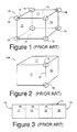
- FIG. 1 depicts an exemplary rectangular semiconductor vacuum vessel or chamber 10 that has been fabricated from sheet metal.
- the rectangular vessel 10 comprises four sidewalls 11, 12, 13 and 14 and top and bottom walls 16 and 17. If vessel 10 is assembled from six separate pieces of sheet metal, eight separate three-weld junctions 18 are formed, each of which is more susceptible to leaks than a weld between only two adjoining surfaces.
- the vessel 10A shown schematically in FIG. 2 to reduce the number of three-weld junctions, several of the walls can be formed from a single sheet.
- the four walls 11, 12, 13 and 14 can be bent from a single sheet 15 shown in FIG. 3 (sheet 15 is not to scale).
- This structure 10A requires simple two-edge welds along the top and bottom surfaces and along the end edges 19-19 and thus requires only two of the three-weld junctions 18-18, one each where the edges 19-19 are joined together and to the top and bottom walls.
- the vessel 10A would reduce the number of multiple-weld junctions vis-a-vis vessel 10, it would not eliminate them.
- the three bends are very difficult to make. Using regular bending machines, there would be no way to remove the closed structure which results from the three bends and, thus, special machines and techniques would be required.
- the above structure 10A does not eliminate the problem of fixing leaks at junctions. While any weld may leak, a continuous weld can be ground and rewelded, but it is almost impossible to grind and reweld a junction. Thus, it is usually necessary to discard rather than repair leaking vessels such as 10 and 10A. Such vessels, especially those used for applications such as semiconductor integrated circuit fabrication, are expensive and it is highly desirable to have a fabrication technique which is less subject to leaks and which can be repaired easily.
- my invention is embodied in a vessel which satisfies the above and other objects and comprises: a pair of mating sheets each formed in an open-ended arcuate configuration, such as a U-shaped configuration of three walls, for cooperatively fitting together along mating edges to form an enclosed chamber of polygonal cross-section, with the sheets fitting together without multiple edge junctions; and means for joining the sheets together along the junctions.
- the invention is applicable to both pressure and vacuum tanks.
- my present invention relates to the formation of pressure and vacuum tanks, is characterized by providing a vessel or tank which is devoid of multiple-edge junctions, and comprises forming each of a pair of sheets into an open-ended arcuate configuration, such as a U-shaped three wall configuration, adapted for mating with the other of the pair, so that the walls mate together without multiple edge junctions; and joining the sheets together along the junctions.
- the walls are preferably joined by welding.
- the sheets are U-shaped and each comprises three walls and all six walls defined by the two U-shaped sheets are of rectangular configuration.
- two of the opposite walls of one of the U-shaped sheets are non-rectangular polygons and the remaining walls are rectangular.
- the vessel 20 comprises a pair of mating sheets 21 and 25.
- Each sheet is bent or otherwise formed into an arcuate, open-ended configuration, illustratively a generally U-shaped configuration.
- exemplary sheet 21 comprises three walls 22, 23 and 24 (walls 22 and 24 form the legs of the U, while wall 23 forms the base), while sheet 25 comprises three walls 26, 27 and 28 (walls 26 and 28 form the legs of the U, while wall 27 forms the base).
- exemplary sheet 21 comprises three walls 22, 23 and 24 (walls 22 and 24 form the legs of the U, while wall 23 forms the base), while sheet 25 comprises three walls 26, 27 and 28 (walls 26 and 28 form the legs of the U, while wall 27 forms the base).
- the cooperatively formed, mating U-shaped members 21 and 25 are formed so that the walls (such as walls 22, 23 and 24 of member 21) enclose corresponding "open" spaces or openings between the walls of the other U-member (spaces 22', 23' and 24' of U-member 25).
- the two illustrated mating members 21 and 25 are U-shaped members which are rotated 90° relative to one another and are configured to enclose the open sides of one another.
- edge 51 of sheet 21 mates with edge 61 of sheet 25
- edges 52 and 62 form a second junction
- the corresponding edges 53/63, 54/64, 55/65, 56/66, 57/67 an 58/68 all form two-edge junctions.
- the weld seams 51/61...58/68 all are two-edge junctions.
- the welds are designated by the same numbers as the mating edges.
- the welding can be implemented as a continuous, single weld starting, for example, from edge 51/61 and wrapping around the vessel to and terminating at 58/68.
- FIGS. 4 and 5 also illustrate various types of apertures or holes which may be formed in the vessel sides to adapt the vessel to semiconductor fabrication or other use.
- apertures 31, 32 and 33 are fitted with a slit valve, a gate valve and a view port, respectively, and 34 is a mechanical feed-through.
- Other apertures provide access for process gas, mount pyrometers, pressure gauges, etc.
- the depicted apertures are shown by way of example only and are not limiting. Quite obviously, my vessel may be used in applications involving fewer or more apertures and associated fittings.
- my vessel is conveniently formed by bending or otherwise forming the U-shaped sheets 21 and 25 into their arcuate configuration, fitting the sheets together and then welding or otherwise joining the sheets along the mating, non-multiple-edge, junctions. Any apertures can be cut or stamped before the sheets are formed or joined or can be cut after the sheets are joined. Of course, any required valves, hardware, viewing ports, or other structural features or supports will be added as required by those of usual skill in the art.
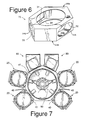
- FIG. 6 defines a second embodiment 70 of my vessel which incorporates all the features and advantages of the vessel 20.
- Vessel 70 differs from vessel 20 in that the two opposite sides 26A and 28A of the U-shaped sheet 25A comprise non-rectangular polygons while the mating sides 22A and 24A of the other U-shaped sheet 21A are bent or otherwise formed into the peripheral configuration of polygons 26A and 28A, to wrap around or wrap within the perimeter of polygon 26A and 28A.
- FIG. 7 depicts still another vessel configuration 80 which can be formed using my invention.
- each chamber 80 includes skewed six-sided top and bottom walls which accommodate the angled path of entry of robot 90 into the chamber.
- Semiconductor and other vacuum processing technology is moving toward automated, robotic, multiple chamber systems. It is desirable to minimize the footprint of such systems, that is, to configure the system such that the space occupied by the multiple processing chambers and the single or multiple loadlock chambers is as small as possible.
- My vessel design assists in achieving such design objectives because the non-joined edges (i.e., the bent edges 40, FIG. 3) can be formed as rounded edges.
- FIG. 7 there is shown a seven-sided loadlock or transfer chamber 41 having vessels 20 mounted on the walls thereof. The rounded adjacent edges on the vessels permit the vessels to be mounted closer together and permit the overall structure to be smaller than would be possible if square edges or sharp edges were used.
- the orientation of the chamber can be selected to maximize structural strength.
- the continuous seam 51/61 - 58/68 is especially suited for automated continuous welding, i.e., for joining by a single continuous weld.
Landscapes
- Chemical & Material Sciences (AREA)
- Engineering & Computer Science (AREA)
- General Engineering & Computer Science (AREA)
- Mechanical Engineering (AREA)
- Organic Chemistry (AREA)
- Chemical Kinetics & Catalysis (AREA)
- Materials Engineering (AREA)
- Metallurgy (AREA)
- Pressure Vessels And Lids Thereof (AREA)
- Welding Or Cutting Using Electron Beams (AREA)
- Butt Welding And Welding Of Specific Article (AREA)
- Drying Of Semiconductors (AREA)
Abstract
Description
- The present invention relates generally to leak-proof vessels, to such vessels which are subject to a pressure differential between the interior and the ambient and, in particular, to vacuum chambers used for processing semiconductors circuits.
- We use the terms "junction", "three-weld junction" and "multiple-weld junction" interchangeably.
- To my knowledge, there are available presently two feasible techniques for fabricating pressure or vacuum vessels such as the vacuum chambers which are used for processing semiconductor circuits: first, hogging or sculpting the vessel from a solid block of metal and, second, welding together appropriately patterned sheet metal. Of the two techniques, sheet metal fabrication typically requires less time and expense and is the presently preferred approach for fabricating such vessels.
- However, the use of sheet metal fabrication techniques requires the formation of multiple-weld junctions, which are susceptible of leakage, especially when tested after welding, and are nearly impossible to repair. This problem is illustrated in FIG. 1, which depicts an exemplary rectangular semiconductor vacuum vessel or
chamber 10 that has been fabricated from sheet metal. Therectangular vessel 10 comprises foursidewalls bottom walls vessel 10 is assembled from six separate pieces of sheet metal, eight separate three-weld junctions 18 are formed, each of which is more susceptible to leaks than a weld between only two adjoining surfaces. - Referring to the
vessel 10A shown schematically in FIG. 2, to reduce the number of three-weld junctions, several of the walls can be formed from a single sheet. For example, the fourwalls single sheet 15 shown in FIG. 3 (sheet 15 is not to scale). Thisstructure 10A requires simple two-edge welds along the top and bottom surfaces and along the end edges 19-19 and thus requires only two of the three-weld junctions 18-18, one each where the edges 19-19 are joined together and to the top and bottom walls. Thus, while thevessel 10A would reduce the number of multiple-weld junctions vis-a-visvessel 10, it would not eliminate them. Furthermore, the three bends are very difficult to make. Using regular bending machines, there would be no way to remove the closed structure which results from the three bends and, thus, special machines and techniques would be required. - In reducing the number of multiple-weld junctions, the
above structure 10A does not eliminate the problem of fixing leaks at junctions. While any weld may leak, a continuous weld can be ground and rewelded, but it is almost impossible to grind and reweld a junction. Thus, it is usually necessary to discard rather than repair leaking vessels such as 10 and 10A. Such vessels, especially those used for applications such as semiconductor integrated circuit fabrication, are expensive and it is highly desirable to have a fabrication technique which is less subject to leaks and which can be repaired easily. - In view of the above discussion, it is one object of the present invention to provide a method of fabricating vessels and a resulting vessel construction which do not employ multiple weld junctions.
- In one aspect, my invention is embodied in a vessel which satisfies the above and other objects and comprises: a pair of mating sheets each formed in an open-ended arcuate configuration, such as a U-shaped configuration of three walls, for cooperatively fitting together along mating edges to form an enclosed chamber of polygonal cross-section, with the sheets fitting together without multiple edge junctions; and means for joining the sheets together along the junctions. The invention is applicable to both pressure and vacuum tanks.
- In another aspect, my present invention relates to the formation of pressure and vacuum tanks, is characterized by providing a vessel or tank which is devoid of multiple-edge junctions, and comprises forming each of a pair of sheets into an open-ended arcuate configuration, such as a U-shaped three wall configuration, adapted for mating with the other of the pair, so that the walls mate together without multiple edge junctions; and joining the sheets together along the junctions.
- In another, more specific aspect, the walls are preferably joined by welding.
- In still another more specific aspect, the sheets are U-shaped and each comprises three walls and all six walls defined by the two U-shaped sheets are of rectangular configuration. In still another embodiment, two of the opposite walls of one of the U-shaped sheets are non-rectangular polygons and the remaining walls are rectangular.
- The above and other aspects of the present invention are described in detail with respect to the drawings, in which:
- FIGS. 1 and 2 depict conventional prior art vessels, each of which includes a number of multiple-edge (multiple-weld) junctions;
- FIG. 3 depicts a strip used for forming four walls of the vessel of FIG. 2;
- FIGS. 4 and 5 are, respectively, a simplified exploded perspective view and a perspective view of a vessel embodying my present invention, which contains no multiple edge or multiple weld junctions;
- FIG. 6 depicts an alternative embodiment of a vessel made according to my invention; and
- FIG. 7 illustrates use of my vessels in a small footprint, multiple chamber IC processing system.
- Referring now to FIGS. 4 and 5, there is disclosed a
vessel 20 which is formed according to, and embodies, my present invention. Thevessel 20 comprises a pair ofmating sheets exemplary sheet 21 comprises threewalls walls wall 23 forms the base), whilesheet 25 comprises threewalls walls 26 and 28 form the legs of the U, whilewall 27 forms the base). As is most evident from the exploded view shown in FIG. 4, the cooperatively formed, mating U-shapedmembers walls mating members - As is perhaps best illustrated in FIG. 5, when the
mating sheets edge 51 ofsheet 21 mates withedge 61 ofsheet 25,edges corresponding edges 53/63, 54/64, 55/65, 56/66, 57/67 an 58/68 all form two-edge junctions. Thus, when the two mated sheets are permanently joined together as by welding, theweld seams 51/61...58/68 all are two-edge junctions. (Please note, for convenience the welds are designated by the same numbers as the mating edges.) That is, there are no three-edge junctions or multiple edge junctions. Also, relatively few welds are required. In addition, the welding can be implemented as a continuous, single weld starting, for example, fromedge 51/61 and wrapping around the vessel to and terminating at 58/68. - FIGS. 4 and 5 also illustrate various types of apertures or holes which may be formed in the vessel sides to adapt the vessel to semiconductor fabrication or other use. For example,
apertures - As suggested above, my vessel is conveniently formed by bending or otherwise forming the
U-shaped sheets - FIG. 6 defines a
second embodiment 70 of my vessel which incorporates all the features and advantages of thevessel 20.Vessel 70 differs fromvessel 20 in that the twoopposite sides U-shaped sheet 25A comprise non-rectangular polygons while themating sides other U-shaped sheet 21A are bent or otherwise formed into the peripheral configuration ofpolygons polygon - FIG. 7 depicts still another
vessel configuration 80 which can be formed using my invention. In this case, eachchamber 80 includes skewed six-sided top and bottom walls which accommodate the angled path of entry ofrobot 90 into the chamber. - Thus, I have described two embodiments of my vessel which are relatively easily formed, have a relatively reduced number of two-edge welds, and can be formed without multiple-edge (three or more) junctions. Where leaks develop, they are detected and repaired more easily along two-edge welds than along multiple-edge junctions. Thus, for vessels which are fabricated according to my invention, it is anticipated that the typical remedy for leaks will be to find and repair the leak rather than to discard and replace an expensive pressure/vacuum vessel.
- Semiconductor and other vacuum processing technology is moving toward automated, robotic, multiple chamber systems. It is desirable to minimize the footprint of such systems, that is, to configure the system such that the space occupied by the multiple processing chambers and the single or multiple loadlock chambers is as small as possible. My vessel design assists in achieving such design objectives because the non-joined edges (i.e., the
bent edges 40, FIG. 3) can be formed as rounded edges. Referring to FIG. 7, there is shown a seven-sided loadlock or transferchamber 41 havingvessels 20 mounted on the walls thereof. The rounded adjacent edges on the vessels permit the vessels to be mounted closer together and permit the overall structure to be smaller than would be possible if square edges or sharp edges were used. In addition, the orientation of the chamber can be selected to maximize structural strength. Also, thecontinuous seam 51/61 - 58/68 is especially suited for automated continuous welding, i.e., for joining by a single continuous weld. - While welded sheet metal is described here, those of usual skill in the art will apply other materials and joining techniques available today and as they become available, e.g., plastic materials, fiberglass, and composite materials and associated composite-joining techniques such as brazing, and epoxy-glue, to form various pressure and vacuum tanks according to my invention.
- Thus, having described preferred and alternative embodiments of my present invention, those of usual skill in the art will readily derive additional embodiments and modifications thereof which are within the scope thereof and within the scope of the appended claims.
Claims (10)
- A vessel (20;70) comprising: a pair of mating sheets (21,25;21A,25A) each formed in an arcuate, open-ended shape configured for cooperatively fitting together along mating edges (51/61 to 58/68) to form an enclosed chamber of polygonal cross-section, said sheets fitting together without multiple edge junctions; and means (51/61 to 58/68) joining the sheets together along the junctions.
- The vessel of claim 1, wherein each sheet (21,25;21A,25A) is of a generally U-shaped configuration.
- The vessel of claim 1, wherein each sheet (21,25;21A,25A) is of a generally U-shaped three-sided configuration.
- The vessel of claim 3, wherein two of the opposite walls of one (25A) of the U-shaped sheets (21A, 25A) are non-rectangular polygons (26A,28A) and the remaining walls (e.g. 22A, 24A) of the two sheets are rectangles.
- The vessel of any of claims 1 to 4, wherein the sheets are metal and the joining means is one or more welds (51/61 to 58/68).
- The vessel of claim 5, wherein the joining means is a continuous weld.
- A method of forming a vessel (20;70) comprising forming each of a pair of sheets (21,25;21A,25A) into a generally arcuate, open-ended configuration adapted for mating with the other of the pair, so that the walls mate together without multiple edge junctions; and joining the sheets together along the junctions.
- The method of claim 7, wherein each sheet (21,25;21A,25A) is formed to a generally U-shaped, preferably three-sided configuration.
- The method of claim 7 or 8, wherein the sheets (21,25;21A,25A) are formed of metal and the sheets are joined by welding.
- The method of any of claims 7 to 9, wherein joining the sheets (21,25;21A,25A) comprises a single continuous welding step.
Applications Claiming Priority (2)
| Application Number | Priority Date | Filing Date | Title |
|---|---|---|---|
| US51143190A | 1990-04-20 | 1990-04-20 | |
| US511431 | 1990-04-20 |
Publications (3)
| Publication Number | Publication Date |
|---|---|
| EP0452778A2 true EP0452778A2 (en) | 1991-10-23 |
| EP0452778A3 EP0452778A3 (en) | 1992-01-02 |
| EP0452778B1 EP0452778B1 (en) | 1995-03-15 |
Family
ID=24034885
Family Applications (1)
| Application Number | Title | Priority Date | Filing Date |
|---|---|---|---|
| EP91105628A Expired - Lifetime EP0452778B1 (en) | 1990-04-20 | 1991-04-09 | Pressure vacuum vessel and method of manufacture |
Country Status (4)
| Country | Link |
|---|---|
| EP (1) | EP0452778B1 (en) |
| JP (1) | JPH04228970A (en) |
| KR (1) | KR100195305B1 (en) |
| DE (1) | DE69108084T2 (en) |
Cited By (6)
| Publication number | Priority date | Publication date | Assignee | Title |
|---|---|---|---|---|
| EP0705642A1 (en) * | 1994-10-05 | 1996-04-10 | GRETAG Aktiengesellschaft | Vacuum chamber system |
| US5658114A (en) * | 1994-05-05 | 1997-08-19 | Leybold Aktiengesellschaft | Modular vacuum system for the treatment of disk-shaped workpieces |
| DE10207613C1 (en) * | 2002-02-22 | 2003-04-10 | Ems Chemie Ag | Injection molded pressure vessel, with a pipe connection at a side wall, has an oval shape for the wall opening and the end of the pipe at the connection for increased strength |
| WO2012130849A1 (en) * | 2011-04-01 | 2012-10-04 | Konecranes Plc | Pressure-resistant housing |
| CN103050895A (en) * | 2012-12-28 | 2013-04-17 | 山东科技大学 | Explosion-proof power supply box |
| US8763833B2 (en) | 2008-07-14 | 2014-07-01 | Canon Anelva Corporation | Vacuum vessel, vacuum processing apparatus comprising vacuum vessel, and vacuum vessel manufacturing method |
Families Citing this family (1)
| Publication number | Priority date | Publication date | Assignee | Title |
|---|---|---|---|---|
| DE102016107985A1 (en) * | 2016-04-29 | 2017-11-02 | Von Ardenne Gmbh | Vacuum process chamber and method of manufacturing a chamber wall of a vacuum process chamber |
Family Cites Families (1)
| Publication number | Priority date | Publication date | Assignee | Title |
|---|---|---|---|---|
| FR661226A (en) * | 1928-01-19 | 1929-07-23 | Box, container or tank construction system for all applications |
-
1991
- 1991-04-09 EP EP91105628A patent/EP0452778B1/en not_active Expired - Lifetime
- 1991-04-09 DE DE69108084T patent/DE69108084T2/en not_active Expired - Fee Related
- 1991-04-19 JP JP3088056A patent/JPH04228970A/en active Pending
- 1991-04-19 KR KR1019910006260A patent/KR100195305B1/en not_active Expired - Fee Related
Cited By (8)
| Publication number | Priority date | Publication date | Assignee | Title |
|---|---|---|---|---|
| US5658114A (en) * | 1994-05-05 | 1997-08-19 | Leybold Aktiengesellschaft | Modular vacuum system for the treatment of disk-shaped workpieces |
| EP0705642A1 (en) * | 1994-10-05 | 1996-04-10 | GRETAG Aktiengesellschaft | Vacuum chamber system |
| DE10207613C1 (en) * | 2002-02-22 | 2003-04-10 | Ems Chemie Ag | Injection molded pressure vessel, with a pipe connection at a side wall, has an oval shape for the wall opening and the end of the pipe at the connection for increased strength |
| US8763833B2 (en) | 2008-07-14 | 2014-07-01 | Canon Anelva Corporation | Vacuum vessel, vacuum processing apparatus comprising vacuum vessel, and vacuum vessel manufacturing method |
| WO2012130849A1 (en) * | 2011-04-01 | 2012-10-04 | Konecranes Plc | Pressure-resistant housing |
| CN103534886A (en) * | 2011-04-01 | 2014-01-22 | 科尼起重机设备有限公司 | Pressure-resistant housing |
| US8987592B2 (en) | 2011-04-01 | 2015-03-24 | Konecranes Plc | Flame-proof housing |
| CN103050895A (en) * | 2012-12-28 | 2013-04-17 | 山东科技大学 | Explosion-proof power supply box |
Also Published As
| Publication number | Publication date |
|---|---|
| KR100195305B1 (en) | 1999-06-15 |
| EP0452778A3 (en) | 1992-01-02 |
| DE69108084D1 (en) | 1995-04-20 |
| KR910019185A (en) | 1991-11-30 |
| JPH04228970A (en) | 1992-08-18 |
| EP0452778B1 (en) | 1995-03-15 |
| DE69108084T2 (en) | 1995-11-23 |
Similar Documents
| Publication | Publication Date | Title |
|---|---|---|
| US12055218B2 (en) | Ultra-seal gasket for joining high purity fluid pathways | |
| EP0452778B1 (en) | Pressure vacuum vessel and method of manufacture | |
| US5640751A (en) | Vacuum flange | |
| US11713155B2 (en) | Bottle insert assembly | |
| US7896031B2 (en) | Fluid transport in monolithic structures | |
| KR20070104515A (en) | Low Leak O-Ring Seal | |
| US20250230937A1 (en) | Pipeline integrated module, air conditioner outdoor unit, and method for preparing pipeline integrated module | |
| US11874036B1 (en) | Method and system for hose coupling | |
| US5337452A (en) | Sealed hinge arrangement | |
| US12237193B2 (en) | Gas-inlet module and gas-inlet nozzle | |
| US20240409308A1 (en) | Rectangular rupture disk | |
| US20210207729A1 (en) | Valve structure | |
| AU2005248226B2 (en) | Branch Tee Fitting | |
| Arnold | On the problem of realization of a given Gaussian curvature function | |
| JP5009081B2 (en) | Fluid device connection structure and fluid device unit including the connection structure | |
| US20240384942A1 (en) | Separating plate | |
| JP2519641Y2 (en) | Structure of flange joint | |
| KR102757383B1 (en) | Chamber wall body, chamber and loadlock module | |
| KR101616549B1 (en) | Hermetically-sealed chamber | |
| US20090314199A1 (en) | Vacuum Chamber | |
| Oliver | Binary differential equations with discriminant having a cusp singularity | |
| CN118208990A (en) | Throttling element clamping plate, tube plate, heat exchange device applicable to throttling element clamping plate and fixing method | |
| JP2020128770A (en) | Close valve and method of manufacturing the same, and heat source unit | |
| KR101718732B1 (en) | Pressure chamber | |
| JPH11141943A (en) | Filter device |
Legal Events
| Date | Code | Title | Description |
|---|---|---|---|
| PUAI | Public reference made under article 153(3) epc to a published international application that has entered the european phase |
Free format text: ORIGINAL CODE: 0009012 |
|
| AK | Designated contracting states |
Kind code of ref document: A2 Designated state(s): BE CH DE ES FR GB IT LI NL |
|
| PUAL | Search report despatched |
Free format text: ORIGINAL CODE: 0009013 |
|
| AK | Designated contracting states |
Kind code of ref document: A3 Designated state(s): BE CH DE ES FR GB IT LI NL |
|
| 17P | Request for examination filed |
Effective date: 19920702 |
|
| 17Q | First examination report despatched |
Effective date: 19931203 |
|
| GRAA | (expected) grant |
Free format text: ORIGINAL CODE: 0009210 |
|
| AK | Designated contracting states |
Kind code of ref document: B1 Designated state(s): BE CH DE ES FR GB IT LI NL |
|
| PG25 | Lapsed in a contracting state [announced via postgrant information from national office to epo] |
Ref country code: LI Effective date: 19950315 Ref country code: ES Free format text: THE PATENT HAS BEEN ANNULLED BY A DECISION OF A NATIONAL AUTHORITY Effective date: 19950315 Ref country code: CH Effective date: 19950315 Ref country code: BE Effective date: 19950315 |
|
| REF | Corresponds to: |
Ref document number: 69108084 Country of ref document: DE Date of ref document: 19950420 |
|
| ITF | It: translation for a ep patent filed | ||
| ET | Fr: translation filed | ||
| REG | Reference to a national code |
Ref country code: CH Ref legal event code: PL |
|
| PLBE | No opposition filed within time limit |
Free format text: ORIGINAL CODE: 0009261 |
|
| STAA | Information on the status of an ep patent application or granted ep patent |
Free format text: STATUS: NO OPPOSITION FILED WITHIN TIME LIMIT |
|
| 26N | No opposition filed | ||
| PGFP | Annual fee paid to national office [announced via postgrant information from national office to epo] |
Ref country code: FR Payment date: 19990309 Year of fee payment: 9 |
|
| PG25 | Lapsed in a contracting state [announced via postgrant information from national office to epo] |
Ref country code: FR Free format text: LAPSE BECAUSE OF NON-PAYMENT OF DUE FEES Effective date: 20001229 |
|
| REG | Reference to a national code |
Ref country code: FR Ref legal event code: ST |
|
| PGFP | Annual fee paid to national office [announced via postgrant information from national office to epo] |
Ref country code: GB Payment date: 20010406 Year of fee payment: 11 |
|
| PGFP | Annual fee paid to national office [announced via postgrant information from national office to epo] |
Ref country code: DE Payment date: 20010427 Year of fee payment: 11 |
|
| PGFP | Annual fee paid to national office [announced via postgrant information from national office to epo] |
Ref country code: NL Payment date: 20010430 Year of fee payment: 11 |
|
| REG | Reference to a national code |
Ref country code: GB Ref legal event code: IF02 |
|
| PG25 | Lapsed in a contracting state [announced via postgrant information from national office to epo] |
Ref country code: GB Free format text: LAPSE BECAUSE OF NON-PAYMENT OF DUE FEES Effective date: 20020409 |
|
| PG25 | Lapsed in a contracting state [announced via postgrant information from national office to epo] |
Ref country code: NL Free format text: LAPSE BECAUSE OF NON-PAYMENT OF DUE FEES Effective date: 20021101 Ref country code: DE Free format text: LAPSE BECAUSE OF NON-PAYMENT OF DUE FEES Effective date: 20021101 |
|
| GBPC | Gb: european patent ceased through non-payment of renewal fee |
Effective date: 20020409 |
|
| NLV4 | Nl: lapsed or anulled due to non-payment of the annual fee |
Effective date: 20021101 |
|
| PG25 | Lapsed in a contracting state [announced via postgrant information from national office to epo] |
Ref country code: IT Free format text: LAPSE BECAUSE OF NON-PAYMENT OF DUE FEES;WARNING: LAPSES OF ITALIAN PATENTS WITH EFFECTIVE DATE BEFORE 2007 MAY HAVE OCCURRED AT ANY TIME BEFORE 2007. THE CORRECT EFFECTIVE DATE MAY BE DIFFERENT FROM THE ONE RECORDED. Effective date: 20050409 |