EP0452637B1 - Irradiation device - Google Patents
Irradiation device Download PDFInfo
- Publication number
- EP0452637B1 EP0452637B1 EP91102780A EP91102780A EP0452637B1 EP 0452637 B1 EP0452637 B1 EP 0452637B1 EP 91102780 A EP91102780 A EP 91102780A EP 91102780 A EP91102780 A EP 91102780A EP 0452637 B1 EP0452637 B1 EP 0452637B1
- Authority
- EP
- European Patent Office
- Prior art keywords
- accordance
- irradiation device
- irradiation
- container
- radiation source
- Prior art date
- Legal status (The legal status is an assumption and is not a legal conclusion. Google has not performed a legal analysis and makes no representation as to the accuracy of the status listed.)
- Expired - Lifetime
Links
Images


Classifications
-
- A—HUMAN NECESSITIES
- A61—MEDICAL OR VETERINARY SCIENCE; HYGIENE
- A61M—DEVICES FOR INTRODUCING MEDIA INTO, OR ONTO, THE BODY; DEVICES FOR TRANSDUCING BODY MEDIA OR FOR TAKING MEDIA FROM THE BODY; DEVICES FOR PRODUCING OR ENDING SLEEP OR STUPOR
- A61M1/00—Suction or pumping devices for medical purposes; Devices for carrying-off, for treatment of, or for carrying-over, body-liquids; Drainage systems
- A61M1/36—Other treatment of blood in a by-pass of the natural circulatory system, e.g. temperature adaptation, irradiation ; Extra-corporeal blood circuits
- A61M1/3681—Other treatment of blood in a by-pass of the natural circulatory system, e.g. temperature adaptation, irradiation ; Extra-corporeal blood circuits by irradiation
-
- G—PHYSICS
- G21—NUCLEAR PHYSICS; NUCLEAR ENGINEERING
- G21K—TECHNIQUES FOR HANDLING PARTICLES OR IONISING RADIATION NOT OTHERWISE PROVIDED FOR; IRRADIATION DEVICES; GAMMA RAY OR X-RAY MICROSCOPES
- G21K5/00—Irradiation devices
- G21K5/02—Irradiation devices having no beam-forming means
Definitions
- the invention relates to a device for irradiating an object, in particular a liquid or gaseous medium, such as blood, stored in a container, with a radiation source for ionizing radiation, which is inserted in a shielded housing and acts on the medium to be irradiated .
- the housing receiving the radiation source is laterally provided with an open recess in its height, in which a housing part is rotatably mounted, which has a radiation chamber.
- the object to be irradiated for example a bottle
- the housing is transported. Since the object can also be rotated about its axis by means of a turntable provided in the irradiation chamber, uniform irradiation from the outside is possible, but despite the considerable construction costs, media which are filled in a bottle or in a bag and are therefore stationary can each be from one Side of the radiation source.
- the time required for this since the container and thus the medium to be irradiated has to be moved past the radiation source is considerable, and the rotational movement of the container can also have an unfavorable effect on the medium to be irradiated.
- the field of application of this radiation device is therefore limited, since it cannot be used in particular during an operation, for example in order to irradiate the blood of a patient during it.
- the object of the invention is therefore to provide an irradiation device of the aforementioned type, by means of which not only an extremely intensive and safe irradiation of a medium is to be carried out, but also a flowing medium can flow close to the radiation source, the radiation dose acting on it easily Requirements, for example depending on the flow rate, must be set accordingly. Furthermore, the equipping of the radiation device should be carried out without difficulty and thus simple handling should be provided, but it should nevertheless be reliably ensured that no rays escape uncontrolledly and that the radiation device can be operated logically and is correspondingly functional.
- the housing which is preferably designed in the form of a barrel, has a central receiving chamber on one side for the radiation source and in alignment with this on the other side has a radiation chamber for receiving a container containing the medium to be irradiated, that a rotatable or displaceably mounted slide is arranged between the receiving chamber and the radiation chamber, which has a passage opening for the into the radiation chamber insertable radiation source is provided and can be locked in different angular positions, and that the radiation chamber can be closed by an adjustable sealing plug.
- the container to be irradiated with a centrally arranged recess for receiving the radiation source, which can be formed by a helically wound tube around a hollow core receiving the radiation source or can consist of two tubes arranged at a distance from one another, whose annular space is divided by flow walls into communicating flow channels.
- a pump device for example a hose pump attached to the radiation device.
- the lever linkage that can be used for this purpose can consist in a simple manner of a rotatably mounted actuating lever arranged outside the housing, an adjusting lever attached to the slide and a connecting lever articulated thereon, and the actuating lever a releasable locking member should be assigned depending on the operating position of the sealing plug.
- the sealing plug should be insertable into an enlarged receiving opening that is machined into the housing in alignment with the receiving chamber of the housing, be provided with a cover that overlaps the receiving opening, and preferably in its edge area with a cutout for carrying out lines to be connected to the container.
- the housing should be composed of a lower part receiving the radiation source, an intermediate piece for rotatably supporting the slide and an upper part receiving the container. Furthermore, the housing can be provided with a closed casing, to which a display device can also be attached, which is mechanically connected directly to the radiation source or its lifting member. If an irradiation device is designed according to the invention, it is possible without difficulty to expose the object to be irradiated extremely intensively to the ionizing radiation emitted by the radiation source, but to irradiate it safely; but above all, a flowing medium can be irradiated without any problems.
- the housing of the irradiation device is provided with a receiving chamber into which the medium to be irradiated can be inserted in a specially designed container, and the radiation source is arranged in such a way that it can be inserted into the receiving container, with a slider to be operated only in If the introduction is to be accomplished in a predetermined operating position, the rays act from the inside on the medium enclosing the radiation source.
- the radiation intensity is thus used very well, so that the radiation time when transmitting the same radiation dose is considerably shorter than in the known device.
- the radiation device no centrifugal forces act on the medium to be irradiated, since the receptacle receiving this is arranged in a stationary manner during irradiation.
- a furthermore, the radiation can be easily dosed, for example depending on the position of the radiation source, the duration of the radiation and / or the flow rate of the medium, possibly also programmed.
- a medium can flow through the container during irradiation Radiation equipment can thus also be connected directly to a patient or used during an operation. The simple handling and the high level of operational safety ensure that the use is always safe for both the staff and a patient.
- the device shown in FIGS. 1 and 2 and designated 1 serves to irradiate an object, preferably a liquid medium 10, with ionizing rays, which can flow via a feed line 2 to a container 11 which can be used in the device 1.
- a receptacle chamber 33 for a radiation source 41 and an irradiation chamber 35, into which the radiation source 41 can be inserted are incorporated in a barrel-shaped housing 31.
- a slide 51 which can be adjusted by means of a lever linkage 55 and by means of which the receiving chamber 33 of the radiation source 41 is shielded when the device 1 is loaded, as shown in FIG. 1.
- the container 11 for receiving the liquid 10 to be irradiated consists, as can be seen in detail in FIG. 6, of a hose 14 wound helically on a hollow core 12 and a jacket 15, so that an opening 13 is formed, into which the Radiation source 41 introduced can be.
- the container 21 shown there can also be produced from an inner tube 22 and an outer tube 24 arranged at a distance therefrom, between which intermediate walls 25 are inserted such that communicating flow channels 26 are created.
- the radiation source 41 can be introduced into the opening 23 of the inner tube 22 during an irradiation process.
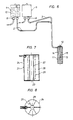
- the container 11 or 21 can be directly on a patient, e.g. to irradiate its blood, which is connected, but it is also possible to connect lines 2 and 3 equipped with shut-off valves 6 to blood bags 4 and 5, in which the liquid 10 to be irradiated is temporarily stored.
- a peristaltic pump 7 attached to the irradiation device 1 the liquid 10 to be irradiated is continuously supplied to the container 11 or 21 during an irradiation process.
- the housing 31 of the radiation device 1 which is surrounded by a casing 39, consists of a lower part 32, in which the receiving chamber 33 of the radiation source 41 is provided, an upper part 34, which has the radiation chamber 35, and an intermediate piece 37 for rotatably mounting the slide 51 in a built-in one Recess 38 composed.
- the upper part 34 is furthermore equipped with a receiving opening 36 for a sealing plug 40 which is enlarged compared to the radiation chamber 35.
- the housing 31 is held by means of supports 50.
- a lifting member 43 is supported on guide rails 47 in the form of a chain drive 45 which can be driven by a motor 44 and to which a plate 46 is attached.
- the radiation source 41 is arranged on a rod 42 which projects from the lower part 32 of the housing 31 and which rests on a plate 46.
- the rod 42 also serves to shield the receiving chamber 33.
- the slide 51 can be adjusted by means of the lever linkage 55 which acts on a shaft 53 attached to the slide 51.
- the lever linkage 55 consists here of an actuating lever 56 rotatably mounted in a bracket 54 by means of a shaft 57, an adjusting lever 58 connected to the shaft 53 of the slide 51 and a connecting lever 59 which is articulated on the actuating lever 56 and the adjusting lever 58.
- the actuating lever 56 is further equipped with a locking member 60 which interacts with a stop 61 which can be adjusted by a bolt 62 against the force of a spring 63.
- a bolt 64 which is connected to the actuating lever 56 is attached and recesses 65, 66 or 67 machined into the console 54, the actuating lever 56 can be locked in the positions A, B or C.
- the sealing plug 40 is held in a height-adjustable manner by means of a bridge 73 on a support frame 71, which has two guide rails 72 for this purpose. And on the bridge 73 a windable chain 75 is attached, which is adjustable by means of a motor 74. In addition, an adjustment cam 76 is attached to the bridge 73, which interacts with the locking member 60 of the actuating lever 56.
- a stepped screw 78 By means of a stepped screw 78, the container 11 or 21 is detachably fastened to the sealing plug 40, on which a cover 77, which extends over the receiving opening 36, is attached. And in order to be able to lead the supply line 2 and the return line 3 out of the radiation chamber 35 when the container 11 or 21 is inserted in the radiation device 1, the sealing plug 40 is provided with a corresponding cutout 68 in the edge region.
- the sealing plug 40 is to be brought into the position shown in FIG. Before that, however, the slide 51 is to be rotated - as shown in FIG. 3 - in such a way that the through bore 52 incorporated into it does not align with the receiving chamber 33, so that the radiation source 41 located therein is also shielded.
- the locking member 60 attached to the operating lever 56 lies in position A of the actuating lever 56 on the stop 61, an unintentional adjustment of the slide 51 is thus excluded.
- the container 11 or 21 is screwed onto the plug 40 and this is inserted into the receiving opening 36.
- the stop 61 is adjusted against the force of the spring 63 acting on the switching cam 76 attached to the bridge 73, the actuating lever 56 can thus be adjusted in position B according to FIG.
- the container 11 or 21 is already in the radiation chamber 35, but the radiation source 41 cannot yet be introduced into it, since the through bore 52 of the slide 51 is not aligned with the receiving chamber 33.
- the radiation device 1 can, for example, be brought into an operating room or the container 11 or 21 can be connected to a patient without radiation being carried out immediately.
- the slide 51 is thereby adjusted via the lever linkage 55, as shown in FIG. 5, in such a way that the radiation source 41 is more or less inserted into the opening 13 or 23 of the container 11 or 21 can be introduced and that the located in or through this flowing medium is irradiated.
- the radiation dose that is supplied to the medium 10 can be regulated.
- a locking cylinder can be installed in the bolt 64 so that the actuating lever 56 is to be secured in positions A, B or C against inadvertent rotation.
- the radiation source 41 or the lifting member 43 assigned to it can be mechanically connected to a display device 81 attached to the casing 39 via connecting members 82. In this way, the position of the radiation source 41 can thus be determined at any time.
- control or display elements 83 or a computer with which an automatic course of treatment can be carried out and / or the radiation values are to be stored can be provided on the casing 39.
Landscapes
- Health & Medical Sciences (AREA)
- Engineering & Computer Science (AREA)
- Heart & Thoracic Surgery (AREA)
- Vascular Medicine (AREA)
- Hematology (AREA)
- General Health & Medical Sciences (AREA)
- High Energy & Nuclear Physics (AREA)
- General Engineering & Computer Science (AREA)
- Anesthesiology (AREA)
- Biomedical Technology (AREA)
- Physics & Mathematics (AREA)
- Life Sciences & Earth Sciences (AREA)
- Animal Behavior & Ethology (AREA)
- Cardiology (AREA)
- Public Health (AREA)
- Veterinary Medicine (AREA)
- Apparatus For Disinfection Or Sterilisation (AREA)
- Infusion, Injection, And Reservoir Apparatuses (AREA)
- External Artificial Organs (AREA)
- Heating, Cooling, Or Curing Plastics Or The Like In General (AREA)
- Radiation-Therapy Devices (AREA)
- Physical Or Chemical Processes And Apparatus (AREA)
Abstract
Description
Die Erfindung bezieht sich auf eine Vorrichtung zum Bestrahlen eines Gegenstandes, insbesondere eines in einem Behälter gelagerten flüssigen oder gasförmigen Mediums, wie beispielsweise Blut, mit einer Strahlungsquelle für ionisierende Strahlen, die in einem abgeschirmten Gehäuse eingesetzt ist und in diesem auf das zu bestrahlende Medium einwirkt.The invention relates to a device for irradiating an object, in particular a liquid or gaseous medium, such as blood, stored in a container, with a radiation source for ionizing radiation, which is inserted in a shielded housing and acts on the medium to be irradiated .
Bei einer bekannten Bestrahlungsvorrichtung dieser Art ist das die Strahlungsquelle aufnehmende Gehäuse in deren Höhe seitlich mit einer offenen Ausnehmung versehen, in dem ein Gehäuseteil verdrehbar gelagert ist, das eine Bestrahlungskammer aufweist. Der zu bestrahlende Gegenstand, z.B. eine Flasche, wird bei dieser Ausgestaltung in die Bestrahlungskammer eingesetzt und kann durch Verdrehen des Gehäuses zur Strahlungsquelle transportiert werden. Da der Gegenstand mittels eines in der Bestrahlungskammer vorgesehenen Drehtellers des weiteren um seine Achse gedreht werden kann, ist zwar eine gleichmäßige Bestrahlung von außen möglich, trotz des erheblichen Bauaufwandes können aber nur in einer Flasche oder in einem Beutel eingefüllte und somit ruhende Medien jeweils von einer Seite der Strahlungsquelle bestrahlt werden. Außerdem ist der Zeitaufwand dazu, da das Behältnis und somit das zu bestrahlende Medium an der Strahlungsquelle vorbeizubewegen ist, erheblich, auch kann sich die Rotationsbewegung des Behältnisses ungünstig auf das zu bestrahlende Medium auswirken. Der Anwendungsbereich dieser Bestrahlungsvorrichtung ist daher begrenzt, da diese insbesondere bei einer Operation, um z.B. während dieser das Blut eines Patienten zu bestrahlen, nicht eingesetzt werden kann.In a known radiation device of this type, the housing receiving the radiation source is laterally provided with an open recess in its height, in which a housing part is rotatably mounted, which has a radiation chamber. In this embodiment, the object to be irradiated, for example a bottle, is inserted into the irradiation chamber and can be turned to the radiation source by rotating the housing be transported. Since the object can also be rotated about its axis by means of a turntable provided in the irradiation chamber, uniform irradiation from the outside is possible, but despite the considerable construction costs, media which are filled in a bottle or in a bag and are therefore stationary can each be from one Side of the radiation source. In addition, the time required for this since the container and thus the medium to be irradiated has to be moved past the radiation source is considerable, and the rotational movement of the container can also have an unfavorable effect on the medium to be irradiated. The field of application of this radiation device is therefore limited, since it cannot be used in particular during an operation, for example in order to irradiate the blood of a patient during it.
Aufgabe der Erfindung ist es demnach, eine Bestrahlungsvorrichtung der vorgenannten Gattung zu schaffen, mittels der nicht nur eine äußerst intensive und gefahrlose Bestrahlung eines Mediums vorzunehmen ist, sondern auch ein fließendes Medium nahe an der Strahlungsquelle vorbeiströmen kann, wobei die auf dieses einwirkende Strahlendosis leicht den Erfordernissen, beispielsweise in Abhängigkeit von der Strömungsgeschwindigkeit, entsprechend einzustellen ist. Ferner soll die Bestückung der Bestrahlungsvorrichtung ohne Schwierigkeiten vorzunehmen und somit soll eine einfache Handhabung gegeben sein, dennoch soll zuverlässig gewährleistet werden, daß keine Strahlen unkontrolliert nach außen gelangen und daß die Bestrahlungsvorrichtung folgerichtig zu bedienen und entsprechend funktionsfähig ist.The object of the invention is therefore to provide an irradiation device of the aforementioned type, by means of which not only an extremely intensive and safe irradiation of a medium is to be carried out, but also a flowing medium can flow close to the radiation source, the radiation dose acting on it easily Requirements, for example depending on the flow rate, must be set accordingly. Furthermore, the equipping of the radiation device should be carried out without difficulty and thus simple handling should be provided, but it should nevertheless be reliably ensured that no rays escape uncontrolledly and that the radiation device can be operated logically and is correspondingly functional.
Gemäß der Erfindung wird dies dadurch erreicht, daß das vorzugsweise in Form einer Tonne ausgebildete Gehäuse auf der einen Seite eine zentrische Aufnahmekammer für die Strahlungsquelle und fluchtend zu dieser auf der anderen Seite eine Bestrahlungskammer zur Aufnahme eines das zu bestrahlende Medium enthaltende Behältnisses aufweist, dass zwischen der Aufnahmekammer und der Bestrahlungskammer ein z.B. verdrehbar oder verschiebbar gelagerter Schieber angeordnet ist, der mit einer Durchgangsöffnung für die in die Bestrahlungskammer einführbare Strahlungsquelle versehen und in unterschiedlichen Winkelstellungen arretierbar ist, und daß die Bestrahlungskammer durch einen zustellbaren Verschlußstopfen verschließbar ist.According to the invention, this is achieved in that the housing, which is preferably designed in the form of a barrel, has a central receiving chamber on one side for the radiation source and in alignment with this on the other side has a radiation chamber for receiving a container containing the medium to be irradiated, that a rotatable or displaceably mounted slide is arranged between the receiving chamber and the radiation chamber, which has a passage opening for the into the radiation chamber insertable radiation source is provided and can be locked in different angular positions, and that the radiation chamber can be closed by an adjustable sealing plug.
Zweckmäßig ist es hierbei, das das zu bestrahlende Medium aufnehmende Behältnis mit einer zentrisch angeordneten Ausnehmung zur Aufnahme der Strahlungsquelle zu versehen, wobei dieses durch einen schraubenlinienförmig um eine die Strahlungsquelle aufnehmenden hohlen Kern gewickelten Schlauch gebildet oder aus zwei mit Abstand ineinander angeordneten Rohren bestehen kann, deren Ringraum durch Zwischenwände in miteinander kommunizierende Strömungskanäle unterteilt ist. Um den Transport des Mediums durch das Behältnis sicherzustellen, sollte dieses an eine Pumpvorrichtung, beispielsweise eine an der Bestrahlungsvorrichtung angebrachte Schlauchpumpe, anschließbar sein.It is expedient here to provide the container to be irradiated with a centrally arranged recess for receiving the radiation source, which can be formed by a helically wound tube around a hollow core receiving the radiation source or can consist of two tubes arranged at a distance from one another, whose annular space is divided by flow walls into communicating flow channels. In order to ensure the transport of the medium through the container, it should be possible to connect it to a pump device, for example a hose pump attached to the radiation device.
Vorteilhaft ist es des weiteren, wenn der Schieber mittels eines Hebelgestänges in drei Betriebsstellungen verstellbar und in diesen arretierbar ist.It is also advantageous if the slide can be adjusted and locked in three operating positions by means of a lever linkage.
Das dazu verwendbare Hebelgestänge kann in einfacher Weise aus einem außerhalb des Gehäuses angeordneten drehbar gelagerten Betätigungshebel, einem an dem Schieber angebrachten Verstellhebel und einem an diesen angelenkten Verbindungshebel bestehen, und dem Betätigungshebel sollte ein in Abhängigkeit von der Betriebsstellung des Verschlußstopfens lösbares Verriegelungsglied zugeordnet sein.The lever linkage that can be used for this purpose can consist in a simple manner of a rotatably mounted actuating lever arranged outside the housing, an adjusting lever attached to the slide and a connecting lever articulated thereon, and the actuating lever a releasable locking member should be assigned depending on the operating position of the sealing plug.
Zweckmäßig ist es ferner, die Strahlungsquelle mittels eines vorzugsweise motorisch antreibbaren Hubgliedes in die Bestrahlungskammer des Gehäuses einzuführen und den Verschlußstopfen mit Hilfe einer Brücke an einem aus zwei Führungsschienen bestehenden Traggestell ebenfalls mittels eines Motors in der Höhe zu verstellen.It is furthermore expedient to introduce the radiation source into the radiation chamber of the housing by means of a preferably motor-driven lifting member and to adjust the height of the sealing plug by means of a bridge on a support frame consisting of two guide rails, likewise by means of a motor.
Angebracht ist es auch, die Brücke mit einem Schaltnocken auszustatten, mittels dem das Verriegelungsglied des dem Schieber zugeordneten Hebelgestänges lösbar ist, und das das zu bestrahlende Medium aufnehmende Behältnis an dem Verschlußstopfen, beispielsweise mittels einer gestuft ausgebildeten Schraube, lösbar zu befestigen.It is also appropriate to equip the bridge with a switching cam, by means of which the locking member of the lever linkage assigned to the slide can be released, and to releasably fasten the container to be irradiated to the sealing plug, for example by means of a stepped screw.
Des weiteren sollte der Verschlußstopfen in eine fluchtend zu der Aufnahmekammer des Behältnisses in das Gehäuse eingearbeitete, erweiterte Aufnahmeöffnung einsetzbar, mit einer die Aufnahmeöffnung übergreifenden Abdeckung und vorzugsweise in seinem Randbereich mit einer Freisparung zur Durchführung von an das Behältnis anzuschließenden Leitungen versehen sein.Furthermore, the sealing plug should be insertable into an enlarged receiving opening that is machined into the housing in alignment with the receiving chamber of the housing, be provided with a cover that overlaps the receiving opening, and preferably in its edge area with a cutout for carrying out lines to be connected to the container.
Das Gehäuse sollte aus fertigungstechnischen Gründen aus einem die Strahlungsquelle aufnehmenden Unterteil, einem Zwischenstück zur verdrehbaren Lagerung des Schiebers und einem das Behältnis aufnehmenden Oberteil zusammengesetzt sein. Ferner kann das Gehäuse mit einer geschlossenen Ummantelung versehen werden, an der auch eine Anzeigeeinrichtung angebracht sein kann, die mechanisch unmittelbar mit der Strahlungsquelle oder deren Hubglied verbunden ist. Wird eine Bestrahlungsvorrichtung gemäß der Erfindung ausgebildet, so ist es ohne Schwierigkeiten möglich, den zu bestrahlenden Gegenstand äußerst intensiv den von der Strahlungsquelle abgegebenen ionisierenden Strahlen auszusetzen, aber dennoch gefahrlos zu bestrahlen; vor allem aber kann auch ein fliessendes Medium problemlos bestrahlt werden. Wird nämlich das Gehäuse der Bestrahlungsvorrichtung mit einer Aufnahmekammer versehen, in die das zu bestrahlende Medium aufnehmende in besonderer Weise gestaltete Behältnis einsetzbar ist und wird die Strahlungsquelle derart angeordnet, daß diese in das Aufnahmebehältnis eingeführt werden kann, wobei mittels eines gesteuert zu betätigenden Schiebers nur in einer vorgegebenen Betriebsstellung die Einführung zu bewerkstelligen ist, so wirken die Strahlen von innen auf das die Strahlungsquelle einschliessende Medium ein. Die Strahlungsintensität wird somit sehr gut ausgenutzt, so daß die Bestrahlungszeit bei Übertragung der gleichen Strahlendosis erheblich kürzer ist als bei der bekannten Vorrichtung.For technical reasons, the housing should be composed of a lower part receiving the radiation source, an intermediate piece for rotatably supporting the slide and an upper part receiving the container. Furthermore, the housing can be provided with a closed casing, to which a display device can also be attached, which is mechanically connected directly to the radiation source or its lifting member. If an irradiation device is designed according to the invention, it is possible without difficulty to expose the object to be irradiated extremely intensively to the ionizing radiation emitted by the radiation source, but to irradiate it safely; but above all, a flowing medium can be irradiated without any problems. If the housing of the irradiation device is provided with a receiving chamber into which the medium to be irradiated can be inserted in a specially designed container, and the radiation source is arranged in such a way that it can be inserted into the receiving container, with a slider to be operated only in If the introduction is to be accomplished in a predetermined operating position, the rays act from the inside on the medium enclosing the radiation source. The radiation intensity is thus used very well, so that the radiation time when transmitting the same radiation dose is considerably shorter than in the known device.
Auch wirken bei der vorschlagsgemäßen Bestrahlungsvorrichtung auf das zu bestrahlende Medium, da das dieses aufnehmende Behältnis während einer Bestrahlung stationär angeordnet ist, keine Zentrifugalkräfte, die u. U. zu Abscheidungen führen können, ein, des weiteren ist die Bestrahlung beispielsweise in Abhängigkeit von der Stellung der Strahlungsquelle, der Bestrahlungsdauer und/oder der Fließgeschwindigkeit des Mediums leicht zu dosieren, gegebenenfalls auch zu programmieren. Insbesondere aber ist von Vorteil, daß ein Medium das Behältnis während einer Bestrahlung durchströmen kann, das Bestrahlungsgerät kann somit auch unmittelbar an einen Patienten angeschlossen oder während einer Operation eingesetzt werden. Aufgrund der einfachen Handhabung und der hohen Betriebssicherheit ist dabei gewährleistet, daß der Einsatz sowohl für das Personal als auch für einen Patienten stets gefahrlos ist. Und da der Behälter und dessen Zuleitung rasch ausgetauscht und steril gehaltenwerden können, ist, zumal auch die Bestrahlungzeit kurz ist, ein hoher Ausnutzungsgrad gegeben. Durch die Anordnung eines nur bei abgeschirmter Bestrahlungskammer zu öffnenden Schiebers zwischen dieser und der Aufnahmekammer der Stahlungsquelle ist ferner gewährleistet, daß eine unkontrollierte Abstrahlung und eine Gefährdung des Personals ausgeschlossen ist.Also, in the radiation device according to the proposal, no centrifugal forces act on the medium to be irradiated, since the receptacle receiving this is arranged in a stationary manner during irradiation. U. lead to deposits, a, furthermore, the radiation can be easily dosed, for example depending on the position of the radiation source, the duration of the radiation and / or the flow rate of the medium, possibly also programmed. In particular, however, it is advantageous that a medium can flow through the container during irradiation Radiation equipment can thus also be connected directly to a patient or used during an operation. The simple handling and the high level of operational safety ensure that the use is always safe for both the staff and a patient. And since the container and its supply line can be quickly replaced and kept sterile, there is a high degree of utilization, especially since the irradiation time is short. The arrangement of a slide which can only be opened when the radiation chamber is shielded, between the latter and the receiving chamber of the radiation source also ensures that uncontrolled radiation and a risk to personnel are excluded.
In der Zeichnung ist ein Ausführungsbeispiel der gemäß der Erfindung ausgebildeten Bestrahlungsvorrichtung dargestellt, das nachfolgend im einzelnen erläutert ist. Hierbei zeigt:
- Figur 1
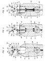
- die Bestrahlungsvorrichtung während eines Bestückungsvorganges in einem Axialschnitt,
Figur 2- die Vorrichtung nach Figur 1 in Seitenansicht während einer Bestrahlung,
Figuren 3 bis 5- die unterschiedlichen Betriebsstellungen des mittels eines Hebelgestänge betätigbaren Schiebers, der Bestrahlungsvorrichtung nach den Figuren 1 und 2,
Figur 6- das bei der Bestrahlungsvorrichtung nach den Figuren 1 und 2 vorgesehene Behältnis zur Aufnahme eines zu bestrahlenden flüssigen Mediums,
Figur 7- eine andersartige Ausgestaltung eines derartigen Behältnisses in einem Axialschnitt und
- Figur 8
- das Behältnis nach
Figur 7 in Draufsicht.
- Figure 1
- the radiation device during an assembly process in an axial section,
- Figure 2
- 2 shows the device according to FIG. 1 in a side view during irradiation,
- Figures 3 to 5
- the different operating positions of the slide which can be actuated by means of a lever linkage, the irradiation device according to FIGS. 1 and 2,
- Figure 6
- the container provided in the irradiation device according to FIGS. 1 and 2 for receiving a liquid medium to be irradiated,
- Figure 7
- a different design of such a container in an axial section and
- Figure 8
- the container of Figure 7 in plan view.
Die in den Figuren 1 und 2 dargestellte und mit 1 bezeichnete Vorrichtung dient zum Bestrahlen eines Gegenstandes, vorzugsweise eines flüssigen Mediums 10 mit ionisierenden Strahlen, das über eine Zuführungsleitung 2 einem Behältnis 11 zuströmen kann, das in die Vorrichtung 1 einsetzbar ist. Dazu sind in einem tonnenförmig ausgebildeten Gehäuse 31 eine Aufnahmekammer 33 für eine Strahlungsquelle 41 sowie eine Bestrahlungskammer 35 eingearbeitet, in die die Strahlungsquelle 41 einführbar ist. Zwischen der Aufnahmekammer 33 und der Bestrahlungskammer 35 ist des weiteren ein mittels eines Hebelgestänges 55 gesteuert verstellbarer Schieber 51 angeordnet, durch den die Aufnahmekammer 33 der Strahlungsquelle 41 bei einer Beschickung der Vorrichtung 1, wie dies in Figur 1 dargestellt ist, abgeschirmt ist.The device shown in FIGS. 1 and 2 and designated 1 serves to irradiate an object, preferably a
Der Behälter 11 zur Aufnahme der zu bestrahlenden Flüssigkeit 10 besteht, wie dies im einzelnen der Figur 6 zu entnehmen ist, aus einem auf einem hohlen Kern 12 schraubenlinienförmig aufgewickelten Schlauch 14 und einer Ummantelung 15, so daß eine Öffnung 13 gebildet ist, in die die Strahlungsquelle 41 eingeführt werden kann. Gemäß den Figuren 7 und 8 kann der dort dargestellte Behälter 21 aber auch aus einem Innenrohr 22 und einem mit Abstand zu diesem angeordneten Außenrohr 24 hergestellt werden, zwischen denen Zwischenwände 25 derart eingesetzt sind, daß miteinander kommunizierende Strömungskanäle 26 geschaffen sind. Die Strahlungsquelle 41 kann bei dieser Ausgestaltung während eines Bestrahlungsvorganges in die Öffnung 23 des Innenrohres 22 eingeführt werden.The
Über die Zuführungsleitung 2 sowie eine Rückführungsleitung 3 kann das Behältnis 11 bzw. 21 unmittelbar an einem Patienten, um z.B. dessen Blut zu bestrahlen, angeschlossen weraen, es ist aber auch möglich, an die mit Absperrventilen 6 ausgestatteten Leitungen 2 und 3 Blutbeutel 4 und 5 anzuschließen, in denen die zu bestrahlende Flüssigkeit 10 zwischengelagert wird. Mittels einer an der Bestrahlungsvorrichtung 1 angebrachten Schlauchpumpe 7 wird die zu bestrahlende Flüssigkeit 10 dem Behältnis 11 bzw. 21 während eines Bestrahlungsvorganges kontinuierlich zugeführt.Via the
Das von einer Ummantelung 39 umgebene Gehäuse 31 der Bestrahlungsvorrichtung 1 ist aus einem Unterteil 32, in dem die Aufnahmekammer 33 der Strahlungsquelle 41 vorgesehen ist, einem die Bestrahlungskammer 35 aufweisenden Oberteil 34 und einem Zwischenstück 37 zur verdrehbaren Lagerung des Schiebers 51 in einer in dieses eingearbeiteten Ausnehmung 38 zusammengesetzt. Das Oberteil 34 ist des weiteren mit einer gegenüber der Bestrahlungskammer 35 erweiterten Aufnahmeöffnung 36 für einen Verschlußstopfen 40 ausgestattet. Mittels Stützen 50 ist das Gehäuse 31 gehalten.The
Zur Verstellung der in die Bestrahlungskammer 35 einführbaren und somit höhenverstellbar angeordneten Strahlungsquelle 41 dient ein auf Führungsschienen 47 abgestütztes Hubglied 43 in Form eines durch einen Motor 44 antreibbaren Kettentriebes 45, an dem eine Platte 46 angebracht ist. Und die Strahlungsquelle 41 ist auf einer aus dem Unterteil 32 des Gehäuses 31 ragenden Stange 42 angeordnet, die auf einer Platte 46 ruht. Die Stange 42 dient auch zur Abschirmung der Aufnahmekammer 33. Durch eine Verdrehung des Kettentriebes 45 im Uhrzeigersinn kann somit die Strahlungsquelle 41 angehoben und bei entsprechender Stellung des Schiebers 51 ganz oder teilweise, je nach Dosierung in die Bestrahlungskammer 35 eingeführt werden. Die Verstellbewegungen des Hubgliedes 43 werden mittels Endschalter 48 und 49 überwacht.To adjust the
Damit die Strahlungsquelle 41 in einer bestimmten Stellung des Schiebers 51 in die Bestrahlungskammer 35 eingeschoben werden kann, ist dieser mit einer Durchgangsbohrung 52 versehen. Die Verstellung des Schiebers 51 ist mittels des Hebelgestänges 55 zu bewerkstelligen, das auf eine an einer an dem Schieber 51 angebrachten Welle 53 einwirkt.So that the
Das Hebelgestänge 55 besteht hierbei aus einem mittels einer Welle 57 drehbar in einer Konsole 54 gelagerten Betätigungshebel 56, einem mit der Welle 53 des Schiebers 51 verbundenen Verstellhebel 58 sowie einem Verbindungshebel 59, der an dem Betätigungshebel 56 sowie dem Verstellhebel 58 angelenkt ist. Der Betätigungshebel 56 ist des weiteren mit einem Riegelglied 60 ausgestattet, das mit einem um einen Bolzen 62 entgegen der Kraft einer Feder 63 verstellbaren Anschlag 61 zusammenwirkt. Mittels eines Riegels 64, der an dem Betätigungshebel 56 angebracht und in die Konsole 54 eingearbeitete Ausnehmungen 65, 66 oder 67 einführbar ist, ist der Betätigungshebel 56 in den Stellungen A, B oder C arretierbar.The
Der Verschlußstopfen 40 ist mittels einer Brücke 73 höhenverstellbar an einem Traggestell 71 gehalten, das dazu zwei Führungsschienen 72 aufweist. Und an der Brücke 73 ist eine aufwickelbare Kette 75 befestigt, die mit Hilfe eines Motors 74 verstellbar ist. Außerdem ist an der Brücke 73 ein Verstellnocken 76 angebracht, der mit dem Riegelglied 60 des Betätigungshebels 56 zusammenwirkt. Mittels einer abgestuft ausgebildeten Schraube 78 ist das Behältnis 11 bzw. 21 abnehmbar an dem Verschlußstopfen 40, an dem eine die Aufnahmeöffnung 36 übergreifende Abdeckung 77 angebracht ist, befestigt. Und um die Zuführungsleitung 2 sowie die Rückführungsleitung 3 bei in die Bestrahlungsvorrichtung 1 eingesetztem Behältnis 11 bzw. 21 aus der Bestrahlungskammer 35 herausführen zu können, ist der Verschlußstopfen 40 im Randbereich mit einer entsprechenden Freisparung 68 versehen.The sealing
Soll ein Behältnis 11 bzw. 21 in die Bestrahlungsvorrichtung 1 eingesetzt werden, so ist der Verschlußstopfen 40 in die in Figur 1 gezeigte Stellung zu bringen. Vorher ist der Schieber 51 jedoch derart zu verdrehen - wie dies in Figur 3 dargestellt ist -, daß die in diesen eingearbeitete Durchgangsbohrung 52 nicht mit der Aufnahmekammer 33 fluchtet, damit die in dieser befindliche Strahlungsquelle 41 auch abgeschirmt ist. Das an dem Betätigungshebel 56 angebrachte Riegelglied 60 liegt in Position A des Betätigungshebels 56 an dem Anschlag 61 an, eine unabsichtliche Verstellung des Schiebers 51 ist somit ausgeschlossen.If a
Sodann wird das Behältnis 11 bzw. 21 an dem Verschlußstopfen 40 festgeschraubt und dieser wird in die Aufnahmeöffnung 36 eingesetzt. Dabei wird mittels des an der Brücke 73 angebrachten Schaltnockens 76 der Anschlag 61 entgegen der Kraft der auf diesen einwirkenden Feder 63 verstellt, der Betätigungshebel 56 kann somit in Position B gemäß Figur 4 verstellt werden. In diesem Betriebszustand befindet sich das Behältnis 11 bzw. 21 bereits in der Bestrahlungskammer 35, die Strahlungsquelle 41 kann aber noch nicht in diese eingeführt werden, da die Druchgangsbohrung 52 des Schiebers 51 nicht mit der Aufnahmekammer 33 fluchtet.Then the
In dieser Betriebsstellung kann die Bestrahlungsvorrichtung 1 beispielsweise in einen Operationssaal gebracht oder das Behältnis 11 bzw. 21 kann an einen Patienten angeschlossen werden, ohne daß sofort eine Bestrahlung vorgenommen wird.In this operating position, the radiation device 1 can, for example, be brought into an operating room or the
Wird allerdings der Betätigungshebel 56 in Position C weitergedreht, so wird dadurch der Schieber 51 über das Hebelgestänge 55, wie dies in Figur 5 gezeigt ist, derart verstellt, daß die Strahlungsquelle 41 mit Hilfe des Hubgliedes 43 mehr oder weniger in die Öffnung 13 bzw. 23 des Behältnisses 11 bzw. 21 eingeführt werden kann und daß das in diesem befindliche oder durch diese strömende Medium bestrahlt wird. In Abhängigkeit von der Durchflußgeschwindigkeit des Mediums, der Stellung der Strahlungsquelle 41 und/oder der Zeitdauer der Bestrahlung kann hierbei die Strahlendosis, die dem Medium 10 zugeführt wird, geregelt werden.However, if the actuating
In dem Riegel 64 kann ein Schließzylinder eingebaut sein, damit der Betätigungshebel 56 in den Positionen A, B oder C gegen unbeabsichtigtes Verdrehen zu sichern ist. Auch kann, wie dies in Figur 1 strichpunktiert eingezeichnet ist, die Strahlungsquelle 41 oder das dieser zugeordnete Hubglied 43 über Verbindungsglieder 82 mechanisch mit einer an der Ummantelung 39 angebrachten Anzeigeeinrichtung 81 verbunden sein. Auf diese Weise kann somit die Lage der Strahlungsquelle 41 jederzeit bestimmt werden. Des weiteren können an der Ummantelung 39 Kontroll- oder Anzeigeelemente 83 oder ein Rechner, mit dem ein automatischer Ablauf einer Behandlung zu bewerkstelligen ist und/oder die Bestrahlungswerte zu speichern sind, vorgesehen sein.A locking cylinder can be installed in the
Claims (18)
- A device for irradiating an object, in particular a liquid or gaseous medium such as blood which is stored inside a container, with a radiation source for ionizing beams placed within a shielded housing in which it influences the medium to be irradiated,
characterized in that,
the housing (31) is preferably formed in the shape of a barrel with a central accommodation chamber (33) for the radiation source (41) at one end and, flush with the accommodation chamber (33), an irradiation chamber (35) on the other end for holding a container (11; 21) containing the medium (10) to be irradiated, that a slide valve (51) which is mounted so it can be turned or pushed, for example, is arranged between the accommodation chamber (33) and the irradiation chamber (35) with the aforementioned slide valve (51) having a passageway (52) for the radiation source (41) which can be inserted into the irradiation chamber (35) and being lockable in various angled settings, and that the irradiation chamber (35) can be closed by a plug (40) which can be moved towards it. - The irradiation device in accordance with Claim 1,
characterized in that,
the container (11; 21) holding the medium (liquid 10) to be irradiated has a central recess (13; 23) for accommodating the radiation source (41). - The irradiation device in accordance with Claim 2,
characterized in that,
the container (11) is formed by a helically shaped hose (14) wrapped around a hollow core (13) which accommodates the radiation source (41). - The irradiation device in accordance with Claim 2,
characterized in that,
the container (21) is formed by two tubes (22, 24) arranged one inside the other with a gap in between, and that the annular space enclosed by the tubes (22, 24) is sub-divided by intermediate walls (25) into intercommunicating flow channels (26). - The irradiation device in accordance with one or more of Claims 2 to 4,
characterized in that,
the container (11; 21) can be connected to a pump device (7), for example a hose pump attached to the irradiation device (1). - The irradiation device in accordance with one or more of Claims 1 to 5,
characterized in that,
the slide valve (51) can be set to three operating positions (A, B, C) in which it can be locked. - The irradiation device in accordance with Claim 6,
characterized in that,
the lever linkage (55) is formed from an actuation lever (56) mounted so as to rotate and located outside the housing (31), from an adjustment lever (58) attached to the slide valve (51) and from a connection lever (59) hinged on the adjustment lever (58). - The irradiation device in accordance with Claim 7,
characterized in that,
the actuation lever (56) is assigned to a locking element (60) which can be released depending on the operating position of the plug (40). - The irradiation device in accordance with one or more of Claims 1 to 8,
characterized in that,
the radiation source (41) can be inserted into the irradiation chamber (35) of the housing (31) by means of a stroke element (43) which can preferably be driven by a motor. - The irradiation device in accordance with one or more of Claims 1 to 9,
characterized in that,
the plug (40) is guided on a carrier frame (71) by means of a bridge (73) with the carrier frame (71) consisting of two guide rails (72), and the height of the plug (40) can be adjusted using a motor (74). - The irradiation device in accordance with one or more of Claims 1 to 10,
characterized in that,
the bridge (73) has a switching cam (76) by means of which the locking element (60) of the lever linkage (55) assigned to the slide valve (51) can be released. - The irradiation device in accordance with one or more of Claims 1 to 11,
characterized in that,
the container (11; 21) holding the medium (liquid 10) to be irradiated is fixed onto the plug (40) in a releasable connection, for example by means of a stepped screw (78). - The irradiation device in accordance with one or more of Claims 1 to 12,
characterized in that,
the plug (40) can be inserted in an expanded accommodation opening (36) worked into the housing (31) and flush with the accommodation chamber (35) of the container (11; 21). - The irradiation device in accordance with Claim 13,
characterized in that,
the plug (40) has a cover (77) extending beyond the accommodation opening (36). - The irradiation device in accordance with one or more of Claims 1 to 14,
characterized in that,
the plug (40) preferably has a notch (68) in its edge for passing through cables (2, 3) for connection to the container (11; 21). - The irradiation device in accordance with one or more of Claims 1 to 15,
characterized in that,
the housing (31) is composed of a base part (32) which accommodates the radiation source (41), of an adapter (37) for mounting the slide valve (51) so it can rotate and of an upper part (34) which accommodates the container (11; 21). - The irradiation device in accordance with one or more of Claims 1 to 16,
characterized in that,
the housing (31) has a closed jacket (39). - The irradiation device in accordance with one or more of Claims 1 to 17,
characterized in that,
a display device (31) is attached to the jacket (39) of the housing (31) and this display device (31) has a direct mechanical connection to the radiation source (41) or its stroke element (43).
Applications Claiming Priority (2)
| Application Number | Priority Date | Filing Date | Title |
|---|---|---|---|
| DE4012398 | 1990-04-19 | ||
| DE4012398A DE4012398A1 (en) | 1990-04-19 | 1990-04-19 | RADIATION DEVICE |
Publications (3)
| Publication Number | Publication Date |
|---|---|
| EP0452637A2 EP0452637A2 (en) | 1991-10-23 |
| EP0452637A3 EP0452637A3 (en) | 1992-11-25 |
| EP0452637B1 true EP0452637B1 (en) | 1996-09-25 |
Family
ID=6404606
Family Applications (1)
| Application Number | Title | Priority Date | Filing Date |
|---|---|---|---|
| EP91102780A Expired - Lifetime EP0452637B1 (en) | 1990-04-19 | 1991-02-26 | Irradiation device |
Country Status (6)
| Country | Link |
|---|---|
| US (1) | US5134295A (en) |
| EP (1) | EP0452637B1 (en) |
| JP (1) | JPH04225200A (en) |
| AT (1) | ATE143524T1 (en) |
| CA (1) | CA2040546A1 (en) |
| DE (2) | DE4012398A1 (en) |
Families Citing this family (25)
| Publication number | Priority date | Publication date | Assignee | Title |
|---|---|---|---|---|
| DE4116022C2 (en) * | 1991-05-16 | 1995-03-23 | Isotopentechnik Dr Sauerwein G | Shielding body of a gammagraphy device |
| NL9300827A (en) * | 1993-05-13 | 1994-12-01 | Valery Kotul | Means for the treatment of human blood |
| US20040067157A1 (en) * | 1993-07-22 | 2004-04-08 | Clearant, Inc. | Methods for sterilizing biological materials |
| US5362442A (en) * | 1993-07-22 | 1994-11-08 | 2920913 Canada Inc. | Method for sterilizing products with gamma radiation |
| AU732122B2 (en) * | 1996-11-06 | 2001-04-12 | Stephen John Newlands | Isotope holder |
| US6342265B1 (en) * | 1997-08-20 | 2002-01-29 | Triumf | Apparatus and method for in-situ thickness and stoichiometry measurement of thin films |
| US7070607B2 (en) * | 1998-01-27 | 2006-07-04 | The Regents Of The University Of California | Bioabsorbable polymeric implants and a method of using the same to create occlusions |
| US6452200B1 (en) | 1999-05-13 | 2002-09-17 | Mds Nordion Inc. | Gap shielded container for a radioactive source |
| US20040086420A1 (en) * | 2000-03-23 | 2004-05-06 | Macphee Martin J. | Methods for sterilizing serum or plasma |
| US6682695B2 (en) * | 2001-03-23 | 2004-01-27 | Clearant, Inc. | Methods for sterilizing biological materials by multiple rates |
| US6696060B2 (en) * | 2001-06-14 | 2004-02-24 | Clearant, Inc. | Methods for sterilizing preparations of monoclonal immunoglobulins |
| US20030031584A1 (en) * | 2001-08-10 | 2003-02-13 | Wilson Burgess | Methods for sterilizing biological materials using dipeptide stabilizers |
| US6946098B2 (en) | 2001-08-10 | 2005-09-20 | Clearant, Inc. | Methods for sterilizing biological materials |
| US7252799B2 (en) * | 2001-08-31 | 2007-08-07 | Clearant, Inc. | Methods for sterilizing preparations containing albumin |
| US6749851B2 (en) | 2001-08-31 | 2004-06-15 | Clearant, Inc. | Methods for sterilizing preparations of digestive enzymes |
| US20110091353A1 (en) * | 2001-09-24 | 2011-04-21 | Wilson Burgess | Methods for Sterilizing Tissue |
| US20030095890A1 (en) * | 2001-09-24 | 2003-05-22 | Shirley Miekka | Methods for sterilizing biological materials containing non-aqueous solvents |
| US6783968B2 (en) | 2001-09-24 | 2004-08-31 | Clearant, Inc. | Methods for sterilizing preparations of glycosidases |
| US20030185702A1 (en) * | 2002-02-01 | 2003-10-02 | Wilson Burgess | Methods for sterilizing tissue |
| US20030124023A1 (en) * | 2001-12-21 | 2003-07-03 | Wilson Burgess | Method of sterilizing heart valves |
| US6908591B2 (en) * | 2002-07-18 | 2005-06-21 | Clearant, Inc. | Methods for sterilizing biological materials by irradiation over a temperature gradient |
| US20040013562A1 (en) * | 2002-07-18 | 2004-01-22 | Wilson Burgess | Methods for sterilizing milk. |
| AU2003270451A1 (en) * | 2003-01-21 | 2004-08-23 | Safe Foods Corporation | Modular, high volume, high pressure liquid disinfection using uv radiation |
| DE102010054569A1 (en) * | 2010-12-15 | 2012-06-21 | Volodymyr Granovskyy | Container for storing radio-active material, has inner container comprising opening that is closed by stopper, platform provided for fastening pattern to be irradiated and arranged on stopper, and channel formed in stopper |
| CN104662644B (en) | 2012-09-27 | 2018-11-27 | 斯克林集团公司 | Handle liquid supplying device and method, treatment fluid and substrate board treatment and method |
Family Cites Families (10)
| Publication number | Priority date | Publication date | Assignee | Title |
|---|---|---|---|---|
| GB792683A (en) * | 1955-10-21 | 1958-04-02 | Nuclear Engineering Ltd | An improved apparatus for utilising the emanations from radio-active sources for medical therapy and other purposes |
| US2968734A (en) * | 1956-01-06 | 1961-01-17 | Martin Co | Device for the exposure of fluid to radiation |
| IL24713A (en) * | 1964-12-02 | 1969-06-25 | Saint Gobain Techn Nouvelles | Method and apparatus for irradiation of articles |
| FR2020234A1 (en) * | 1968-10-09 | 1970-07-10 | Atomenergi Ab | |
| US3683183A (en) * | 1969-06-04 | 1972-08-08 | Radiation Machinery Corp | A flow-through irradiator for the extra corporeal irradiation of fluid |
| AT341049B (en) * | 1975-10-01 | 1978-01-10 | Oesterr Studien Atomenergie | REACTOR FOR THE CONTINUOUS REVOLUTION OF MEDIUM FLOWING IN A PIPE UNDER THE EFFECT OF IONIZING RADIATION |
| FR2443122A1 (en) * | 1978-11-14 | 1980-06-27 | Commissariat Energie Atomique | DEVICE FOR STORING A PHOTON SOURCE AND FOR IRRADIATION OF A BODY BY RADIATION OF THE SOURCE |
| US4464330A (en) * | 1982-05-13 | 1984-08-07 | The United States Of America As Represented By The Department Of Energy | Apparatus for irradiating a continuously flowing stream of fluid |
| SE8301762L (en) * | 1983-03-30 | 1984-10-01 | Larsson L P Ab | DEVICE FOR MAGNIFICATION OF MICRO-ORGANISMS |
| DE3707586A1 (en) * | 1986-03-13 | 1987-11-12 | Zahnradfabrik Friedrichshafen | DEVICE FOR RADIATING LIQUIDS WITH RADIOACTIVE RAYS |
-
1990
- 1990-04-19 DE DE4012398A patent/DE4012398A1/en not_active Withdrawn
-
1991
- 1991-02-26 EP EP91102780A patent/EP0452637B1/en not_active Expired - Lifetime
- 1991-02-26 DE DE59108216T patent/DE59108216D1/en not_active Expired - Fee Related
- 1991-02-26 AT AT91102780T patent/ATE143524T1/en not_active IP Right Cessation
- 1991-03-29 US US07/677,586 patent/US5134295A/en not_active Expired - Fee Related
- 1991-04-16 JP JP3084174A patent/JPH04225200A/en active Pending
- 1991-04-16 CA CA002040546A patent/CA2040546A1/en not_active Abandoned
Also Published As
| Publication number | Publication date |
|---|---|
| JPH04225200A (en) | 1992-08-14 |
| US5134295A (en) | 1992-07-28 |
| CA2040546A1 (en) | 1991-10-20 |
| ATE143524T1 (en) | 1996-10-15 |
| EP0452637A3 (en) | 1992-11-25 |
| DE4012398A1 (en) | 1991-10-24 |
| DE59108216D1 (en) | 1996-10-31 |
| EP0452637A2 (en) | 1991-10-23 |
Similar Documents
| Publication | Publication Date | Title |
|---|---|---|
| EP0452637B1 (en) | Irradiation device | |
| EP0128300B1 (en) | Pipe canal distributing points, especially for the medical radiation technique | |
| WO2001000276A1 (en) | Device for carrying out proton therapy | |
| DE3342470C2 (en) | ||
| EP0766978A1 (en) | Means to seal fix and to disengage a receptacle against a cover | |
| CH636056A5 (en) | Abfuellvorrichtung for liquids. | |
| CH650355A5 (en) | RADIOISOTOPE GENERATOR. | |
| DE10065283A1 (en) | Centrifuge with blood bag system with upper and lower outlet | |
| DE2942384C2 (en) | ||
| DE3620123A1 (en) | MEASURING AND RADIATION DEVICE FOR CAVITIES | |
| DE3221350A1 (en) | DEVICE FOR PROVIDING HIGH PURITY, STERILE WATER | |
| EP0115276A2 (en) | Fluid flow control device | |
| CH645420A5 (en) | Outside held cylindrical wide bracket for hose ware. | |
| DE60204114T2 (en) | Recharger, cassette and device for changing a reload cassette | |
| EP0230010B1 (en) | Dental tool | |
| DE2610290A1 (en) | Filterless sterilisation vessel for prevacuum operation - has a double acting valve, acts quickly and is easily checked for correct functioning | |
| DE2951375C2 (en) | ||
| DE60004332T2 (en) | CONTAINER FOR RADIOACTIVE SUBSTANCES | |
| DE3915289A1 (en) | Treatment of disorders of alimentary canal - by injection of therapeutic medium into zone sealed by inflatable balloons | |
| WO1997014270A1 (en) | Microwave oven, especially for a laboratory | |
| DE357578C (en) | Device for treating liquids with ultraviolet rays | |
| DE3514304C2 (en) | ||
| WO2006027253A1 (en) | Device for brachytherapy with at least one radiation source for introduction into the body | |
| DE3218407C2 (en) | Implantable dosing device | |
| DE826691C (en) | Guide mechanism for cassette holder in cameras |
Legal Events
| Date | Code | Title | Description |
|---|---|---|---|
| PUAI | Public reference made under article 153(3) epc to a published international application that has entered the european phase |
Free format text: ORIGINAL CODE: 0009012 |
|
| AK | Designated contracting states |
Kind code of ref document: A2 Designated state(s): AT BE CH DE ES FR GB IT LI NL SE |
|
| PUAL | Search report despatched |
Free format text: ORIGINAL CODE: 0009013 |
|
| AK | Designated contracting states |
Kind code of ref document: A3 Designated state(s): AT BE CH DE ES FR GB IT LI NL SE |
|
| 17P | Request for examination filed |
Effective date: 19930518 |
|
| 17Q | First examination report despatched |
Effective date: 19950201 |
|
| GRAA | (expected) grant |
Free format text: ORIGINAL CODE: 0009210 |
|
| AK | Designated contracting states |
Kind code of ref document: B1 Designated state(s): AT BE CH DE ES FR GB IT LI NL SE |
|
| PG25 | Lapsed in a contracting state [announced via postgrant information from national office to epo] |
Ref country code: IT Free format text: LAPSE BECAUSE OF FAILURE TO SUBMIT A TRANSLATION OF THE DESCRIPTION OR TO PAY THE FEE WITHIN THE PRE;WARNING: LAPSES OF ITALIAN PATENTS WITH EFFECTIVE DATE BEFORE 2007 MAY HAVE OCCURRED AT ANY TIME BEFORE 2007. THE CORRECT EFFECTIVE DATE MAY BE DIFFERENT FROM THE ONE RECORDED.SCRIBED TIME-LIMIT Effective date: 19960925 Ref country code: FR Effective date: 19960925 Ref country code: GB Effective date: 19960925 Ref country code: ES Free format text: THE PATENT HAS BEEN ANNULLED BY A DECISION OF A NATIONAL AUTHORITY Effective date: 19960925 Ref country code: NL Free format text: LAPSE BECAUSE OF FAILURE TO SUBMIT A TRANSLATION OF THE DESCRIPTION OR TO PAY THE FEE WITHIN THE PRESCRIBED TIME-LIMIT Effective date: 19960925 |
|
| REF | Corresponds to: |
Ref document number: 143524 Country of ref document: AT Date of ref document: 19961015 Kind code of ref document: T |
|
| REF | Corresponds to: |
Ref document number: 59108216 Country of ref document: DE Date of ref document: 19961031 |
|
| PG25 | Lapsed in a contracting state [announced via postgrant information from national office to epo] |
Ref country code: SE Effective date: 19961225 |
|
| EN | Fr: translation not filed | ||
| PG25 | Lapsed in a contracting state [announced via postgrant information from national office to epo] |
Ref country code: AT Free format text: LAPSE BECAUSE OF NON-PAYMENT OF DUE FEES Effective date: 19970226 |
|
| PG25 | Lapsed in a contracting state [announced via postgrant information from national office to epo] |
Ref country code: LI Effective date: 19970228 Ref country code: CH Effective date: 19970228 Ref country code: BE Effective date: 19970228 |
|
| NLV1 | Nl: lapsed or annulled due to failure to fulfill the requirements of art. 29p and 29m of the patents act | ||
| GBV | Gb: ep patent (uk) treated as always having been void in accordance with gb section 77(7)/1977 [no translation filed] |
Effective date: 19960925 |
|
| PLBE | No opposition filed within time limit |
Free format text: ORIGINAL CODE: 0009261 |
|
| STAA | Information on the status of an ep patent application or granted ep patent |
Free format text: STATUS: NO OPPOSITION FILED WITHIN TIME LIMIT |
|
| 26N | No opposition filed | ||
| REG | Reference to a national code |
Ref country code: CH Ref legal event code: PL |
|
| PGFP | Annual fee paid to national office [announced via postgrant information from national office to epo] |
Ref country code: DE Payment date: 20010414 Year of fee payment: 11 |
|
| PG25 | Lapsed in a contracting state [announced via postgrant information from national office to epo] |
Ref country code: DE Free format text: LAPSE BECAUSE OF NON-PAYMENT OF DUE FEES Effective date: 20020903 |