EP0452578A1 - Pulse wave detecting apparatus - Google Patents
Pulse wave detecting apparatus Download PDFInfo
- Publication number
- EP0452578A1 EP0452578A1 EP90304161A EP90304161A EP0452578A1 EP 0452578 A1 EP0452578 A1 EP 0452578A1 EP 90304161 A EP90304161 A EP 90304161A EP 90304161 A EP90304161 A EP 90304161A EP 0452578 A1 EP0452578 A1 EP 0452578A1
- Authority
- EP
- European Patent Office
- Prior art keywords
- pulse wave
- optimum
- pressure sensing
- force
- pulse
- Prior art date
- Legal status (The legal status is an assumption and is not a legal conclusion. Google has not performed a legal analysis and makes no representation as to the accuracy of the status listed.)
- Granted
Links
Images

Classifications
-
- A—HUMAN NECESSITIES
- A61—MEDICAL OR VETERINARY SCIENCE; HYGIENE
- A61B—DIAGNOSIS; SURGERY; IDENTIFICATION
- A61B5/00—Measuring for diagnostic purposes; Identification of persons
- A61B5/02—Detecting, measuring or recording pulse, heart rate, blood pressure or blood flow; Combined pulse/heart-rate/blood pressure determination; Evaluating a cardiovascular condition not otherwise provided for, e.g. using combinations of techniques provided for in this group with electrocardiography or electroauscultation; Heart catheters for measuring blood pressure
- A61B5/021—Measuring pressure in heart or blood vessels
- A61B5/022—Measuring pressure in heart or blood vessels by applying pressure to close blood vessels, e.g. against the skin; Ophthalmodynamometers
Abstract
Description
- The present invention relates to an apparatus for detecting a pulse wave produced from an arterial vessel of a subject.
- There is known a pulse wave detecting apparatus including (1) a pulse wave sensor having a press surface on which one or more pressure sensing elements are provided, the pulse wave sensor being pressed against an arterial vessel of a subject via a body surface above the arterial vessel so that the one or more pressure sensing elements detect a pulse wave produced from the arterial vessel of the subject, (2) pressing means for pressing the pulse wave sensor against the arterial vessel via the body surface, while varying the pressing force over a predetermined force range, and (3) means for determining an optimum, pulse wave sensor pressing force based on the pulse wave (pulses of the pulse wave) which is detected by the one or more pressure sensing elements while the pressing force is varied, and (4) means for obtaining a pulse wave of the subject through the pulse wave sensor pressed with the thus determined optimum pressing force. The conventional apparatus determines as the optimum pulse wave sensor pressing force a pressing force at which the pulse wave sensor (one or more pressure sensing elements) detects a pulse of the pulse wave whose amplitude is maximum, namely, the greatest of the amplitudes of the pulses detected by the pulse wave sensor in the process of varying the pressing force.
- However, generally the thus determined optimum pressing force does not fall to around the middle value of a pressing force range which covers pressing force values at which a pulse wave having a sufficiently great amplitude is detected. Accordingly, in the event that the pulse wave sensor pressing force is changed from the optimum pressing force to a greater or smaller value due to physical motion of the subject or other causes, the conventional apparatus may fail to detect a pulse wave having a sufficiently great amplitude.
- It is therefore an abject of the present invention to provide a pulse wave detecting apparatus capable of detecting a pulse wave having a sufficiently great amplitude irrespective of change in the pulse wave sensor pressing force.
- The above object has been achieved by the present invention, which provides a pulse wave detecting apparatus for detecting a pulse wave produced from an arterial vessel of a subject, comprising (a) a pulse wave sensor having a press surface on which at least one pressure sensing element is provided, the pulse wave sensor being pressed against an arterial vessel of a subject via a body surface above the arterial vessel so that the at least one pressure sensing element detects a pulse wave produced from the arterial vessel of the subject, (b) pressing means for pressing the pulse wave sensor against the arterial vessel via the body surface, while varying the pressing force over a predetermined force range, (c) first means for determining an amplitude of each of pulses of the pulse wave which are detected by the at least one pressure sensing element while the pressing force of the pressing means is varied, (d) second means for determining, based on the pulse amplitudes determined by the first means, a first force range of the pressing force within which the pulse amplitudes are generally constant, the first force range including a point at which a rate of change of the pulse amplitudes with respect to the pressing force is zero, (e) third means for determining a minimum value of the each pulse of the pulse wave detected by the at least one pressure sensing element, (f) fourth means for determining, based on the pulse minimum values determined by the third means, a second force range of the pressing force within which the pulse minimum values are generally constant, the second force range including a point at which a rate of change of the pulse minimum values with respect to the pressing force is minimum, (g) fifth means for determining an optimum force range of the pressing force based on the first and second force ranges, and determining an optimum value of the pressing force such that the optimum value falls within the optimum force range, and (h) sixth means for adjusting the pressing means to the optimum value of the pressing force, and obtaining a pulse wave of the subject through the pulse wave sensor pressed against the arterial vessel with the optimum pressing force.
- In the pulse wave detecting apparatus constructed as described above, the optimum force range of the pulse wave sensor pressing force is determined based on the first force range within which the pulse amplitudes are generally constant and which covers a pressing force at which the pulse wave sensor has detected a pulse having a maximum amplitude, and the second force range within which the pulse minimum values is generally constant. So long as the pulse wave sensor is pressed with a pressing force falling within the optimum force range, the pulse wave sensor detects a pulse wave whose amplitude is sufficiently great and generally constant. Accordingly, even in the event that the pulse wave sensor pressing force is changed due to physical motion of the subject or the like during the pulse wave detection, the present apparatus continues to detect a pulse wave having a sufficiently great amplitude.
- In one form of the present invention, in the event that neither the first force range nor the second force range is zero, the fifth means determines as the optimum force range an overlap portion of the first and second force ranges. In the event that a value ΔPc obtained by subtracting a lower limit Pcmin of the overlap potion from an upper limit thereof is smaller than a first predetermined value S, the fifth means may determine the optimum pressing force Pa according to the following expression:


- According to a preferred feature of the present invention, in the event that the first force range is not zero and the second force range is zero, the fifth means determines the first force range as the optimum force range. In the event that a value ΔPp obtained by subtracting a lower limit Ppmin of the first force range from an upper limit thereof is smaller than a second predetermined value T, the fifth means may determine the optimum pressing force Pa according to the following expression:


- According to a preferred feature of the present invention, the pulse wave detecting apparatus further comprises means for, in the event that the first force range is zero, informing an operator that a position of the pulse wave sensor on the body surface with respect to the arterial vessel is inappropriate, and causing the apparatus to be deactivated.
- According to a preferred feature of the present invention, the pressing means comprises (1) a housing, (2) a diaphragm fluid-tightly secured to inner surfaces of the housing, the diaphragm cooperating with the housing to define a fluid-tight pressure chamber, the pulse wave sensor being secured to an outer surface of the diaphragm so that the pulse wave sensor is movable together with the diaphragm relative to the housing, (3) supply means for supplying the pressure chamber with a pressurized fluid so as to press the pulse wave sensor against the arterial vessel via the body surface, and (4) pressure regulating means for regulating the pressurized fluid supplied to the pressure chamber and thereby adjusting a fluid pressure in the pressure chamber, the pressing force of the pressing means with which the pulse wave sensor is pressed against the arterial vessel being varied as the fluid pressure is varied by the pressure regulating means.
- In a preferred embodiment of the present invention, the pulse wave sensor comprises a semiconductor chip of monocrystalline silicon, and a plurality of pressure sensing diodes provided in a row on one surface of the semiconductor chip, the one surface of the semiconductor chip serving as the press surface of the pulse wave sensor, each of the plurality of pressure sensing diodes detecting a pulse wave produced from the arterial vessel.
- In another embodiment of the present invention in which the at least one pressure sensing element comprise a plurality of pressure sensing elements, (a) the first means determines an amplitude of each of pulses of the pulse wave which are detected by each of the plurality of pressure sensing elements while the pressing force of the pressing means is varied, (b) the second means selects as an optimum pressure sensing element one of the plurality of pressure sensing elements which element has detected a pulse whose amplitude is the greatest of the amplitudes of the pulses detected by the plurality of pressure sensing elements, and determines the first force range based on the amplitudes of the pulses detected by the optimum pressure sensing element, (c) the third means determines an minimum value of each of the pulses detected by the optimum pressure sensing element, and (d) the fourth means determines the second force range based on the pulse minimum values determined by the third means. In the case where the plurality of pressure sensing elements comprise at least three pressure sensing elements provided in a row on the press surface of the pulse wave sensor, the apparatus may further comprises means for, in the event that the second means selects as the optimum pressure sensing element one of two pressure sensing elements respectively positioned at opposite ends of the row, discarding the pressure sensing element selected by the second means, and re-selecting as the optimum pressure sensing element another pressure sensing element which has detected a pulse whose amplitude is the greatest of the amplitudes of the pulses detected by the at least three pressure sensing elements except the discarded pressure sensing element.
- In yet another embodiment of the present invention, the apparatus further comprises means for displaying and recording the pulse wave detected through the pulse wave sensor pressed with the optimum pressing force.
- In a further embodiment of the present invention, the apparatus further comprises means for determining a blood pressure of the subject based on the pulse wave detected through the pulse wave sensor pressed with the optimum pressing force.
- The above and optional objects, features and advantages of the present invention will be better understood by reading the following detailed description of the presently preferred embodiment of the invention when considered in connection with the accompanying drawings in which:
- Fig. 1 is a view illustrating the circuit of the pulse wave detecting apparatus of the present invention;
- Fig. 2 is a view of a pulse wave sensor of the apparatus of Fig. 1, as viewed from the side of a body surface of a subject;
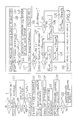
- Fig. 3 is a flow chart according to which the apparatus of Fig. 1 is operated; and
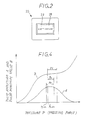
- Fig. 4 is a graph showing a curve representative of change of the pulse amplitudes with respect to the pulse wave sensor pressing forces, and a curve representative of change of the pulse minimum values with respect to the pulse wave sensor pressing forces.
- Referring first to Fig. 1 there is illustrated a pulse wave detecting apparatus embodying the present invention. In the
figure reference numeral 10 designates a cylindrical housing having a bottom end and an open end. Thehousing 10 is detachably set on abody surface 12 of awrist 16 of a subject with the help of aband 14, with the open end of thehousing 10 being opposed to thebody surface 12. Adiaphragm 18 is fluid-tightly secured to inner surfaces of thehousing 10, and cooperates with thehousing 10 to define a fluid-tight pressure chamber 22. Apulse wave sensor 20 for detecting pulse wave is secured to an outer surface of thediaphragm 18. A pressurizedfluid supply 24 supplies thepressure chamber 22 with a pressurized fluid such as pressurized air. Apressure regulating valve 26 regulates the pressurized air supplied to thepressure chamber 22 and thereby adjusts an air pressure P in thepressure chamber 22. As the air pressure P in thepressure chamber 22 is increased or decreased, thediaphragm 18 is inflated or deflated and thepulse wave sensor 20 is displaced together with thediaphragm 18 relative to thehousing 10, so that thepulse wave sensor 20 is advanced out of the open end of thehousing 10 and is pressed against thebody surface 12 with a pressing force corresponding to an air pressure P in thepressure chamber 22. - As shown in Fig. 2 the
pulse wave sensor 20 is constituted by a semiconductor chip formed of, for example, monocrystalline silicon, and a multiplicity ofpressure sensing elements 29, for example fifteen pressure sensing diodes, provided in a row on onesurface 28 of the semiconductor chip. Thus, thechip surface 28 serves as a press surface at which thepulse wave sensor 20 is pressed against thebody surface 12. With thehousing 10 being attached to thewrist 16, the row of thepressure sensing elements 29 extends in a direction generally perpendicular to aradial artery 30 extending adjacent to a radius bone of thewrist 16. In other words, thepulse wave sensor 20 is pressed against theradial artery 30 via thebody surface 12 such that the row of thepressure sensing elements 29 generally perpendicularly intersects theradial artery 30. In this situation, eachpressure sensing element 29 detects an oscillatory pressure wave, namely, pressure pulse wave (hereinafter, abbreviated to "pulse wave") transmitted thereto from theradial artery 30 via thebody surface 12. The pulse wave consists of successive pulses, and the pulses are produced from theradial artery 30 in synchronization with heartbeat of the subject. Each of thepressure sensing elements 29 converts the detected pulse wave to an electric signal (hereinafter, referred to as "pulse wave signal") SM, and supplies the pulse wave signal SM to acontrol device 32. - The
control device 32 includes a microcomputer, and supplies a drive signal SD to thepressure regulating valve 26 according to pre-stored programs so as to adjust the air pressure P in thepressure chamber 22 in thehousing 10. Thecontrol device 32 stores pulse wave signals SM supplied from thepressure sensing elements 29, while commanding thepressure regulating valve 26 to increase the air pressure P at a constant, low rate. Based on the stored pulse wave signals SM thecontrol device 32 selects an optimum pressure sensing element 29A out of the multiplicity ofpressure sensing elements 29 and determines an optimum pressing force Pa with which the pulse wave sensor 20 (optimum pressure sensing element 29A) is to be pressed against theradial artery 30. With thepulse wave sensor 20 being pressed with the optimum pressing force Pa, thecontrol device 32 is supplied with a pulse wave signal SM from the optimum pressure sensing element 29A, and supplies a display/record signal SI representative of the pulse wave, to a display/record device 34. Thus, the display/record device 34 displays and records the pulse wave detected by the optimum pressure sensing element 29A pressed with the optimum pressing force Pa. - There will be described the operation of the pulse wave detecting apparatus constructed as described above, by reference to the flow chart of Fig. 3.
- Upon application of electric power to the present apparatus, the control of the microcomputer of the
control device 32 begins with Step S1 in which it is judged whether or not an ON/OFF switch (not shown) has been operated by an operator, namely, placed in an ON position thereof. If the judgement in Step S1 is negative (NO), Step S1 is repeated awaiting an operation of the ON/OFF switch. On the other hand, if it is judged in Step S1 that the ON/OFF switch is placed in the ON position thereof, namely, if the judgement in Step S1 is affirmative (YES), the control proceeds to Step S2 in which the air pressure P in thepressure chamber 22 is increased at a constant low rate, namely, slowly increased. Step S2 is followed by Step S3 in which it is judged based on the pulse wave signals SM whether or not in this slow pressure increase process thepressure sensing elements 29 have detected a length of pulse wave corresponding to one time heartbeat of the subject, namely, one pulse. If the judgement in Step S3 is negative, Step S3 is repeated. Meanwhile, if the judgement in Step S3 is affirmative, namely, if thepressure sensing elements 29 have detected one pulse of the pulse wave, thecontrol device 32 stores pulse wave signals SM corresponding to the pulse, together with the corresponding values of the air pressure P in thepressure chamber 22. Subsequently, the control proceeds to Step S4 in which it is judged whether or not the air pressure P has exceeded a predetermined pressure level Pa, for example about 200 mmHg. If the judgement in Step S4 is negative, namely, if the air pressure P has not reached the level Pa, Steps S3 and S4 are repeated so that thecontrol device 32 stores the pulse wave signals SM corresponding to a multiplicity of pulses of the pulse wave. On the other hand, if the judgement in Step S4 is affirmative, the control proceeds to Step S5 in which the pressurized air in thepressure chamber 22 is removed to decrease the air pressure P to atmospheric pressure. - Step S5 is followed by Step S6 in which the
control device 32 applies a well-known median filter, a statistical treatment, to the stored pulse wave signals SM with respect to, for example, every five successive pulses of the signals SM, so as to remove artifact noise therefrom, namely, smooth the signals SM. Step S6 is followed by Step S7 in which thecontrol device 32 determines a maximum and a minimum value of each of the pulses with respect to each of the filtered signals SM. Step S7 is followed by Step S8 in which thecontrol device 32 determines an amplitude of each of the pulses based on the maximum and minimum values thereof determined in Step S7. Thus, in the present embodiment Step S7 and a portion of thecontrol device 32 for carrying out Step S7 cooperate with each other to serve as means for determining a minimum value of each of pulses of the pulse wave detected by the pulse wave sensor, while Step S8 and a portion of thecontrol device 32 for carrying out Step S8 cooperate with each other to serve as means for determining an amplitude of each of pulses of the pulse wave detected by the pulse wave sensor. - Subsequently, the control proceeds to Step S9 in which the
control device 32 determines a maximum amplitude with respect to each of the pulse wave signals SM, namely, each of thepressure sensing elements 29. The maximum amplitude is the greatest amplitude of all the amplitudes of the pulses detected by the eachpressure sensing element 29. Step S9 is followed by Step S10 in which thecontrol device 32 selects as an optimum pressure sensing element 29A one of thepressure sensing elements 29 whose maximum amplitude is the greatest of all the maximum amplitudes of thepressure sensing elements 29. Step S10 is followed by Step S11 in which it is judged whether or not either one of the two pressure sensing elements positioned at opposite ends of the row of thepressure sensing elements 29 has been selected as the optimum pressure sensing element 29A. If the judgement in Step S10 is negative, the control proceeds to Step S13. On the other hand, if the judgement is affirmative, the control proceeds to Step S12 in which thecontrol device 32 discards the pressure sensing element selected as the optimum pressure sensing element 29A in Step S11 and re-select as the optimum pressure sensing element 29A another pressure sensing element whose maximum amplitude is the greatest second to the maximum amplitude of the discarded pressure sensing element. Step S12 is followed by Step S13. - In Step S13 the
control device 32 utilizes the amplitudes of the pulses detected by the optimum pressure sensing element 29A in the previously described slow pressure increase process, and the corresponding values of the air pressure P in the pressure chamber 22 (corresponding to pressing forces with which thepulse wave sensor 20 is pressed against the radial artery 30), for determining a first force range in which the pulse amplitudes are generally constant. The first force range includes a point at which the rate of change of the pulse amplitudes with respect to the air pressure values P (corresponding to the pulse wave sensor pressing forces) is zero. This point corresponds to a pressing force at which the optimum pulse wave sensor 29A has detected the pulse having the maximum amplitude. The first force range is determined such that the difference between the maximum pulse amplitude and each of the other pulse amplitudes is smaller than a considerably small value corresponding to, for example 7 mmHg in terms of pressure. The first force range is shown at Pp in the graph of Fig. 4, in which the pulse amplitudes are represented by a curved line A for easy understanding. In the present embodiment Step S13 and a portion of thecontrol device 32 for carrying out Step S13 cooperate with each other to serve as means for determining the first force range of the pulse wave sensor pressing force. - Step S13 is followed by Step S14 in which it is judged whether a value ΔPp obtained by subtracting a lower limit Ppmin of the first force range Pp from an upper limit of the same, is not zero, that is, whether or not the first force range Pp has any length, or exist, along the axis of abscissa of the graph of Fig. 4. If the judgement in Step S14 is negative (NO), namely, if the first force range Pp is zero, that means that a position of the
pulse wave sensor 20 on thebody surface 12 with respect to theradial artery 30 is inappropriate, and the control goes to Step S15 in which thecontrol device 32 commands the display/record device 34 to display a predetermined indication informing the operator of this situation. Step S15 is followed by Step S16 in which thecontrol device 32 causes the ON/OFF switch to be placed in the OFF position, thereby deactivating the present apparatus, and then the control returns to Step S1. However, since the ON/OFF switch has just been placed in the OFF position, the judgement in Step S1 is negative and Step S1 is repeated awaiting for another operation of the ON/OFF switch. - On the other hand, if the judgement in Step S14 is affirmative (YES), that is, if the first force range Pp is not zero, the control goes to Step S17 in which the
control device 32 utilizes the minimum values of the pulses detected by the optimum pressure sensing element 29A, and the corresponding air pressure values P, for determining a second force range in which the pulse minimum values are generally constant. The second force range includes a point at which the rate of change of the pulse minimum values with respect to the air pressure values P is minimum. The second force range is determined such that the difference between a selected one of the pulse minimum values and each of the other pulse minimum values is smaller than a considerably small value corresponding to, for example 7 mmHg in terms of pressure. The second force range is shown at Pd in the graph of Fig. 4, in which the pulse minimum values are represented by a curved line B for easy understanding. In the present embodiment Step S17 and a portion of thecontrol device 32 for carrying out Step S17 cooperate with each other to serve as means for determining the second force range of the pulse wave sensor pressing force. - Step S17 is followed by Step S18 in which it is judged whether a value ΔPd obtained by subtracting a lower limit Pdmin of the second force range Pd from an upper limit of the same, is not zero, that is, whether or not the second force range Pd has any length, or exists, along the axis of abscissa of the graph of Fig. 4. If the judgement in Step S17 is affirmative (YES), that is, if the second force range Pd is not zero, the control advances to Step S19 in which the
control device 32 determines as an optimum force range an overlap portion Pc of the first and second force ranges Pp and Pd. Step S19 is followed by Step S20 in which it is judged whether or not a value ΔPc obtained by subtracting a lower limit Pcmin of the optimum force range Pc from an upper limit of the same is greater than, for example, 100 mmHg. If the judgement in Step S20 is negative, that is, if the value ΔPc is not greater than 100 mmHg, the control goes to Step S21 in which thecontrol device 32 determines an optimum air force Pa corresponding to an optimum, pulse wave sensor pressing force according to the following expression:
control device 32 determines the optimum air force Pa according to the following expression:

- Meanwhile, if the judgement in Step S18 is negative, that is, if the second force range Pd is zero, the
control device 32 determines the first force range Pp as the optimum force range, and the control goes to Step S23 in which it is judged whether or not a value ΔPp obtained by subtracting a lower limit Ppmin of the first force range Pp (optimum force range) from an upper limit of the same, is greater than, for example, 100 mmHg. If the judgement in Step S23 is negative, that is, if the value ΔPc is not greater than 100 mmHg, the control goes to Step S24 in which thecontrol device 32 determines the optimum air force Pa according to the following expression:

control device 32 determines the optimum air force Pa according to the following expression:
- In the present embodiment Steps S18 through S25 and a portion of the
control device 32 for carrying out Steps S18-S25 cooperate with each other to serve as means for determining an optimum force range of the pulse wave sensor pressing force based on the first and second force ranges, and determining an optimum value of the pressing force such that the optimum value falls within the optimum force range. - After the determination of the optimum air pressure Pa (optimum value of the pulse wave sensor pressing force) in Step S21, S22, S24 or S25, the control goes to Step S26 in which the
control device 32 controls thepressure regulating valve 26 to increase the air pressure P in thepressure chamber 22 to the optimum air pressure Pa and hold the air pressure Pa. As a result, thepulse wave sensor 20 is pressed against theradial artery 30 with an optimum pressing force corresponding to the optimum air pressure Pa. With thepulse wave sensor 20 being pressed with the optimum pressing force (Pa), the present apparatus obtains a pulse wave of the subject through the optimum pressure sensing element 29A, and commands the display/record device 34 to display and record the thus obtained pulse wave. Thecontrol device 32 may be adapted to determine a blood pressure of the subject based on the thus obtained pulse wave and command the display/record device 34 to display and record the thus determined blood pressure. - As emerges from the foregoing description, the present pulse wave detecting apparatus utilizes a pulse wave (pulses thereof) which is detected by the optimum pressure sensing element 29A as the pulse wave sensor pressing force is increased at a constant low rate, for determining the first force range Pp within which the pulse amplitudes are generally constant and which includes a pressing force at which the optimum pressure sensing element 29A has detected the pulse having the maximum amplitude. In addition, the present apparatus determines the second force range Pd within which the pulse minimum values are generally constant. In Step S19 of the flow chart of Fig. 3 the overlap portion Pc of the first and second force ranges Pp and Pd is determined as the optimum force range. So long as the
pulse wave sensor 20 is pressed with a pressing force falling within the optimum force range, thepulse wave sensor 20 detects a pulse wave having a sufficiently great amplitude. In Step S21 the middle value of the overlap portion Pc is determined as the optimum pulse wave sensor pressing force Pa. Therefore, the optimum pressing force Pa falls between the middle value of the first force range Pp and the middle value of the second force range Pd. Thus, even if the pulse wave sensor pressing force is changed due to physical motion of the subject or the like during the pulse wave detection, the present apparatus continues to detect a pulse wave having a sufficiently great amplitude. - In the present embodiment, in Step S20 it is judged whether or not a difference ΔPc between an upper and a lower limit of the overlap portion Pc is greater than 100 mmHg, and if the judgement in Step S20 is affirmative a value obtained by adding 50 mmHg to the lower limit Pcmin is used as the optimum pressing force Pa. This optimum pressing force Pa is smaller than the middle value of the overlap portion Pc. Thus, in the event that the overlap portion Pc is considerably wide, the present apparatus determines the optimum pressing force Pa at a relatively low value and thereby reduces discomfort of the subject due to the pressed
pulse wave sensor 20. - Although in the graph of Fig. 4 the second force range Pd overlaps an upper portion of the first force range Pp, the second force range Pd may overlap a lower portion of the first force range Pd. In the latter case, the optimum pressing force Pa is determined at a value smaller than a pressing force at which the optimum pressure sensing element 29A has detected the maximum pulse amplitude. Thus, the present apparatus uses the optimum pressing force Pa smaller than an optimum pressing force that has conventionally been used by the known apparatus in which a pressing force at the time of detection of the maximum pulse amplitude is used as the optimum pressing force.
- In the present embodiment, in Step S18 it is judged whether the second force range Pd is not zero. This is why there are some cases where the second force range Pd is zero, namely, the minimum values of the pulses detected by the optimum pressure sensing element 29A have no range within which differences between the pulse minimum values are smaller than a predetermined considerably small value. In those cases the first force range Pp is determined as the optimum force range, and the optimum pressing force Pa is determined based on the first force range Pp only. Thus, in the event that the first force range Pp is not zero, the apparatus does not fail to detect a pulse wave, even if the second force range Pd is zero.
- In addition, in the present embodiment, in Step S14 it is judged whether the first force range Pp is not zero, and if the judgement is negative (NO), namely, if the first force range Pp is zero, in Step S15 the indication informing that the position of pressing of the
pulse wave sensor 20 with respect to theradial artery 30 is inappropriate, is displayed on the display/record device 34, and in Step S16 the ON/OFF switch (not shown) is placed in the OFF position to deactivate the apparatus. Thus, the apparatus easily judges whether or not thepulse wave sensor 20 is appropriately positioned on thebody surface 12 with respect to theradial artery 30. In other words, the present apparatus prevents thepulse wave sensor 20 from being located on thebody surface 12 at an inappropriate position where the amplitude of pulse wave detected by thepulse wave sensor 20 is relatively largely changed due to a relatively small change in the pulse wave sensor pressing force. - Since in the present embodiment the pulses detected by the pulse wave sensor 20 (pressure sensing elements 29) are subjected to the median filter treatment, the first and second force ranges Pp and Pd are determined with high precision, and accordingly the optimum pressing force pa is determined in a reliable manner.
- While the present invention has been described in its presently preferred embodiment, it is to be understood that the present invention is by no means limited to the particular details of the embodiment but may be otherwise embodied.
- For example, in the event that it is judged in Step S20 of the flow chart of Fig. 3 that the value ΔPc is greater than 100 mmHg, it is possible to judge in an additional step whether or not the value ΔPc is greater than another predetermined value greater than 100 mmHg and determine the optimum pressing force Pa in each of the respective ways corresponding to the affirmative and negative judgements in the additional step. Alternatively, Steps S20 and S22 may be omitted, namely, the middle value of the overlap portion Pc may be determined as the optimum pressing force Pa irrespective of the value ΔPc.
- Although, in the illustrated embodiment, in Step S22 or S25 the optimum pressing force Pa is determined by adding 50 mmHg, one second of 100 mmHg, to the minimum value Pcmin or Ppmin of the overlap portion Pc or first force range Pp, respectively, it is possible to add a value greater or smaller than 50 mmHg to the minimum value Pcmin or Ppmin.
- Furthermore, in the event that the second force range Pd is zero, it is possible to effect additional steps similar to Steps S15 and S16 provided for the event that the first force range Pp is zero.
- Although in the illustrated embodiment the optimum pressing force Pa is determined based on the pulse wave signals SM which are produced as the air pressure P in the
pressure chamber 22 is increased, it is possible to use pulse wave signals SM which are produced as the air pressure P is decreased, for the determination of the optimum pressing force Pa. - The multiplicity of
pressure sensing elements 29 may be replaced by a single pressure sensing element. In addition, the individualpressure sensing elements 29 may be constituted by various elements different from the diodes or other pressure sensing semiconductor elements. - While in the illustrated embodiment the
pulse wave sensor 20 is adapted to be pressed against theradial artery 30, it is possible to use a pulse wave sensor adapted to be pressed against an arterial vessel different from theradial artery 30, such as dorsal pedal artery. - It is to be understood that the present invention may be modified with other changes, improvements and modifications that may occur to those skilled in the art without departing from the spirit and scope of the present invention defined in the appended claims.
Claims (12)
- A pulse wave detecting apparatus for detecting a pulse wave produced from an arterial vessel of a subject, comprising:
a pulse wave sensor (20) having a press surface (28) on which at least one pressure sensing element (29) is provided, said pulse wave sensor to be pressed against an arterial vessel (30) of a subject (16) via a body surface (12) above said arterial vessel so that said at least one pressure sensing element detects a pulse wave produced from said arterial vessel of said subject;
pressing means (10, 18, 22-26, 32) for pressing said pulse wave sensor against said arterial vessel via said body surface, while varying the pressing force over a predetermined force range;
first means (32, S8) for determining the amplitude of each of the pulses of the pulse wave which are detected by said at least one pressure sensing element while the pressing force of said pressing means is varied;
second means (32, S9-S13) for determining, based on the pulse amplitudes determined by said first means, a first force range (Pp) of said pressing force within which said pulse amplitudes are generally constant, said first force range including a point at which a rate of change of said pulse amplitudes with respect to said pressing force is zero;
third means (32, S7) for determining a minimum value of said each pulse of the pulse wave detected by said at least one pressure sensing element;
fourth means (32, S17) for determining, based on the pulse minimum values determined by said third means, a second force range (Pd) of said pressing force within which said pulse minimum values are generally constant, said second force range including a point at which a rate of change of said pulse minimum values with respect to said pressing force is minimum;
fifth means (32, S18-S25) for determining an optimum force range (Pc, Pp) of said pressing force based on said first and second force ranges, and determining an optimum value (PA) of said pressing force such that said optimum value falls within said optimum force range; and
sixth means (32, S26) for adjusting said pressing means to said optimum value of said pressing force, and obtaining a pulse wave of said subject through said pulse wave sensor pressed against said arterial vessel with the optimum pressing force. - The apparatus as set forth in claim 1, wherein, in the event that neither said first force range (Pp) nor said second force range (Pd) is zero, said fifth means determines as said optimum force range an overlap portion (Pc) of said first and second force ranges.
- The apparatus as set forth in claim 2, wherein, in the event that a value ΔPc obtained by subtracting a lower limit Pcmin of said overlap potion (Pc) from an upper limit thereof is smaller than a first predetermined value S, said fifth means (32, S18-S25) determines said optimum pressing force Pa according to the following expression:


- The apparatus as set forth in any preceding claim wherein, in the event that said first force range (Pp) is not zero and said second force range (Pd) is zero, said fifth means (32, S18-S25) determines said first force range as said optimum force range.
- The apparatus as set forth in claim 4, wherein, in the event that a value ΔPp obtained by subtracting a lower limit Ppmin of said first force range from an upper limit thereof is smaller than a second predetermined value T, said fifth means (32, S18-S25) determines said optimum value Pa of the pressing force according to the following expression:


- The apparatus as set forth in any preceding claim further comprising
means (32, S14-S16) for, in the event that said first force range (Pp) is zero, informing an operator that a position of said pulse wave sensor (20) on said body surface (12) with respect to said arterial vessel (30) is inappropriate, and causing the pulse wave detecting apparatus to be deactivated. - The apparatus as set forth in any preceding claim wherein said pressing means comprises:
a housing (10);
a diaphragm (18) fluid-tightly secured to inner surfaces of said housing, said diaphragm cooperating with said housing to define a fluid-tight pressure chamber (22), said pulse wave sensor (20) being secured to an outer surface of said diaphragm so that said pulse wave sensor is movable together with said diaphragm relative to said housing;
supply means (24) for supplying said pressure chamber with a pressurized fluid so as to press said pulse wave sensor against said arterial vessel (30) via said body surface (12); and
pressure regulating means (26) for regulating said pressurized fluid supplied to said pressure chamber and thereby adjusting a fluid pressure in said pressure chamber,
said pressing force of said pressing means with which said pulse wave sensor is pressed against said arterial vessel being varied as said fluid pressure in said pressure chamber is varied by said pressure regulating means. - The apparatus as set forth in any preceding claim wherein said pulse wave sensor (20) comprises:
a semiconductor chip (28) of monocrystalline silicon; and
a plurality of pressure sensing diodes (29) provided in a row on one surface (28) of said semiconductor chip, said one surface of said semiconductor chip serving as said press surface of said pulse wave sensor, each of said plurality of pressure sensing diodes detecting a pulse wave produced from said arterial vessel (30). - The apparatus as set forth in any preceding claim wherein said at least one pressure sensing element comprise a plurality of pressure sensing elements (29), and wherein (a) said first means (32, S8) determines an amplitude of each of pulses of the pulse wave which are detected by each of said plurality of pressure sensing elements while said pressing force of said pressing means (10, 18, 22-26, 32) is varied, (b) said second means (32, S9-S13) selects as an optimum pressure sensing element (29A) one of said plurality of pressure sensing elements which element has detected a pulse whose amplitude is the greatest of the amplitudes of the pulses detected by said plurality of pressure sensing elements, and determines said first force range (Pp) based on the amplitudes of the pulses detected by said optimum pressure sensing element, (c) said third means (32, S7) determines an minimum value of each of the pulses detected by said optimum pressure sensing element, and (d) said fourth means (32, S17) determines said second force range (Pd) based on the pulse minimum values determined by said third means.
- The apparatus as set forth in claim 9, wherein said plurality of pressure sensing elements comprise at least three pressure sensing elements (29) provided in a row on said press surface (28) of said pulse wave sensor (20),
the apparatus further comprising
means (32, S14-S16) for, in the event that said second means (32, S9-S13) selects as said optimum pressure sensing element one of two pressure sensing elements respectively positioned at opposite ends of said row, discarding the pressure sensing element selected by said second means, and re-selecting as said optimum pressure sensing element (29A) another pressure sensing element which has detected a pulse whose amplitude is the greatest of the amplitudes of the pulses detected by said at least three pressure sensing elements except the discarded pressure sensing element. - The apparatus as set forth in any preceding claim further comprising
means (34) for displaying and recording said pulse wave detected through said pulse wave sensor (20) pressed with said optimum pressing force. - The apparatus as set forth in any preceding claim further comprising
means (32) for determining a blood pressure of said subject based on said pulse wave detected through said pulse wave sensor (20) pressed with said optimum pressing force.
Priority Applications (2)
| Application Number | Priority Date | Filing Date | Title |
|---|---|---|---|
| EP19900304161 EP0452578B1 (en) | 1990-04-18 | 1990-04-18 | Pulse wave detecting apparatus |
| DE1990617892 DE69017892T2 (en) | 1990-04-18 | 1990-04-18 | Pulse wave measuring device. |
Applications Claiming Priority (1)
| Application Number | Priority Date | Filing Date | Title |
|---|---|---|---|
| EP19900304161 EP0452578B1 (en) | 1990-04-18 | 1990-04-18 | Pulse wave detecting apparatus |
Publications (2)
| Publication Number | Publication Date |
|---|---|
| EP0452578A1 true EP0452578A1 (en) | 1991-10-23 |
| EP0452578B1 EP0452578B1 (en) | 1995-03-15 |
Family
ID=8205383
Family Applications (1)
| Application Number | Title | Priority Date | Filing Date |
|---|---|---|---|
| EP19900304161 Expired - Lifetime EP0452578B1 (en) | 1990-04-18 | 1990-04-18 | Pulse wave detecting apparatus |
Country Status (2)
| Country | Link |
|---|---|
| EP (1) | EP0452578B1 (en) |
| DE (1) | DE69017892T2 (en) |
Cited By (5)
| Publication number | Priority date | Publication date | Assignee | Title |
|---|---|---|---|---|
| EP0671144A1 (en) * | 1994-03-09 | 1995-09-13 | Colin Corporation | Pulse wave detecting apparatus |
| US5497779A (en) * | 1994-03-08 | 1996-03-12 | Colin Corporation | Pulse wave detecting apparatus |
| US6616612B1 (en) | 1999-03-12 | 2003-09-09 | Polar Electro Oy | Measuring arrangement |
| CN102302360A (en) * | 2011-07-21 | 2012-01-04 | 邵光震 | Pulse signal automatic extraction device and extraction method thereof |
| TWI478693B (en) * | 2011-07-21 | 2015-04-01 |
Citations (3)
| Publication number | Priority date | Publication date | Assignee | Title |
|---|---|---|---|---|
| WO1988003387A1 (en) * | 1986-11-06 | 1988-05-19 | Sri International | Blood pressure monitoring method and apparatus |
| US4836213A (en) * | 1988-02-25 | 1989-06-06 | Nippon Colin Co., Ltd. | Pressure control system for continuous blood pressure monitor transducer |
| JPH02109540A (en) * | 1988-10-19 | 1990-04-23 | Koorin Denshi Kk | Pulse wave detector |
-
1990
- 1990-04-18 EP EP19900304161 patent/EP0452578B1/en not_active Expired - Lifetime
- 1990-04-18 DE DE1990617892 patent/DE69017892T2/en not_active Expired - Fee Related
Patent Citations (3)
| Publication number | Priority date | Publication date | Assignee | Title |
|---|---|---|---|---|
| WO1988003387A1 (en) * | 1986-11-06 | 1988-05-19 | Sri International | Blood pressure monitoring method and apparatus |
| US4836213A (en) * | 1988-02-25 | 1989-06-06 | Nippon Colin Co., Ltd. | Pressure control system for continuous blood pressure monitor transducer |
| JPH02109540A (en) * | 1988-10-19 | 1990-04-23 | Koorin Denshi Kk | Pulse wave detector |
Cited By (6)
| Publication number | Priority date | Publication date | Assignee | Title |
|---|---|---|---|---|
| US5497779A (en) * | 1994-03-08 | 1996-03-12 | Colin Corporation | Pulse wave detecting apparatus |
| EP0671144A1 (en) * | 1994-03-09 | 1995-09-13 | Colin Corporation | Pulse wave detecting apparatus |
| US6616612B1 (en) | 1999-03-12 | 2003-09-09 | Polar Electro Oy | Measuring arrangement |
| CN102302360A (en) * | 2011-07-21 | 2012-01-04 | 邵光震 | Pulse signal automatic extraction device and extraction method thereof |
| TWI478692B (en) * | 2011-07-21 | 2015-04-01 | ||
| TWI478693B (en) * | 2011-07-21 | 2015-04-01 |
Also Published As
| Publication number | Publication date |
|---|---|
| DE69017892T2 (en) | 1995-08-03 |
| EP0452578B1 (en) | 1995-03-15 |
| DE69017892D1 (en) | 1995-04-20 |
Similar Documents
| Publication | Publication Date | Title |
|---|---|---|
| US5119822A (en) | Pulse wave detecting apparatus | |
| US5033471A (en) | Method and apparatus measuring blood pressure | |
| US5103831A (en) | Pulse wave detecting apparatus | |
| US5261414A (en) | Blood pressure monitor system | |
| US5140991A (en) | Heartbeat synchronous pulse wave detecting apparatus | |
| US5762610A (en) | Pressure pulse wave detecting apparatus | |
| CA1331788C (en) | Blood pressure monitoring system | |
| US5119824A (en) | Heartbeat synchronous wave detecting apparatus | |
| US6869403B2 (en) | Blood-pressure determining apparatus | |
| US6645156B2 (en) | Continuous blood-pressure monitoring apparatus | |
| EP0510720A2 (en) | Method and apparatus for monitoring blood pressure | |
| EP0651969B1 (en) | Blood pressure monitor system | |
| US5139026A (en) | Pulse wave detecting apparatus and pulse wave detecting method | |
| EP0838194B1 (en) | Physical information monitor system having means for indicating amount of deviation of monitored information from normal information | |
| US5752913A (en) | Physical information monitor system having means for determining reference range for abnormality determination of the monitored information | |
| US5031630A (en) | Automatic blood pressure measuring apparatus | |
| EP0452578B1 (en) | Pulse wave detecting apparatus | |
| US5590661A (en) | Blood pressure measuring apparatus | |
| EP0333449A1 (en) | Method and apparatus for detecting pulse wave | |
| US4917098A (en) | Method and apparatus for measuring blood pressure | |
| JPH082351B2 (en) | Pulse wave detector | |
| JPH1119054A (en) | Pressing-correcting type continuous blood pressure monitoring device | |
| JPH037139A (en) | Pulse wave sensing device | |
| JPH0434808Y2 (en) | ||
| EP0671144B1 (en) | Pulse wave detecting apparatus |
Legal Events
| Date | Code | Title | Description |
|---|---|---|---|
| PUAI | Public reference made under article 153(3) epc to a published international application that has entered the european phase |
Free format text: ORIGINAL CODE: 0009012 |
|
| AK | Designated contracting states |
Kind code of ref document: A1 Designated state(s): DE FR GB IT NL SE |
|
| 17P | Request for examination filed |
Effective date: 19911111 |
|
| 17Q | First examination report despatched |
Effective date: 19930909 |
|
| RAP1 | Party data changed (applicant data changed or rights of an application transferred) |
Owner name: COLIN CORPORATION |
|
| GRAA | (expected) grant |
Free format text: ORIGINAL CODE: 0009210 |
|
| AK | Designated contracting states |
Kind code of ref document: B1 Designated state(s): DE FR GB IT NL SE |
|
| PG25 | Lapsed in a contracting state [announced via postgrant information from national office to epo] |
Ref country code: IT Free format text: LAPSE BECAUSE OF FAILURE TO SUBMIT A TRANSLATION OF THE DESCRIPTION OR TO PAY THE FEE WITHIN THE PRE;WARNING: LAPSES OF ITALIAN PATENTS WITH EFFECTIVE DATE BEFORE 2007 MAY HAVE OCCURRED AT ANY TIME BEFORE 2007. THE CORRECT EFFECTIVE DATE MAY BE DIFFERENT FROM THE ONE RECORDED.SCRIBED TIME-LIMIT Effective date: 19950315 Ref country code: NL Free format text: LAPSE BECAUSE OF NON-PAYMENT OF DUE FEES Effective date: 19950315 |
|
| REF | Corresponds to: |
Ref document number: 69017892 Country of ref document: DE Date of ref document: 19950420 |
|
| ET | Fr: translation filed | ||
| PG25 | Lapsed in a contracting state [announced via postgrant information from national office to epo] |
Ref country code: SE Effective date: 19950615 |
|
| NLV1 | Nl: lapsed or annulled due to failure to fulfill the requirements of art. 29p and 29m of the patents act | ||
| PLBE | No opposition filed within time limit |
Free format text: ORIGINAL CODE: 0009261 |
|
| STAA | Information on the status of an ep patent application or granted ep patent |
Free format text: STATUS: NO OPPOSITION FILED WITHIN TIME LIMIT |
|
| 26N | No opposition filed | ||
| REG | Reference to a national code |
Ref country code: GB Ref legal event code: IF02 |
|
| PGFP | Annual fee paid to national office [announced via postgrant information from national office to epo] |
Ref country code: FR Payment date: 20030408 Year of fee payment: 14 |
|
| PGFP | Annual fee paid to national office [announced via postgrant information from national office to epo] |
Ref country code: GB Payment date: 20030416 Year of fee payment: 14 |
|
| PGFP | Annual fee paid to national office [announced via postgrant information from national office to epo] |
Ref country code: DE Payment date: 20030502 Year of fee payment: 14 |
|
| REG | Reference to a national code |
Ref country code: GB Ref legal event code: 732E |
|
| PG25 | Lapsed in a contracting state [announced via postgrant information from national office to epo] |
Ref country code: GB Free format text: LAPSE BECAUSE OF NON-PAYMENT OF DUE FEES Effective date: 20040418 |
|
| PG25 | Lapsed in a contracting state [announced via postgrant information from national office to epo] |
Ref country code: DE Free format text: LAPSE BECAUSE OF NON-PAYMENT OF DUE FEES Effective date: 20041103 |
|
| GBPC | Gb: european patent ceased through non-payment of renewal fee |
Effective date: 20040418 |
|
| PG25 | Lapsed in a contracting state [announced via postgrant information from national office to epo] |
Ref country code: FR Free format text: LAPSE BECAUSE OF NON-PAYMENT OF DUE FEES Effective date: 20041231 |
|
| REG | Reference to a national code |
Ref country code: FR Ref legal event code: ST |