EP0452574B1 - Improved contacting between plural distinct fluid phases contained in a vertically disposed vessel - Google Patents
Improved contacting between plural distinct fluid phases contained in a vertically disposed vessel Download PDFInfo
- Publication number
- EP0452574B1 EP0452574B1 EP90304114A EP90304114A EP0452574B1 EP 0452574 B1 EP0452574 B1 EP 0452574B1 EP 90304114 A EP90304114 A EP 90304114A EP 90304114 A EP90304114 A EP 90304114A EP 0452574 B1 EP0452574 B1 EP 0452574B1
- Authority
- EP
- European Patent Office
- Prior art keywords
- vessel
- fluid
- phases
- distinct
- liquid
- Prior art date
- Legal status (The legal status is an assumption and is not a legal conclusion. Google has not performed a legal analysis and makes no representation as to the accuracy of the status listed.)
- Expired - Lifetime
Links
- 239000012530 fluid Substances 0.000 title claims abstract description 41
- 238000000034 method Methods 0.000 claims abstract description 11
- 239000012071 phase Substances 0.000 claims description 21
- QAOWNCQODCNURD-UHFFFAOYSA-N sulfuric acid group Chemical group S(O)(O)(=O)=O QAOWNCQODCNURD-UHFFFAOYSA-N 0.000 claims description 12
- 150000001336 alkenes Chemical class 0.000 claims description 8
- 239000007791 liquid phase Substances 0.000 claims description 7
- JRZJOMJEPLMPRA-UHFFFAOYSA-N olefin Natural products CCCCCCCC=C JRZJOMJEPLMPRA-UHFFFAOYSA-N 0.000 claims description 6
- 239000007792 gaseous phase Substances 0.000 claims description 3
- 239000007788 liquid Substances 0.000 description 20
- 239000007789 gas Substances 0.000 description 14
- 239000000203 mixture Substances 0.000 description 4
- 238000006243 chemical reaction Methods 0.000 description 3
- 239000012263 liquid product Substances 0.000 description 2
- VXNZUUAINFGPBY-UHFFFAOYSA-N 1-Butene Chemical compound CCC=C VXNZUUAINFGPBY-UHFFFAOYSA-N 0.000 description 1
- 238000010521 absorption reaction Methods 0.000 description 1
- 239000002253 acid Substances 0.000 description 1
- 150000001298 alcohols Chemical class 0.000 description 1
- IAQRGUVFOMOMEM-UHFFFAOYSA-N butene Natural products CC=CC IAQRGUVFOMOMEM-UHFFFAOYSA-N 0.000 description 1
- 238000001311 chemical methods and process Methods 0.000 description 1
- 238000004581 coalescence Methods 0.000 description 1
- 239000006185 dispersion Substances 0.000 description 1
- 235000012489 doughnuts Nutrition 0.000 description 1
- 230000036571 hydration Effects 0.000 description 1
- 238000006703 hydration reaction Methods 0.000 description 1
- 230000004048 modification Effects 0.000 description 1
- 238000012986 modification Methods 0.000 description 1
- QQONPFPTGQHPMA-UHFFFAOYSA-N propylene Natural products CC=C QQONPFPTGQHPMA-UHFFFAOYSA-N 0.000 description 1
- 125000004805 propylene group Chemical group [H]C([H])([H])C([H])([*:1])C([H])([H])[*:2] 0.000 description 1
- 230000003134 recirculating effect Effects 0.000 description 1
- 238000004513 sizing Methods 0.000 description 1
- 239000000126 substance Substances 0.000 description 1
- 230000007306 turnover Effects 0.000 description 1
Images
Classifications
-
- B—PERFORMING OPERATIONS; TRANSPORTING
- B01—PHYSICAL OR CHEMICAL PROCESSES OR APPARATUS IN GENERAL
- B01J—CHEMICAL OR PHYSICAL PROCESSES, e.g. CATALYSIS OR COLLOID CHEMISTRY; THEIR RELEVANT APPARATUS
- B01J19/00—Chemical, physical or physico-chemical processes in general; Their relevant apparatus
- B01J19/24—Stationary reactors without moving elements inside
- B01J19/2455—Stationary reactors without moving elements inside provoking a loop type movement of the reactants
- B01J19/246—Stationary reactors without moving elements inside provoking a loop type movement of the reactants internally, i.e. the mixture circulating inside the vessel such that the upward stream is separated physically from the downward stream(s)
-
- B—PERFORMING OPERATIONS; TRANSPORTING
- B01—PHYSICAL OR CHEMICAL PROCESSES OR APPARATUS IN GENERAL
- B01F—MIXING, e.g. DISSOLVING, EMULSIFYING OR DISPERSING
- B01F23/00—Mixing according to the phases to be mixed, e.g. dispersing or emulsifying
- B01F23/20—Mixing gases with liquids
- B01F23/23—Mixing gases with liquids by introducing gases into liquid media, e.g. for producing aerated liquids
- B01F23/231—Mixing gases with liquids by introducing gases into liquid media, e.g. for producing aerated liquids by bubbling
-
- B—PERFORMING OPERATIONS; TRANSPORTING
- B01—PHYSICAL OR CHEMICAL PROCESSES OR APPARATUS IN GENERAL
- B01J—CHEMICAL OR PHYSICAL PROCESSES, e.g. CATALYSIS OR COLLOID CHEMISTRY; THEIR RELEVANT APPARATUS
- B01J19/00—Chemical, physical or physico-chemical processes in general; Their relevant apparatus
- B01J19/24—Stationary reactors without moving elements inside
- B01J19/2455—Stationary reactors without moving elements inside provoking a loop type movement of the reactants
- B01J19/2465—Stationary reactors without moving elements inside provoking a loop type movement of the reactants externally, i.e. the mixture leaving the vessel and subsequently re-entering it
-
- B—PERFORMING OPERATIONS; TRANSPORTING
- B01—PHYSICAL OR CHEMICAL PROCESSES OR APPARATUS IN GENERAL
- B01J—CHEMICAL OR PHYSICAL PROCESSES, e.g. CATALYSIS OR COLLOID CHEMISTRY; THEIR RELEVANT APPARATUS
- B01J19/00—Chemical, physical or physico-chemical processes in general; Their relevant apparatus
- B01J19/26—Nozzle-type reactors, i.e. the distribution of the initial reactants within the reactor is effected by their introduction or injection through nozzles
-
- C—CHEMISTRY; METALLURGY
- C07—ORGANIC CHEMISTRY
- C07C—ACYCLIC OR CARBOCYCLIC COMPOUNDS
- C07C29/00—Preparation of compounds having hydroxy or O-metal groups bound to a carbon atom not belonging to a six-membered aromatic ring
- C07C29/03—Preparation of compounds having hydroxy or O-metal groups bound to a carbon atom not belonging to a six-membered aromatic ring by addition of hydroxy groups to unsaturated carbon-to-carbon bonds, e.g. with the aid of H2O2
- C07C29/04—Preparation of compounds having hydroxy or O-metal groups bound to a carbon atom not belonging to a six-membered aromatic ring by addition of hydroxy groups to unsaturated carbon-to-carbon bonds, e.g. with the aid of H2O2 by hydration of carbon-to-carbon double bonds
- C07C29/05—Preparation of compounds having hydroxy or O-metal groups bound to a carbon atom not belonging to a six-membered aromatic ring by addition of hydroxy groups to unsaturated carbon-to-carbon bonds, e.g. with the aid of H2O2 by hydration of carbon-to-carbon double bonds with formation of absorption products in mineral acids and their hydrolysis
- C07C29/06—Preparation of compounds having hydroxy or O-metal groups bound to a carbon atom not belonging to a six-membered aromatic ring by addition of hydroxy groups to unsaturated carbon-to-carbon bonds, e.g. with the aid of H2O2 by hydration of carbon-to-carbon double bonds with formation of absorption products in mineral acids and their hydrolysis the acid being sulfuric acid
-
- B—PERFORMING OPERATIONS; TRANSPORTING
- B01—PHYSICAL OR CHEMICAL PROCESSES OR APPARATUS IN GENERAL
- B01J—CHEMICAL OR PHYSICAL PROCESSES, e.g. CATALYSIS OR COLLOID CHEMISTRY; THEIR RELEVANT APPARATUS
- B01J2219/00—Chemical, physical or physico-chemical processes in general; Their relevant apparatus
- B01J2219/00761—Details of the reactor
- B01J2219/00763—Baffles
- B01J2219/00765—Baffles attached to the reactor wall
- B01J2219/00777—Baffles attached to the reactor wall horizontal
-
- Y—GENERAL TAGGING OF NEW TECHNOLOGICAL DEVELOPMENTS; GENERAL TAGGING OF CROSS-SECTIONAL TECHNOLOGIES SPANNING OVER SEVERAL SECTIONS OF THE IPC; TECHNICAL SUBJECTS COVERED BY FORMER USPC CROSS-REFERENCE ART COLLECTIONS [XRACs] AND DIGESTS
- Y10—TECHNICAL SUBJECTS COVERED BY FORMER USPC
- Y10S—TECHNICAL SUBJECTS COVERED BY FORMER USPC CROSS-REFERENCE ART COLLECTIONS [XRACs] AND DIGESTS
- Y10S261/00—Gas and liquid contact apparatus
- Y10S261/75—Flowing liquid aspirates gas
Definitions
- the present invention is concerned with improvements in contacting distinct, physical phases such as gases and liquids.
- a problem addressed by the present invention is to provide improvements in contacting of plural, distinct phases so as to enhance or improve the chemical processes being conducted.
- Another problem which the present invention can be used to solve is to provide improvements in absorption and reaction of olefins, either gases or liquids, by sulfuric acid in the hydration of olefins to produce alcohols.
- a method for improving the contacting of plural, distinct fluid phases comprising at least a first liquid phase and a second liquid or gaseous phase, contained in a vertically disposed vessel, said vessel being devoid of any upright cylindrical circulation tube disposed inside the vessel below the level of the fluid therein, said method comprising: injecting a stream of dispersed distinct fluid phases together into the fluid contained in the vessel at a location below the fluid level to form bubbles or droplets of said second phase in the fluid, said stream being injected at a velocity which is at least three times the buoyant rise velocity of the largest bubble or droplet in the vessel and with an angle of ejection such that at its maximum downward travel the injected fluid phases flow outwardly for a distance between .4 to .7 times the transverse dimension of the vessel, whereby the fluid in the vessel and the injected fluid are forced to flow downwardly through the central region of the vessel and upwardly in an annular region surrounding the central region, so that the dispersed phases are circulated and contacted.
- FIG. 1 there is shown a generally cylindrical, vertically disposed vessel 10 having sidewalls 11 and top and bottom walls 12 and 14, respectively.
- Vessel 10 is also provided with a conduit 4 for removal of liquids for recycle via lines 5 and 6.
- a conduit 2 is provided for introduction of liquids recycled via lines 5 and 6.
- Vessel 10 is also equipped with a conduit 3 for removal of liquid product for delivery, for example, to a liquid product store (not shown).
- Line 8 is provided connecting a gaseous olefin source (not shown) with recycle line 6.
- a gaseous olefin and sulfuric acid may be fed together via conduit 2 into the vessel 10.
- Conduit 2 contains disk and donut baffles, 18 and 19, respectively, for turning and mixing the gaseous olefin and liquid sulfuric acid as it passes through conduit 2.
- the mixture of gas and liquid then passes into a pipe 21 centrally positioned in a cylindrical mixing vessel 22.
- pipe 21 has a plurality of holes 23 for further mixing of the gas and liquid.
- the fluid then exits the mixing vessel 22 and flows into a nozzle 24 which opens below the level of liquid 20 in the vessel 10.
- the nozzle 24 is designed to direct the flow of dispersed gas and liquid phases downwardly substantially in the central region of the vessel.
- the flow of dispersed phases ejected from the nozzle will flow outwardly as well as downwardly as shown by the dotted lines.
- the angle at which the dispersed phases are ejected from nozzle 24 will depend upon a number of factors such as the ratio of the length to diameter of the vessel. In general, however, the angle of ejection of dispersed fluid phases from nozzle 24 will be such that the fluid at its maximum length of downward travel will flow outwardly for a distance between .4 to .7 times the diameter of vessel 10.
- the diameter of the nozzle is sufficient to transfer enough momentum from fluid ejected from the nozzle to fluid in its flow path to move from about 3 to about 20 times the amount of fluid ejected. This can be achieved by sizing the nozzle diameter to be from about 1/12 to about 1/20 the length of the vessel.
- baffle 17 for directing the flow of dispersed fluid radially outwardly.
- This baffle is positioned substantially normal to the downward flow of fluid ejected from nozzle 24 and placed near the bottom of the vessel. Indeed, it is preferred that the baffle has a diameter of from about 0.4 to about 0.7 times the diameter of the vessel and that it be located at a distance from the vessel bottom that is about 0.2 to about 0.5 times the diameter of the vessel.
- the vessel 10 is devoid of any upright cylindrical circulation tube disposed inside the vessel 10 between the baffle 17 and the surface of the liquid inside the vessel.
- a mixture of the olefin and sulfuric acid is churned and mixed by the baffles in the conduit 2 and fed through holes 23 of pipe 21 causing extremely small bubbles to be formed.
- the gas and liquid mixture then is emitted as a jet of fluid from nozzle 24 and is injected into the fluid contained in the vessel.
- the jet of fluid exiting the nozzle exchanges its momentum with the fluid in the central region 15 of the vessel especially the fluid directly in its conical flow path, and causes the fluid in this region to move in substantially a downwardly direction but also in an outwardly direction. This movement in turn causes the entire contents of the vessel to move.
- This fluid moves upwardly in the annular region 16 between the side walls 11 and the central region 15.
- baffle 17 deflects the jet energy of the fluids flowing downwardly, and deflects them radially outwardly preventing the energy from leaving through the recycle exit conduit 4.
- recycle flows are adjusted to give five turnovers of fluid within the vessel or an axial liquid velocity within the vessel which is at least three times, for example, from three to five times, the buoyant rise velocity of the largest bubble in the vessel. This results in an extremely high vapor holdup of small bubbles formed by the holes 23 of pipe 21 and the nozzle 24. Furthermore, by maintaining a high recirculation rate within the vessel, bubble coalescence can be reduced with the concomitant result that the high interfacial areas that are generated by the holes 23 in mixer 22 are maintained.
- ring sparger pipes 26 and 27 are located at the lower end of the annular region 16 of vessel 10.
- the spargers are located in the annular region 16 sufficiently above baffle 17 so as not to interfere with the downward flow of fluid from central region 15.
- a portion of the gaseous olefin is sparged through the annular ring sparger 26 from line 28 to aid in setting up and maintaining the flow of fluids circulating in vessel 10.
- a portion of the liquid acid is sparged through ring spargers 27 from line 29.
- the openings in the gas sparger be substantially orthogonal to the openings in the liquid sparger as is described in greater detail in published U.K. patent application 2221166A.
- the ring sparger When the ring sparger is used, from about five to about fifty percent of the total amount of gas fed to the vessel, and preferably about ten percent of the gas fed to the vessel is fed in the annular region 16 through the annular sparger 26 providing a buoyancy driving force in the outer annular region 16 that stabilizes the recirculating flow.
- the volumetric ratio of gas to liquid is in the range of from about 4:1 to about 1:2.
Landscapes
- Chemical & Material Sciences (AREA)
- Organic Chemistry (AREA)
- Chemical Kinetics & Catalysis (AREA)
- Life Sciences & Earth Sciences (AREA)
- Environmental & Geological Engineering (AREA)
- General Life Sciences & Earth Sciences (AREA)
- Geochemistry & Mineralogy (AREA)
- Geology (AREA)
- Physical Or Chemical Processes And Apparatus (AREA)
- Catching Or Destruction (AREA)
- Nozzles (AREA)
Abstract
Description
- The present invention is concerned with improvements in contacting distinct, physical phases such as gases and liquids.
- There are many commercially important operations in which it is necessary to physically mix plural distinct phases such as gases and liquids. Indeed, reactions between a gas and a liquid are common in the chemical industry. In such processes, it is important to maximize the interfacial area between the distinct phases so as to optimize the rate of reaction, the yield, or the like.
- A problem addressed by the present invention is to provide improvements in contacting of plural, distinct phases so as to enhance or improve the chemical processes being conducted.
- Another problem which the present invention can be used to solve is to provide improvements in absorption and reaction of olefins, either gases or liquids, by sulfuric acid in the hydration of olefins to produce alcohols.
- According to the invention, there is provided a method for improving the contacting of plural, distinct fluid phases, comprising at least a first liquid phase and a second liquid or gaseous phase, contained in a vertically disposed vessel, said vessel being devoid of any upright cylindrical circulation tube disposed inside the vessel below the level of the fluid therein, said method comprising: injecting a stream of dispersed distinct fluid phases together into the fluid contained in the vessel at a location below the fluid level to form bubbles or droplets of said second phase in the fluid, said stream being injected at a velocity which is at least three times the buoyant rise velocity of the largest bubble or droplet in the vessel and with an angle of ejection such that at its maximum downward travel the injected fluid phases flow outwardly for a distance between .4 to .7 times the transverse dimension of the vessel, whereby the fluid in the vessel and the injected fluid are forced to flow downwardly through the central region of the vessel and upwardly in an annular region surrounding the central region, so that the dispersed phases are circulated and contacted.
- The present invention will be better understood by referring, by way of example, to the accompanying drawings, wherein :-
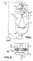
- Figure 1 is a schematic illustration of a preferred embodiment of the present invention; and
- Figure 2 is a schematic illustration of a modification.
- The description which follows refers specifically to the dispersion of a gas such as propylene or butene in a liquid such as sulfuric acid. However, it should be readily appreciated that the principles and concepts described herein are equally applicable to other processes in which contacting of distinct phases is desired.
- Turning now to Figure 1, there is shown a generally cylindrical, vertically disposed
vessel 10 having sidewalls 11 and top andbottom walls conduit 4 for removal of liquids for recycle via lines 5 and 6. A conduit 2 is provided for introduction of liquids recycled via lines 5 and 6. Vessel 10 is also equipped with a conduit 3 for removal of liquid product for delivery, for example, to a liquid product store (not shown).Line 8 is provided connecting a gaseous olefin source (not shown) with recycle line 6. Thus, a gaseous olefin and sulfuric acid may be fed together via conduit 2 into thevessel 10. - Conduit 2 contains disk and donut baffles, 18 and 19, respectively, for turning and mixing the gaseous olefin and liquid sulfuric acid as it passes through conduit 2. The mixture of gas and liquid then passes into a
pipe 21 centrally positioned in acylindrical mixing vessel 22. As can be seen,pipe 21 has a plurality ofholes 23 for further mixing of the gas and liquid. The fluid then exits themixing vessel 22 and flows into anozzle 24 which opens below the level of liquid 20 in thevessel 10. - The
nozzle 24 is designed to direct the flow of dispersed gas and liquid phases downwardly substantially in the central region of the vessel. Thus, the flow of dispersed phases ejected from the nozzle will flow outwardly as well as downwardly as shown by the dotted lines. The angle at which the dispersed phases are ejected fromnozzle 24 will depend upon a number of factors such as the ratio of the length to diameter of the vessel. In general, however, the angle of ejection of dispersed fluid phases fromnozzle 24 will be such that the fluid at its maximum length of downward travel will flow outwardly for a distance between .4 to .7 times the diameter ofvessel 10. The diameter of the nozzle is sufficient to transfer enough momentum from fluid ejected from the nozzle to fluid in its flow path to move from about 3 to about 20 times the amount of fluid ejected. This can be achieved by sizing the nozzle diameter to be from about 1/12 to about 1/20 the length of the vessel. - Located within
vessel 10 is abaffle 17 for directing the flow of dispersed fluid radially outwardly. This baffle is positioned substantially normal to the downward flow of fluid ejected fromnozzle 24 and placed near the bottom of the vessel. Indeed, it is preferred that the baffle has a diameter of from about 0.4 to about 0.7 times the diameter of the vessel and that it be located at a distance from the vessel bottom that is about 0.2 to about 0.5 times the diameter of the vessel. However, it should be noted that, unlike in the disclosure of published U.K. patent application 2222098A, thevessel 10 is devoid of any upright cylindrical circulation tube disposed inside thevessel 10 between thebaffle 17 and the surface of the liquid inside the vessel. - In operation then a mixture of the olefin and sulfuric acid is churned and mixed by the baffles in the conduit 2 and fed through
holes 23 ofpipe 21 causing extremely small bubbles to be formed. The gas and liquid mixture then is emitted as a jet of fluid fromnozzle 24 and is injected into the fluid contained in the vessel. The jet of fluid exiting the nozzle exchanges its momentum with the fluid in thecentral region 15 of the vessel especially the fluid directly in its conical flow path, and causes the fluid in this region to move in substantially a downwardly direction but also in an outwardly direction. This movement in turn causes the entire contents of the vessel to move. This fluid moves upwardly in theannular region 16 between the side walls 11 and thecentral region 15. As shown,baffle 17 deflects the jet energy of the fluids flowing downwardly, and deflects them radially outwardly preventing the energy from leaving through therecycle exit conduit 4. - In operation, recycle flows are adjusted to give five turnovers of fluid within the vessel or an axial liquid velocity within the vessel which is at least three times, for example, from three to five times, the buoyant rise velocity of the largest bubble in the vessel. This results in an extremely high vapor holdup of small bubbles formed by the
holes 23 ofpipe 21 and thenozzle 24. Furthermore, by maintaining a high recirculation rate within the vessel, bubble coalescence can be reduced with the concomitant result that the high interfacial areas that are generated by theholes 23 inmixer 22 are maintained. - Turning now to Figure 2, an alternate but particularly preferred embodiment of the present invention is shown. In this embodiment,
ring sparger pipes annular region 16 ofvessel 10. Preferably the spargers are located in theannular region 16 sufficiently abovebaffle 17 so as not to interfere with the downward flow of fluid fromcentral region 15. In operation, a portion of the gaseous olefin is sparged through theannular ring sparger 26 fromline 28 to aid in setting up and maintaining the flow of fluids circulating invessel 10. Similarly, a portion of the liquid acid is sparged throughring spargers 27 fromline 29. Indeed, it is particularly preferred that the openings in the gas sparger be substantially orthogonal to the openings in the liquid sparger as is described in greater detail in published U.K. patent application 2221166A. - When the ring sparger is used, from about five to about fifty percent of the total amount of gas fed to the vessel, and preferably about ten percent of the gas fed to the vessel is fed in the
annular region 16 through theannular sparger 26 providing a buoyancy driving force in the outerannular region 16 that stabilizes the recirculating flow. Typically the volumetric ratio of gas to liquid is in the range of from about 4:1 to about 1:2. - While in the preceding discussion specific mention was made with respect to using a gas and a liquid, in other applications, such as processes involving two distinct liquid phases or two liquid and one gaseous phase, it is preferred to circulate the recycle fluid through a separator drum, particularly where a phase volume ratio enhancement or control is desired over and beyond that available by proportioning the two liquid feeds to the reactor. This technique is described in published U.K. patent application 2222098A.
Claims (3)
- A method for improving the contacting of plural, distinct fluid phases, comprising at least a first liquid phase and a second liquid or gaseous phase, contained in a vertically disposed vessel, said vessel being devoid of any upright cylindrical circulation tube disposed inside the vessel below the level of the fluid therein, said method comprising: injecting a stream of dispersed distinct fluid phases together into the fluid contained in the vessel at a location below the fluid level to provide bubbles or droplets of said second phase in the fluid, said stream being injected at a velocity which is at least three times the buoyant rise velocity of the largest bubble or droplet in the vessel and with an angle of ejection such that at its maximum length of downward travel the injected fluid phases flow outwardly for a distance between .4 to .7 times the transverse dimension of the vessel, whereby the fluid in the vessel and the injected fluid are forced to flow downwardly through the central region of the vessel and upwardly in an annular region surrounding the central region, so that the dispersed phases are circulated and contacted.
- A method as claimed in claim 1, wherein a portion of said distinct phases is injected upwardly in the annular region surrounding the central region.
- A method as claimed in claim 1 or claim 2, wherein said first liquid phase is sulfuric acid and said second phase is an olefin.
Priority Applications (6)
| Application Number | Priority Date | Filing Date | Title |
|---|---|---|---|
| AT90304114T ATE106275T1 (en) | 1988-08-24 | 1990-04-17 | IMPROVED CONTACT BETWEEN SEVERAL DIFFERENT FLUID PHASES IN A VERTICALLY ARRANGED REACTOR. |
| DE69009457T DE69009457T2 (en) | 1988-08-24 | 1990-04-17 | Improved contact between several different fluid phases in a vertical reactor. |
| EP90304114A EP0452574B1 (en) | 1988-08-24 | 1990-04-17 | Improved contacting between plural distinct fluid phases contained in a vertically disposed vessel |
| CN90102606A CN1056263A (en) | 1988-08-24 | 1990-05-05 | The heterophase reactor of big boundary area |
| US07/665,637 US5190733A (en) | 1988-08-24 | 1991-02-14 | High interfacial area multiphase reactor |
| US07/966,634 US5340549A (en) | 1988-08-24 | 1992-10-26 | High interfacial area multiphase reactor (RM-1069) |
Applications Claiming Priority (5)
| Application Number | Priority Date | Filing Date | Title |
|---|---|---|---|
| US23557288A | 1988-08-24 | 1988-08-24 | |
| US31018289A | 1989-02-15 | 1989-02-15 | |
| EP90304114A EP0452574B1 (en) | 1988-08-24 | 1990-04-17 | Improved contacting between plural distinct fluid phases contained in a vertically disposed vessel |
| CN90102606A CN1056263A (en) | 1988-08-24 | 1990-05-05 | The heterophase reactor of big boundary area |
| US07/665,637 US5190733A (en) | 1988-08-24 | 1991-02-14 | High interfacial area multiphase reactor |
Publications (2)
| Publication Number | Publication Date |
|---|---|
| EP0452574A1 EP0452574A1 (en) | 1991-10-23 |
| EP0452574B1 true EP0452574B1 (en) | 1994-06-01 |
Family
ID=40120210
Family Applications (1)
| Application Number | Title | Priority Date | Filing Date |
|---|---|---|---|
| EP90304114A Expired - Lifetime EP0452574B1 (en) | 1988-08-24 | 1990-04-17 | Improved contacting between plural distinct fluid phases contained in a vertically disposed vessel |
Country Status (5)
| Country | Link |
|---|---|
| US (2) | US5190733A (en) |
| EP (1) | EP0452574B1 (en) |
| CN (1) | CN1056263A (en) |
| AT (1) | ATE106275T1 (en) |
| DE (1) | DE69009457T2 (en) |
Families Citing this family (5)
| Publication number | Priority date | Publication date | Assignee | Title |
|---|---|---|---|---|
| ES2048099B1 (en) * | 1992-04-22 | 1994-10-01 | Quimicos Del Mediterraneo S A | REACTOR FOR BECKMAN TRANSPOSITION OF CYCLLOHEXANONE OXIMA AND CYCLODODAN CANON OXIMA. |
| US5638740A (en) * | 1995-02-24 | 1997-06-17 | Cai; Zhihua | Apparatus for brewing espresso and cappuccino |
| EP2136908B1 (en) | 2007-03-15 | 2011-12-07 | Dow Global Technologies LLC | Mixer for a continuous flow reactor |
| WO2009149536A1 (en) * | 2008-06-10 | 2009-12-17 | Ekologix Earth-Friendly Solutions Inc. | Apparatus and process for treatment of wastewater and biological nutrient removal in activated sludge systems |
| CN110368878A (en) * | 2019-05-30 | 2019-10-25 | 南京杰科丰环保技术装备研究院有限公司 | Gas-liquid phase reactor for preparing sulfite |
Family Cites Families (15)
| Publication number | Priority date | Publication date | Assignee | Title |
|---|---|---|---|---|
| NL272954A (en) * | ||||
| US1180372A (en) * | 1914-04-03 | 1916-04-25 | Albert Breydel | Apparatus for treating oils, liquefied greases and fats, or any other liquids with nascent ozone. |
| US2128311A (en) * | 1935-04-20 | 1938-08-30 | Du Pont | Method of carrying out chemical reactions |
| US2413102A (en) * | 1941-11-25 | 1946-12-24 | American Viscose Corp | Degasifier |
| US3271304A (en) * | 1964-06-26 | 1966-09-06 | Pacific Flush Tank Co | Venturi aerator and aerating process for waste treatment |
| DE1906051A1 (en) * | 1969-02-07 | 1970-08-27 | Basf Ag | Process for the production of alkynols or alkynediols |
| AT291134B (en) * | 1969-04-24 | 1971-07-12 | Vogelbusch Gmbh | Device for gassing liquids, in particular for aerating flowing water |
| US3785779A (en) * | 1971-08-02 | 1974-01-15 | Exxon Research Engineering Co | Gas liquid inlet distributor |
| DE2410570C2 (en) * | 1974-03-06 | 1982-04-29 | Basf Ag, 6700 Ludwigshafen | Device for sucking in and compressing gases and mixing them with liquid |
| GB1573314A (en) * | 1976-04-14 | 1980-08-20 | Boc Ltd | Method and apparatus for dissolving gas in a body of liquid |
| DE2645780C2 (en) * | 1976-10-09 | 1982-10-07 | Basf Ag, 6700 Ludwigshafen | Process for gassing a liquid in a circulation reactor and for preventing unreacted gas from separating out of the liquid |
| DE2736872B2 (en) * | 1977-08-16 | 1979-07-19 | Basf Ag, 6700 Ludwigshafen | Process for the preparation of hydroxylammonium salts |
| US4564480A (en) * | 1978-12-20 | 1986-01-14 | Eduard Kamelmacher | Aeration system and method |
| DE3445904C2 (en) * | 1984-12-15 | 1986-12-04 | Dynamit Nobel Ag, 5210 Troisdorf | Method and device for carrying out heterogeneous, mass transport-limited reactions |
| GB2222098B (en) * | 1988-08-24 | 1992-03-18 | Exxon Research Engineering Co | Improvements in and relating to contacting of plural distinct fluid phases |
-
1990
- 1990-04-17 EP EP90304114A patent/EP0452574B1/en not_active Expired - Lifetime
- 1990-04-17 AT AT90304114T patent/ATE106275T1/en active
- 1990-04-17 DE DE69009457T patent/DE69009457T2/en not_active Expired - Fee Related
- 1990-05-05 CN CN90102606A patent/CN1056263A/en active Pending
-
1991
- 1991-02-14 US US07/665,637 patent/US5190733A/en not_active Expired - Fee Related
-
1992
- 1992-10-26 US US07/966,634 patent/US5340549A/en not_active Expired - Fee Related
Also Published As
| Publication number | Publication date |
|---|---|
| DE69009457T2 (en) | 1994-10-06 |
| CN1056263A (en) | 1991-11-20 |
| EP0452574A1 (en) | 1991-10-23 |
| US5340549A (en) | 1994-08-23 |
| US5190733A (en) | 1993-03-02 |
| ATE106275T1 (en) | 1994-06-15 |
| DE69009457D1 (en) | 1994-07-07 |
Similar Documents
| Publication | Publication Date | Title |
|---|---|---|
| US5154898A (en) | High interfacial area multiphase reactor | |
| US3833719A (en) | Method and apparatus for mixing gas and liquid | |
| US4931225A (en) | Method and apparatus for dispersing a gas into a liquid | |
| US2751335A (en) | Method and apparatus for mixing and contacting fluids | |
| US4683122A (en) | Gas-liquid reactor and method for gas-liquid mixing | |
| KR920000042B1 (en) | Improved gas - liquid mixing | |
| EP0792683B1 (en) | Tube and shell reactor system | |
| CN1070830C (en) | High-effect heat transfer and mass transfer for gas phase heterogeneous reaction | |
| CN1124176A (en) | Advanced gas control in gas-liquid mixing system | |
| EP0712655B1 (en) | Gas-liquid contact gas dispersion pipe and apparatus using the same | |
| DE1967739U (en) | DEVICE FOR THE PREPARATION OF FINE MIXING OF GASEOUS AND LIQUID MATERIALS. | |
| EP0452574B1 (en) | Improved contacting between plural distinct fluid phases contained in a vertically disposed vessel | |
| GB2222098A (en) | Improvements in and relating to contacting of plural distinct fluid phases | |
| US3867103A (en) | Alkylation apparatus | |
| CN111359539B (en) | Gas-liquid reaction method and gas-liquid reaction device capable of entering reaction preparation state in advance | |
| US5762687A (en) | Process and device for dissolving a quantity of gas in a flowing liquid quantity | |
| US4381268A (en) | Device for gassing liquids or suspensions | |
| US4961882A (en) | Fine bubble generator and method | |
| CN108348882A (en) | The system for making gas and liquid contact | |
| EP0839120B1 (en) | Method and apparatus for contacting gas and liquid | |
| US10603643B2 (en) | Process and device for dispersing gas in a liquid | |
| EA020355B1 (en) | An open pressurised agitated reactor and a method for mixing gas and slurry with each other | |
| KR101690978B1 (en) | Jet loop fludized bed reactor | |
| JPS61145131A (en) | Method and apparatus for carrying out heterogeneous substance transportation control reaction | |
| GB2221166A (en) | Generation of fine bubbles |
Legal Events
| Date | Code | Title | Description |
|---|---|---|---|
| PUAI | Public reference made under article 153(3) epc to a published international application that has entered the european phase |
Free format text: ORIGINAL CODE: 0009012 |
|
| AK | Designated contracting states |
Kind code of ref document: A1 Designated state(s): AT BE CH DE ES FR GB IT LI LU NL SE |
|
| 17P | Request for examination filed |
Effective date: 19920408 |
|
| 17Q | First examination report despatched |
Effective date: 19920804 |
|
| GRAA | (expected) grant |
Free format text: ORIGINAL CODE: 0009210 |
|
| AK | Designated contracting states |
Kind code of ref document: B1 Designated state(s): AT BE CH DE ES FR GB IT LI LU NL SE |
|
| PG25 | Lapsed in a contracting state [announced via postgrant information from national office to epo] |
Ref country code: LI Effective date: 19940601 Ref country code: ES Free format text: THE PATENT HAS BEEN ANNULLED BY A DECISION OF A NATIONAL AUTHORITY Effective date: 19940601 Ref country code: CH Effective date: 19940601 Ref country code: AT Effective date: 19940601 |
|
| REF | Corresponds to: |
Ref document number: 106275 Country of ref document: AT Date of ref document: 19940615 Kind code of ref document: T |
|
| REF | Corresponds to: |
Ref document number: 69009457 Country of ref document: DE Date of ref document: 19940707 |
|
| ET | Fr: translation filed | ||
| ITF | It: translation for a ep patent filed | ||
| PG25 | Lapsed in a contracting state [announced via postgrant information from national office to epo] |
Ref country code: SE Effective date: 19940901 |
|
| REG | Reference to a national code |
Ref country code: CH Ref legal event code: PL |
|
| PGFP | Annual fee paid to national office [announced via postgrant information from national office to epo] |
Ref country code: GB Payment date: 19950216 Year of fee payment: 6 |
|
| PGFP | Annual fee paid to national office [announced via postgrant information from national office to epo] |
Ref country code: LU Payment date: 19950401 Year of fee payment: 6 |
|
| PLBE | No opposition filed within time limit |
Free format text: ORIGINAL CODE: 0009261 |
|
| STAA | Information on the status of an ep patent application or granted ep patent |
Free format text: STATUS: NO OPPOSITION FILED WITHIN TIME LIMIT |
|
| PGFP | Annual fee paid to national office [announced via postgrant information from national office to epo] |
Ref country code: FR Payment date: 19950406 Year of fee payment: 6 |
|
| PGFP | Annual fee paid to national office [announced via postgrant information from national office to epo] |
Ref country code: BE Payment date: 19950428 Year of fee payment: 6 |
|
| PGFP | Annual fee paid to national office [announced via postgrant information from national office to epo] |
Ref country code: NL Payment date: 19950430 Year of fee payment: 6 |
|
| 26N | No opposition filed | ||
| PGFP | Annual fee paid to national office [announced via postgrant information from national office to epo] |
Ref country code: DE Payment date: 19950616 Year of fee payment: 6 |
|
| PG25 | Lapsed in a contracting state [announced via postgrant information from national office to epo] |
Ref country code: LU Free format text: LAPSE BECAUSE OF NON-PAYMENT OF DUE FEES Effective date: 19960417 Ref country code: GB Effective date: 19960417 |
|
| PG25 | Lapsed in a contracting state [announced via postgrant information from national office to epo] |
Ref country code: BE Effective date: 19960430 |
|
| BERE | Be: lapsed |
Owner name: EXXON RESEARCH AND ENGINEERING CY Effective date: 19960430 |
|
| PG25 | Lapsed in a contracting state [announced via postgrant information from national office to epo] |
Ref country code: NL Effective date: 19961101 |
|
| GBPC | Gb: european patent ceased through non-payment of renewal fee |
Effective date: 19960417 |
|
| PG25 | Lapsed in a contracting state [announced via postgrant information from national office to epo] |
Ref country code: FR Effective date: 19961227 |
|
| PG25 | Lapsed in a contracting state [announced via postgrant information from national office to epo] |
Ref country code: DE Effective date: 19970101 |
|
| NLV4 | Nl: lapsed or anulled due to non-payment of the annual fee |
Effective date: 19961101 |
|
| REG | Reference to a national code |
Ref country code: FR Ref legal event code: ST |
|
| PG25 | Lapsed in a contracting state [announced via postgrant information from national office to epo] |
Ref country code: IT Free format text: LAPSE BECAUSE OF NON-PAYMENT OF DUE FEES;WARNING: LAPSES OF ITALIAN PATENTS WITH EFFECTIVE DATE BEFORE 2007 MAY HAVE OCCURRED AT ANY TIME BEFORE 2007. THE CORRECT EFFECTIVE DATE MAY BE DIFFERENT FROM THE ONE RECORDED. Effective date: 20050417 |