EP0452291B1 - Verriegelungsvorrichtung für Briefordner - Google Patents
Verriegelungsvorrichtung für Briefordner Download PDFInfo
- Publication number
- EP0452291B1 EP0452291B1 EP91850084A EP91850084A EP0452291B1 EP 0452291 B1 EP0452291 B1 EP 0452291B1 EP 91850084 A EP91850084 A EP 91850084A EP 91850084 A EP91850084 A EP 91850084A EP 0452291 B1 EP0452291 B1 EP 0452291B1
- Authority
- EP
- European Patent Office
- Prior art keywords
- binder
- locking
- binders
- forks
- rings
- Prior art date
- Legal status (The legal status is an assumption and is not a legal conclusion. Google has not performed a legal analysis and makes no representation as to the accuracy of the status listed.)
- Expired - Lifetime
Links
Images


Classifications
-
- B—PERFORMING OPERATIONS; TRANSPORTING
- B42—BOOKBINDING; ALBUMS; FILES; SPECIAL PRINTED MATTER
- B42F—SHEETS TEMPORARILY ATTACHED TOGETHER; FILING APPLIANCES; FILE CARDS; INDEXING
- B42F13/00—Filing appliances with means for engaging perforations or slots
Definitions
- the present invention relates to an apparatus for making it possible to lock paper or document binders, in particular ring binders or fork binders, so that unauthorized persons can not reach the contents of the binders.
- binder is meant, in this connection, any binder for papers or documents etc., which binder has a ring means or a fork means for holding the papers or documents etc. in the binder, in that the papers, to this end, are punched and are mounted with the punch holes on the rings or forks when the binder is in open condition, whereupon the binder is closed thereby keeping the papers etc. therein.
- Binders containing secret material including quitations, price lists, contracts and other secret documents or papers, have so far normally been locked into cabinets, but generally only to a restricted extent, both for space reasons, and since it is considered a risk to put any and all secret documents in one place, and since there is always a risk that the attendent personel forgets locking said cabinet.
- the binders can be locked so that the contents thereof is available only for authorized persons.
- the Us patent 1,707,225 discloses an apparatus for locking a book and comprising an angularly bent anchoring strap which is in some way introduced in the book and is placed with the angle part thereof on the back side of the book between the actual back of the book and the rear edges of the leaves of the book, and which extends as far as to the front edges of the book covers and is locked in this position by means of one or two locking clamps which straddle over the front and back cover of the book, and whereby said anchoring strap projects through a slot of the locking clamp or clamps and is secured at the exterior thereof by means of a padlock.
- the said known apparatus is disadvantageous in that it is only useful for books in which it is possible to introduce the angularly bent anchoring strap into a position between the back edges of the book leaves and the back of the book; in that said apparatus is only useful for books having stiff front and back covers; in that it does not guarantee that the entire apparatus insluding the anchoring strap is not by violence pulled out in the direction of the front of the book whereby the angle portion of the anchoring strap becomes straightened temporarily depending on its own spring action or is permanently bent to straight shape; or in that the locking means may be released in that the back of the book is cut or torn open; in that it is not suited for ring binders or fork binders; and in that it comprises, in addition to the padlock, at least two separate anchoring parts.
- the object of the invention is to provide a binder locking apparatus which overcomes the above mentioned disadvantages in the known apparatus and which is especially suited for ring binders or fork binders of any type and size, which is formed as an integral object, and which is formed so that it is impossible to unpermittedly or by violence release said locking apparatus from the binder in the direction forwardly or rearwardly, or by cutting or tearing the back of the binder open.
- the apparatus according to the invention is formed so that the binders can stored in locked condition in ordinary shelf systems, both individually and in groups of binders, in that said binders can be locked individually by means of padlocks, or several binders together by means of a common locking means.
- the locking apparatus comprises a generally rectangular locking bracket having a shape and size substantially matching the horizontal width and depth of a binder, and which bracket is formed with a front part, two sides rails and back part which is split into two pieces, each piece having a through bore for the connection of a padlock, and further comprising an intermediate locking bar which is integral with the front part and extends rearwarly substantially parallelly to the side rails, and which is of such length as to place the end thereof at least partly behind the binder rings or forks.
- the locking apparatus can not be slided up or down in relation to the binder from a central position thereof, since said intermediate locking bar thereby lockingly engages one of the rings or forks of the apparatus.
- figure 1 is a perspective view of a first embodiment of the apparatus according to the invention.
- Figure 2 is a top view of the apparatus of figure 1 lockingly connected to an ordinary binder, and figure 3 is vertical cross section view, seen along lines III-III of figure 3.
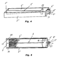
- Figure 4 is a perspective view of a second embodiment of an apparatus according to the invention, and figure 5 is a top view of the apparatus of figure 4 connected to a binder.
- the locking apparatus shown in figures 1-3 comprises a substantially rectangular bracket 1 having a shape and a size suited for snugly enclosing an ordinary binder in the horizontal direction.
- the bracket 1 is integral with a locking bar 2 extending inside the bracket 1, preferably parallelly therewith and adapted to engage the rings or the forks of a binder as shown in figures 2 and 3.
- the bracket 1 is substantially rectangular och comprises a front side 3, two parallel side rails 4, 5 and a split rear side 6, 7 having angularly outwardly/rearwardly directed flanges 8, 9 each having a through bore 10 and 11 respectively.
- the front side 3 is formed in three pieces, namely a central side portion 12 and on each side thereof a front flap 13 and 14 respectively.
- the flaps 13 and 14 are hinge connected to the central front side portion 12, and they are integral with the side rails 4 and 5.
- the front side 3 may be formed as a single piece, only that both the front side 3 and the side rails 4 and 5 are at least slightly resilient, so that the bracket 1 can be opened as shown in figure 1 to embrace a binder.
- the central front side piece 12 carries the locking bar 2, which in this case is formed as an elongated pin 15 having a hook 16 at the free end thereof.
- the locking pin 15 is of a length substantially matching the distance between the front edges of the binder covers and the rings or forks, and the hook 16 is, in the connection condition of the locking apparatus adapted to be located at least slightly behind the rings or forks, so that the pin hook 16 can be hooked on such a ring or fork, while having the front side pieces 13 and 14 of the apparatus engage the front ends of the binder covers, and having the rear side pieces 6 and 7 of the apparatus engage the back side of the cover.
- the bracket 1 and the locking bar 2 can be made of steel or any other metal or of a suitable plastic material.
- FIGS 2 and 3 there is illustrated how a binder 17 is locked by means of the above described apparatus, and it is shown that the apparatus is locked in that the apparatus is positioned round the binder and is closed over the binder 17; that the locking pin 2 is hooked onto a fork 18 of the binder; that the front side 3 is in contact with the front edges of the binder covers 19 and 20; and that the flanges 8 and 9 are in contact with the back 21 of the binder and engage, or at least come close to, each other; and that a padlock (not shown) or a similar lock is being introduced in the bores 10 and 11.
- FIGS 4 and 5 illustrate an alternative embodiment of the locking apparatus according to the invention.
- This second embodiment is made as an integral piece of material of a suitable plastic material.
- the locking bar 2′ which is integral with the front sid 3′, is formed substantially T-shaped in the vertical direction with the T-arms 22 at the outer end of the bar.
- the T-arms 22 are not arranged to be hooked onto a binder ring or a binder fork 18′, but they are only introduced into the area between two adjacent rings or forks.
- the locking apparatus can not be released in the front or back direction of the binder, but it can be slided a limited distance up and down on the binder, namely until a locking pin T-arm 22 engages one of the binder rings or forks 18′ in a hooking function, thereby stopping any further sliding up or down of the locking apparatus.
Landscapes
- Sheet Holders (AREA)
- Lock And Its Accessories (AREA)
- Plural Heterocyclic Compounds (AREA)
Claims (6)
- Vorrichtung zur Verriegelung von Blattheftern (17), insbesondere Ringbindern oder Gabelbindern zur Verhinderung des Zugriffs auf den Inhalt der Hefter durch nicht berechtigte Personen, gekennzeichnet durch:- eine im wesentlichen rechteckige Verriegelungsklammer (1) mit einer Vorderseite (3), einem Rückseitenteil (6 - 9) und Seitenstreben (4,5), die so bemessen ist, daß sie den Hefter in horizontaler Richtung umschließen und eine Länge und Breite aufweisen, die im wesentlichen an die entsprechenden Abmessungen des Hefters (17) angepaßt ist, so daß die Verriegelungsvorrichtung in ihrer geschlossenen Stellung sowohl sowohl mit den Vorderkanten der Einbanddecken (19) des Hefters, dem Hefterrücken (20), als auch mit mindestens einem Teil der seitlichen Einbanddecken (19,20) des Hefters (17) eingreift, wobei die Klammer an ihrem Rückseitenteil (6 - 9) entsprechend dem Rücken (21) des Hefters aufgespaltet und mit Flanschen (8,9) mit Bohrungen (10,11) zum Einsetzen beliebiger Verriegelungsmittel versehen ist,- eine Verriegelungsstange (2), die fest mit der Vorderseite (3) verbunden ist und sich in Richtung auf das Rückseitenteil (6 - 9) im wesentlichen parallel zu den Seitenstreben (4,5) erstreckt, wobei- die Verriegelungsstange zumindest geringfügig länger ist als der Hefterabstand zwischen der vertikalen Vorderkante des Heftereinbandes (19,20) und den Ringen oder Gabeln (18) und eine Hakeneinrichtung (16;22) aufweist, die so angeordnet ist, daß sie zwischen zwei der Ringe oder Gabeln (18) des Hefters (17) einsetzbar ist und mit einem der Ringe oder Gabeln (18) eingreift, um ein Verschieben der Verriegelungsvorrichtung entlang es Hefters (17) nach oben oder unten zu verhindern.
- Vorrichtung nach Anspruch 1, dadurch gekennzeichnet, daß die Hakeneinrichtung der Verriegelungsstange (2) ein Haken (16) ist, der so geformt ist, daß er in einen der Ringe oder Gabeln (18) des Hefters einhaken kann, während der Hefter geschlossen wird und danach die Verriegelungsvorrichtung geschlossen und mittels eine Vorhängeschlosses oder eines ähnlichen Verriegelungsmittels verriegelt werden kann.
- Vorrichtung nach Anspruch 1 oder 2, dadurch gekennzeichnet, daß die Vorderseite (3) der Vorrichtung einen zentralen Vorderseitenabschnitt (12), in dem die Verriegelungsstange (2) festgelegt ist, sowie an jeder Seite davon einen vorderen Laschenabschnitt (13,14) aufweist, die gelenkig mit dem zentralen Vorderseitenabschnitt (12) verbunden und integral mit den benachbarten Seitenstreben (4,5) ausgebildet sind.
- Vorrichtung nach Anspruch 1, dadurch gekennzeichnet, daß die Verriegelungsstange (2′) in vertikaler Richtung im wesentlichen T-förmig ausgebildet ist und daß ihre T-Enden (22) eine Hakeneinrichtung bilden, die zwischen zwei benachbarte Ringe oder Gabeln des Hefters eingreifen und in verriegelnden Eingriff mit einem der Ringe oder Gabeln gelangen kann, wenn die Verriegelungsvorrichtung relativ zu dem Hefter nach oben oder unten verschoben wird.
- Vorrichtung nach Anspruch 4, dadurch gekennzeichnet, daß die die Klammer (1′) und die Verriegelungsstange (2′) aufweisende Vorrichtung als einzelnes integrales Stück aus einem Material, zum Beispiel einem geeigneten Kunststoffmaterial, gebildet ist, welches eine genügende Elastizität zur federnden Öffnung bei der Montage der Vorrichtung an einem Hefter (17) und bei der Entfernung desselben aufweist.
- Vorrichtung nach mindestens einem der vorhergehenden Ansprüche, dadurch gekennzeichnet, daß das rückseitige Ende der Klammer gespalten ist, so daß die Seitenstreben (4,5) bei der Montage der Vorrichtung an einem Hefter (17) und bei der Abnahme der Vorrichtung von einem Hefter aufgespreizt werden können und daß die gespaltenen Rückseitenteile (6,7) mit winkelförmig gebogenen Flanschen (8,9) mit Bohrungen (10,11) zum Einsetzen eines Vorhängeschlosses, einer Verriegelungsstange oder eines ähnlichen Verriegelungsmittels ausgebildet sind.
Applications Claiming Priority (2)
| Application Number | Priority Date | Filing Date | Title |
|---|---|---|---|
| SE9001300 | 1990-04-10 | ||
| SE9001300A SE9001300L (sv) | 1990-04-10 | 1990-04-10 | Paermlaas medelst laasbygel |
Publications (2)
| Publication Number | Publication Date |
|---|---|
| EP0452291A1 EP0452291A1 (de) | 1991-10-16 |
| EP0452291B1 true EP0452291B1 (de) | 1994-06-22 |
Family
ID=20379142
Family Applications (1)
| Application Number | Title | Priority Date | Filing Date |
|---|---|---|---|
| EP91850084A Expired - Lifetime EP0452291B1 (de) | 1990-04-10 | 1991-04-03 | Verriegelungsvorrichtung für Briefordner |
Country Status (5)
| Country | Link |
|---|---|
| EP (1) | EP0452291B1 (de) |
| AT (1) | ATE107580T1 (de) |
| DE (1) | DE69102576T2 (de) |
| DK (1) | DK0452291T3 (de) |
| SE (1) | SE9001300L (de) |
Families Citing this family (1)
| Publication number | Priority date | Publication date | Assignee | Title |
|---|---|---|---|---|
| GB9826419D0 (en) * | 1998-12-03 | 1999-01-27 | Davies Alison J H | File with lock |
Family Cites Families (2)
| Publication number | Priority date | Publication date | Assignee | Title |
|---|---|---|---|---|
| US1707225A (en) * | 1927-10-21 | 1929-04-02 | Marshall H Jackson | Book lock |
| US1923081A (en) * | 1932-06-28 | 1933-08-22 | New York Merchandise Co Inc | Closure for books and similar articles |
-
1990
- 1990-04-10 SE SE9001300A patent/SE9001300L/ not_active Application Discontinuation
-
1991
- 1991-04-03 DE DE69102576T patent/DE69102576T2/de not_active Expired - Fee Related
- 1991-04-03 DK DK91850084.4T patent/DK0452291T3/da active
- 1991-04-03 EP EP91850084A patent/EP0452291B1/de not_active Expired - Lifetime
- 1991-04-03 AT AT91850084T patent/ATE107580T1/de active
Also Published As
| Publication number | Publication date |
|---|---|
| ATE107580T1 (de) | 1994-07-15 |
| SE9001300D0 (sv) | 1990-04-10 |
| DK0452291T3 (da) | 1994-07-25 |
| DE69102576D1 (de) | 1994-07-28 |
| SE9001300L (sv) | 1991-10-11 |
| DE69102576T2 (de) | 1994-10-13 |
| EP0452291A1 (de) | 1991-10-16 |
Similar Documents
| Publication | Publication Date | Title |
|---|---|---|
| US5337503A (en) | Manually lockable seal | |
| US5802888A (en) | Flexible strap restraining device | |
| US4886390A (en) | Loose leaf binder | |
| US5027622A (en) | Locking device for rods extending from merchandizing displays | |
| US4972689A (en) | Locking system | |
| EP0581811B1 (de) | Sicherheitsvorrichtung | |
| US5154527A (en) | Bracket for supporting binders in a hanging file | |
| CA1077367A (en) | Reference manual stand | |
| EP1278442B1 (de) | Haltesystem für schlüsselhalter | |
| EP0452291B1 (de) | Verriegelungsvorrichtung für Briefordner | |
| WO1998040591A1 (en) | An assembly, a method and a security device for securing and/or packaging a product temporarily | |
| US4494690A (en) | Container | |
| GB2337960A (en) | Ring binder with plurality of discrete housings for filing rings | |
| EP1311170B1 (de) | Sicherheitsvorrichtung | |
| US2220310A (en) | Container for automobile license certificates | |
| GB2287059A (en) | Security locking apparatus | |
| US4125299A (en) | File divider and indexing apparatus | |
| JP4939913B2 (ja) | 配達物不正取出防止具の取り付け方法 | |
| EP1171314B9 (de) | Verriegelbarer ordner | |
| AU661630B1 (en) | Shackle protector for padlocks | |
| AU2001278312B2 (en) | Security device | |
| NL8102382A (nl) | Cassette. | |
| US777708A (en) | Lock-seal. | |
| EP0995694A1 (de) | Ausstellungsträger für eine Spielzeugwaffe, besonders für eine Pistole | |
| DK174640B1 (da) | Løsbladsholdersystem |
Legal Events
| Date | Code | Title | Description |
|---|---|---|---|
| PUAI | Public reference made under article 153(3) epc to a published international application that has entered the european phase |
Free format text: ORIGINAL CODE: 0009012 |
|
| AK | Designated contracting states |
Kind code of ref document: A1 Designated state(s): AT CH DE DK FR GB LI NL SE |
|
| 17P | Request for examination filed |
Effective date: 19910902 |
|
| 17Q | First examination report despatched |
Effective date: 19930615 |
|
| RAP1 | Party data changed (applicant data changed or rights of an application transferred) |
Owner name: MEIER, HARALD |
|
| GRAA | (expected) grant |
Free format text: ORIGINAL CODE: 0009210 |
|
| AK | Designated contracting states |
Kind code of ref document: B1 Designated state(s): AT CH DE DK FR GB LI NL SE |
|
| REF | Corresponds to: |
Ref document number: 107580 Country of ref document: AT Date of ref document: 19940715 Kind code of ref document: T |
|
| REG | Reference to a national code |
Ref country code: DK Ref legal event code: T3 |
|
| REF | Corresponds to: |
Ref document number: 69102576 Country of ref document: DE Date of ref document: 19940728 |
|
| ET | Fr: translation filed | ||
| EAL | Se: european patent in force in sweden |
Ref document number: 91850084.4 |
|
| PG25 | Lapsed in a contracting state [announced via postgrant information from national office to epo] |
Ref country code: GB Effective date: 19950403 Ref country code: DK Effective date: 19950403 Ref country code: AT Effective date: 19950403 |
|
| REG | Reference to a national code |
Ref country code: DK Ref legal event code: EBP |
|
| PG25 | Lapsed in a contracting state [announced via postgrant information from national office to epo] |
Ref country code: SE Effective date: 19950404 |
|
| PLBE | No opposition filed within time limit |
Free format text: ORIGINAL CODE: 0009261 |
|
| STAA | Information on the status of an ep patent application or granted ep patent |
Free format text: STATUS: NO OPPOSITION FILED WITHIN TIME LIMIT |
|
| PG25 | Lapsed in a contracting state [announced via postgrant information from national office to epo] |
Ref country code: LI Effective date: 19950430 Ref country code: CH Effective date: 19950430 |
|
| 26N | No opposition filed | ||
| PG25 | Lapsed in a contracting state [announced via postgrant information from national office to epo] |
Ref country code: NL Effective date: 19951101 |
|
| GBPC | Gb: european patent ceased through non-payment of renewal fee |
Effective date: 19950403 |
|
| REG | Reference to a national code |
Ref country code: CH Ref legal event code: PL |
|
| PG25 | Lapsed in a contracting state [announced via postgrant information from national office to epo] |
Ref country code: FR Effective date: 19951229 |
|
| NLV4 | Nl: lapsed or anulled due to non-payment of the annual fee |
Effective date: 19951101 |
|
| PG25 | Lapsed in a contracting state [announced via postgrant information from national office to epo] |
Ref country code: DE Effective date: 19960103 |
|
| EUG | Se: european patent has lapsed |
Ref document number: 91850084.4 |
|
| REG | Reference to a national code |
Ref country code: FR Ref legal event code: ST |