EP0452239B1 - Nehrfachsfunktionssteuerungssystem mit elektroakustischen Mitteln zur Auswahl von durch einen Benutzer aktivierbaren Funktionen und Mittel zur Gültigkeitserklärung dieser Auswahl - Google Patents
Nehrfachsfunktionssteuerungssystem mit elektroakustischen Mitteln zur Auswahl von durch einen Benutzer aktivierbaren Funktionen und Mittel zur Gültigkeitserklärung dieser Auswahl Download PDFInfo
- Publication number
- EP0452239B1 EP0452239B1 EP19910460021 EP91460021A EP0452239B1 EP 0452239 B1 EP0452239 B1 EP 0452239B1 EP 19910460021 EP19910460021 EP 19910460021 EP 91460021 A EP91460021 A EP 91460021A EP 0452239 B1 EP0452239 B1 EP 0452239B1
- Authority
- EP
- European Patent Office
- Prior art keywords
- counting
- selection
- signal
- pulses
- predetermined
- Prior art date
- Legal status (The legal status is an assumption and is not a legal conclusion. Google has not performed a legal analysis and makes no representation as to the accuracy of the status listed.)
- Expired - Lifetime
Links
- 230000006870 function Effects 0.000 title claims description 41
- 238000012545 processing Methods 0.000 claims description 12
- 230000004913 activation Effects 0.000 claims description 8
- 238000001514 detection method Methods 0.000 claims description 8
- 238000012546 transfer Methods 0.000 claims description 5
- 125000004122 cyclic group Chemical group 0.000 claims description 2
- 230000000007 visual effect Effects 0.000 claims description 2
- 230000029058 respiratory gaseous exchange Effects 0.000 claims 2
- 230000030808 detection of mechanical stimulus involved in sensory perception of sound Effects 0.000 claims 1
- 238000010200 validation analysis Methods 0.000 description 10
- 230000000630 rising effect Effects 0.000 description 5
- 238000000034 method Methods 0.000 description 4
- 230000001960 triggered effect Effects 0.000 description 3
- 230000003213 activating effect Effects 0.000 description 2
- 238000007664 blowing Methods 0.000 description 2
- 230000033764 rhythmic process Effects 0.000 description 2
- 230000035945 sensitivity Effects 0.000 description 2
- 240000008042 Zea mays Species 0.000 description 1
- 238000013459 approach Methods 0.000 description 1
- 238000006243 chemical reaction Methods 0.000 description 1
- 238000012937 correction Methods 0.000 description 1
- 230000000694 effects Effects 0.000 description 1
- 238000001914 filtration Methods 0.000 description 1
- 238000012423 maintenance Methods 0.000 description 1
- 230000006386 memory function Effects 0.000 description 1
- 230000003387 muscular Effects 0.000 description 1
- 238000011084 recovery Methods 0.000 description 1
- 238000007493 shaping process Methods 0.000 description 1
- 238000001228 spectrum Methods 0.000 description 1
Images


Classifications
-
- A—HUMAN NECESSITIES
- A61—MEDICAL OR VETERINARY SCIENCE; HYGIENE
- A61F—FILTERS IMPLANTABLE INTO BLOOD VESSELS; PROSTHESES; DEVICES PROVIDING PATENCY TO, OR PREVENTING COLLAPSING OF, TUBULAR STRUCTURES OF THE BODY, e.g. STENTS; ORTHOPAEDIC, NURSING OR CONTRACEPTIVE DEVICES; FOMENTATION; TREATMENT OR PROTECTION OF EYES OR EARS; BANDAGES, DRESSINGS OR ABSORBENT PADS; FIRST-AID KITS
- A61F4/00—Methods or devices enabling patients or disabled persons to operate an apparatus or a device not forming part of the body
-
- H—ELECTRICITY
- H04—ELECTRIC COMMUNICATION TECHNIQUE
- H04M—TELEPHONIC COMMUNICATION
- H04M1/00—Substation equipment, e.g. for use by subscribers
- H04M1/247—Telephone sets including user guidance or feature selection means facilitating their use
- H04M1/2474—Telephone terminals specially adapted for disabled people
-
- H—ELECTRICITY
- H04—ELECTRIC COMMUNICATION TECHNIQUE
- H04M—TELEPHONIC COMMUNICATION
- H04M1/00—Substation equipment, e.g. for use by subscribers
- H04M1/26—Devices for calling a subscriber
- H04M1/27—Devices whereby a plurality of signals may be stored simultaneously
Definitions
- the field of the invention is that of device control devices from activation means other than touch or manual contacts of the push button, switch, etc. type.
- the present invention relates to a device for controlling devices by sound, and in particular breath, which can in particular be used by disabled people.
- Manual control of devices is also unsuitable in certain situations encountered by perfectly able-bodied people, for example when it is necessary to carry out several tasks simultaneously in a professional environment, or more simply for reasons of comfort (remote control or without muscular effort).
- voice-activated devices have been developed.
- speech recognition to switch devices on or off, or to perform a particular function.
- these devices do not function satisfactorily in noisy environments.
- Two types of problem can indeed arise: the non-detection of commands covered by noise and the detection of false commands, by assimilating an untimely noise to an order.
- the present invention aims in particular to overcome these drawbacks.
- a first objective of the invention is to present a device for selecting multifunction control channels making it possible to easily select, by sound, and in particular breath, a function from a large number of selectable functions.
- Another objective of the invention is to allow such selection by sound, in particular breath, by means of a device and according to a process which allow great security of selection.
- a particular objective of the invention is to provide such a device which allows the generation of each digit of a telephone number successively, and the automatic dialing of a number previously stored in an electronic "diary" under a reference number, by simple "sound" selection of the reference number.
- this device allows the user to act on the preselection at his own pace: brief breath stops cause the incrementation to slow down.
- said incrementing of the counting means is cyclical, the preselection of the last of said channels according to said predetermined preselection order being followed by the preselection of the first of said channels.
- the senor is an electro-acoustic transducer sensitive essentially to breath, such as an electret microphone.
- the signal processing block from the sensor generates pulses each formed on each detection of a peak in the signal from the sensor of a value greater than a predetermined and / or adjustable threshold.
- the block for processing the electrical signal coming from the sensor comprises thresholding means making it possible to distinguish a control breath from other sounds.
- the signal processing block cooperates with means for resetting the pulse counting means when a predetermined number of pulses is not reached in the period of time. predetermined and / or adjustable.
- the counting means cooperate with precounting means, said precounting means being requested first at the start of each sound detection, and allowing the activation of said counting means only when a predetermined number of precounting pulses has been recorded for a predetermined time.
- the device comprises means for validating the selected channel, activated by the selection of a specific validation channel from among the preselected channels.
- the device of the invention allows the selection of telephone functions, of the type of functions for dialing a telephone call number.
- This device then comprises means for transcoding the value taken by the counting means into a signal representative of the corresponding telephone function, according to a preset transcoding table.
- the transcoding table associates with each value from the counting means a complex alphanumeric word, in particular a telephone number, the table controlling, for each selected function, a unit delivering to the counting means a set of pulses calibrated corresponding to this function.
- the device comprises means for displaying the operations carried out, in the form of a pair of visual displays for each selectable function, the first display of each pair indicating that the current function is preselected and the second display confirming the selection of the corresponding function.
- the embodiment of the invention presented below relates to a multifunction control device selectively sensitive to breath.
- a device thus has the advantages of being usable in a noisy environment, by any operator (in particular disabled) simply capable of exhaling air by the mouth for a controllable and variable duration.
- FIG. 1 represents the signal detected by an electret microphone in the presence of a breath (1), then in the presence of speech (2).
- An electret microphone therefore delivers signals of very high levels in the case of breath 1.
- the amplitude delivered is, however, much lower than that from a breath 1.
- breath 1 is relatively easy to distinguish breath 1 from speech 2, by simple thresholding 3. It is thus possible to operate in a noisy ambient environment, the device taking account only of breath 2.
- FIG. 2 represents a preferred embodiment of the device of the invention. This mode of implementation corresponds to the generation of a telephone number.
- the breath signal is picked up by an electret microphone 20 which transforms the perceived breath into an electrical signal, the appearance of which is shown in FIG. 1.
- This electrical signal is transmitted 21 to a signal processing block 22 comprising two modules 23, 24.
- the first module 23 performs filtering and shaping of the signal from the electret microphone 20.
- the second module 24 converts the filtered and shaped signal into a digital clock. This conversion is carried out by comparing the amplitude of the signal processed with a threshold value 3 to generate a clock pulse at each crossing of the threshold.
- This threshold 3 is represented in FIG. 1. If the amplitude of the input signal 21 is greater than the value of the threshold 3, a logic level "1" appears at the output of the module 24. This threshold 3 is adjusted to a value allowing not to take into account a speech signal 2 (fig. 1). It can also be adjustable by the user.
- the output signal 25 from the processing block 22 therefore corresponds to a logic clock whose frequency is a function of each overshoot of the level 3 of the breath signal picked up by the electret microphone 20, and / or of the duration of these overshoots.
- the latter is advantageously chosen to be high enough so that, even in the presence of a continuous breath, it is regularly crossed as illustrated in FIG. 1.
- This clock signal 25 is transmitted simultaneously to two blocks: a timer block 26 and a counting block 27.
- the timer block 26 controls in particular the reset of the counting block 27, when no breath has been recorded for a predetermined duration.
- FIG. 3A shows an example of a timing block consisting of a set of monostables 30, 31.
- the inverted output 32 When there are no more pulses at the input 25 of the first monostable 30, the inverted output 32 therefore goes to the high level.
- the rising edge causes the activation of the second monostable 31 for a period T1 of approximately 2.2 seconds.
- This time T1 is of course only a preferential value suitable for the use which is made of the device according to the invention, and another value of the same order of magnitude may also be suitable. This value can in particular be adjusted by the user.
- the output 201 of the second monostable 31 thus remains active the time of the presence of the breath increased by the time T1.
- the signal from the second monostable 31 is validated (it goes to 1) and causes a selection order on the link 201.
- a NAND gate 35 commands the reinitialization 29 of the block for counting the pulses via the reset means 28 (FIG. 2), with a delay making it possible to make a selection before the reset 29.
- This embodiment therefore consists in using the non-continuity of the signal 25 (clock), each new crossing of the threshold 3 causing an extension of the validation of the monostable 31 by a time T1.
- This timer block allows a very brief interruption of the breath to neither result in the complete reset of the counting nor an unwanted selection. It is thus possible to control the device of the invention by a continuous breath and / or by a series of breaths. This allows the user to "catch his breath”.
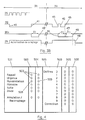
- FIG. 3B represents the state of the outputs of the monostables 30, 31, and the commands carried out 29, 201 in the case of a continuous breath 38 then in the case of a breath with repeats 39.
- the first monostable 30 is triggered 40 by the appearance of pulses generated by a breath.
- the second monostable 31 is triggered during a guard time T1 or its validation is extended by a duration T1.
- the output 201 of the second monostable 31 changes to "1".
- the rising edge 42 generated validates the preselection made (FIG. 2) and resets 29 the counting block 27 of pulses using the initialization means 28.
- each new breath interruption 43 generates the activation 44 of the second monostable 31. If during the period T1 new pulses are detected at the input of the first monostable 30, the selection orders 201 and 200 are not generated. These do not will be only in the case of a breath interruption of duration greater than the T1 guard time.
- the resumption of breath during this period T1 in fact generates new pulses at the input 25 of the timer block and retriggers 45 the first monostable 30.
- the second monostable 31 deactivates at the end of the time T1 and causes a selection order 48 on the link 201 then, using the initialization block 28, an initialization order 49.
- This implementation mode therefore makes it possible to interrupt the breath for a time less than or equal to T1 without making a selection.
- the clock signal 25 is of a frequency greater than a certain value so that an interruption of breath of approximately second is allowed (for a guard time T1 of 2.2 s), to allow an extension of a new T1 on-call time.
- the duration of keeping the low time by this monostable 30 is chosen so that brief low levels at the input 25 do not cause the output 32 to go into the state high.
- the user has, after the breath interruption, the entire guard time T1 to start blowing again in the sensor 20.
- This embodiment has the advantage of offering better reliability of the device according to the invention, in particular in the case of a high power blast (high signal time 25) and of duration close to the guard time. T1.
- timing block 26 makes it possible to take into account the breath signals 25 having a high time (of activation) of duration close to T1, without making a selection. It also offers the possibility of interrupting a breath for a time very close to T1, since we do not count on a certain frequency of the signal 32 for the triggering of the monostable 31. Thus, it is only the first rising edge of the signal 25 which is taken into account to extend the duration of maintenance of the monostable 31 performing the selection operation.
- the pulses 25 generated by the processing block 22 are transmitted, in addition to the timer block 26, to the pulse counting means 27.
- These means will consist of a precounting module 202 and a counting module 203.
- the precounting module 202 makes it possible to adjust the sensitivity of the system to the possible difficulties of blowing the user, to make the command more or less sensitive, to the detriment of the selectivity of the breath.
- the precounting module 202 also constitutes a counting precondition, making it possible to minimize the risks of untimely tripping caused by brief noises, for example door slaps.
- the precounting means 202 supply pulses to the counter 203 only after a certain number of pulses have been precounted in the time interval T1.
- the precounting module 202 thus constitutes a minimum counting threshold to be exceeded so that the pulses are taken into account by the counter 203.
- the pulse counting means 203 25 are moreover reset, as we have seen, when a predetermined number of pulses is not reached in the predetermined and / or adjustable period of time (T1).
- the counting block 27 is therefore initialized by the timing block 26 via reset means 28.
- the module 203 counts the number of pulses supplied to it by the precounting module 202. It has on its outputs 204 a binary word representative of the number of pulses counted. This binary word is decoded by a decoding module 205, which associates with this binary word the corresponding preselected function or digit.
- the decoding module 205 therefore continuously monitors the evolution of the counter.
- the decoding module 205 does the decoding only when the validation signal 201 is sent.
- the module 205 has at its output a certain number of channels 206 of which only one is activated (preselected) at a time.
- This channel is that of the current digit or function preselected using the breath sensor 20.
- the preselected channel is selected using the transfer block 207 which copies on its outputs 208 the levels present on its inputs 206, when it detects a transfer order 201 generated by the timer block 26.
- validation channel 209 Before being able to carry out the actual commands, it may be interesting to validate the selected channel. This validation is carried out by the selection of a particular channel, called validation channel 209. The selection of this channel and the processing of the information by a management module 210 then ensures validation 211 of the selection already transmitted to the block of command 212. This control block 212 then sends the corresponding commands to the device to be controlled on the command channels 213.
- control block 212 can advantageously be constituted by a microprocessor unit managing the selected channels 208. This makes it possible to select all the digits of the telephone number successively and thereafter to perform a single validation operation 211.
- microprocessor for managing the selected channels 208 also makes it possible to dispense with the management module 210 of the validation channel 209 and to validate a command directly by the channel 214.
- the generation of a telephone number by successive selection of the digits composing this number is carried out in the main progression zone.
- the other zones correspond to the selection of particular functions. The fact of managing different areas of progression makes it possible to simplify the dialogue with the user, and to limit the selection time (it is not necessary to scan all the channels likely to be selected).
- Block 215 makes it possible to select counting areas and validation words.
- This block 215 can be programmed either by software or by logic circuits. It allows you to loop through a number of functions allowing access to different areas depending on the applications of the device. Programming this block also allows you to loop through each selected zone.
- the data coming from this block 215 are transcoded by a module 216.
- the program makes it possible to generate a certain number of pulses on a line 217 connected to the counting block 203 previously reset, via the module 28 for initialization, from a command 218 coming from the transcoding module 216.
- the number of pulses generated appears at the output of the counting module on the lines 204 connected to the decoding block 205 and the process previously described is repeated in another progress zone .
- FIG. 4 is an example of a representation of a telephone dial adapted to the present invention.
- This dial 500 is divided into two parts, corresponding overall to the functions 501 and to the numbers 502. It has two ramps of two pairs of displays 503,504,505,506. These ramps constitute a user-device interface allowing the user to view the operations carried out.
- the ramps 503.505 and 504.506 consist for example of diodes light emitting 507 connected respectively to the preselection 206 and selection channels 208.
- the user wants to dial a digit-by-digit number, he actuates the sensor 20 (in this case the breath sensor), which has the effect of switching on and for a few fractions of seconds the light-emitting diodes 507 of the ramp 503.
- the sensor 20 in this case the breath sensor
- the light-emitting diode 509 located opposite that previously illuminated 508 in turn lights up in the ramp 504 at the end of the guard time T1 of the second monostable 31 of FIG. 3A.
- the NUMBERING function is then selected, without however being validated, which makes it possible to be able to select another function by re-requesting the sensor 20, if the choice of the previous selection was an error.
- the SEND function In order to validate the selected function, the SEND function must be selected in the same way as above. The procedure is continued by pressing the sensor 20 again to preselect a number on the ramp 505. At the end of the guard time T1, the preselected digit is selected and the light-emitting diode located opposite that indicating the preselected digit lights up. This procedure must be carried out as many times as there are digits in the telephone number to dial. Means for viewing the number being dialed are advantageously arranged near the ramps. Once the last digit of the number has been selected, the complete number is validated by the SEND function. This number is then generated by the microprocessor unit included in the control block.
- the device according to the invention may also include a display block 219 (FIG. 2) informing the user that his breath signal is well taken into account.
- the counting is cyclic scrolling, that is to say that an incrementation of the maximum value of the counter causes this counter to return to zero.
- the commented figure includes in particular the REMINDER functions making it possible to recall the last number generated, EMERGENCY making it possible to generate numbers specific to services of the police, fire brigade type, etc., by selecting a serial number in a list and CORRECTION for deleting a selected digit.
- the device according to the invention can be applied to the control of devices other than telephone sets.
- transducer used is not a critical choice, any transducer generating a signal all the time of its activation can be used. Depending on the type of sensor used, it may be necessary to modify the structure of the processing block 22, in order to adapt it to the types of electrical signals supplied by the sensor.
- the display means can also consist of mechanical indicators or systems using speech synthesizers.
- FIGS. 1, 2, 3A, 3B and 4 do of course only represent a specific embodiment of the invention. Those skilled in the art will easily imagine other applications falling within the scope of the present invention.
Landscapes
- Engineering & Computer Science (AREA)
- Signal Processing (AREA)
- Human Computer Interaction (AREA)
- Health & Medical Sciences (AREA)
- Biomedical Technology (AREA)
- Heart & Thoracic Surgery (AREA)
- Vascular Medicine (AREA)
- Life Sciences & Earth Sciences (AREA)
- Animal Behavior & Ethology (AREA)
- General Health & Medical Sciences (AREA)
- Public Health (AREA)
- Veterinary Medicine (AREA)
- Computer Vision & Pattern Recognition (AREA)
- Telephone Function (AREA)
- Respiratory Apparatuses And Protective Means (AREA)
Claims (10)
- Vorrichtung zur Auswahl von Steuerungskanälen, insbesondere zum Steuern von Geräten oder von Funktionen der Art, die über die Tastatur eines Telefons aktivierbar sind, wobei es sich um eine Vorrichtung handelt, die auf Schall und insbesondere auf Atemgeräusche reagiert, dadurch gekennzeichnet, daß sie folgendes umfaßt:- Mittel (212) zum Steuern von mindestens zwei verschiedenen Steuerkanälen (208);- Mittel (203) zum Zählen von Impulsen (25), wobei jeder Wert, den die Zählmittel (203) annehmen einem der Kanäle (208) entspricht, und wobei die Inkrementierung der Zählmittel (203) nach einer vorher festgelegten Auswahlordnung erfolgt;- Mittel (22) zur Bearbeitung eines elektrischen Signals (21), das aus einem Meßfühler (20) kommt und die Impulse (25) produziert, wenn das elektrische Signal (21) repräsentativ für einen vorgegebenen und/oder regelbaren minimalen Geräuschpegel ist;- Verzögerungsmittel (26), die das Erzeugen eines Auwahlsignals (201) ermöglichen, wenn die Zählmittel (203) nach einem vorher festgelegten und/oder regelbaren Zeitintervall (T1) nicht wieder inkrementiert wurden;- Mittel (207) für die Übertragung des in den Zählmitteln (203) enthaltenen Wertes (204) zu den Steuerungsmitteln (212), wobei die Übertragungsmittel (207) aktiv sind, wenn die Verzögerungsmittel (26) das Auswahlsignal (201) erzeugen.
- Vorrichtung gemäß Anspruch 1,
dadurch gekennzeichnet, daß die Inkrementierung der Zählmittel (203) zyklisch ist, wobei auf die Vorauswahl des letzten Kanals gemäß der Vorauswahlordnung, die Vorauswahl des ersten Kanals folgt. - Vorrichtung gemäß einem der Ansprüche 1 oder 2,
dadurch gekennzeichnet, daß es sich beim Meßfühler (20) um einen elektroakustischen Wandler handelt, der vornehmlich auf Atemgeräusche reagiert, wie beispielsweise ein Elektretmikrofon. - Vorrichtung gemäß einem der Ansprüche 1 bis 3,
dadurch gekennzeichnet, daß die Mittel (22) zur Bearbeitung des Signals (21), das aus dem Meßfühler (20) kommt, Impulse (25) erzeugen, die jeweils bei der Erfassung einer Spitze des aus dem Meßfühler (20) kommenden Signals gebildet werden, und deren Wert oberhalb eines im voraus festgelegten und/oder regelbaren Schwellwerts (3) liegt. - Vorrichtung gemäß einem der Ansprüche 1 bis 4,
dadurch gekennzeichnet, daß die Mittel (22) zur Signalbearbeitung mit den Mitteln (28) zur Reinitialisierung der Mittel (203) zum Zählen der Impulse (25) zusammenarbeiten, wenn eine im voraus festgelegte Zahl von Impulsen nicht innerhalb des vorgegebenen und/oder regelbaren Zeitintervalls (T1) erreicht wurde. - Vorrichtung gemäß einem der Ansprüche 1 bis 5,
dadurch gekennzeichnet, daß die Zählmittel (203) mit Mitteln (202) zum Vorauszählen zusammenarbeiten, wobei die Mittel (202) zum Vorauszählen als erstes beim Einsetzen einer jeden Schallerfassung aufgerufen werden und die Aktivierung der Zählmittel (203) nur dann zulassen, wenn eine im voraus gegebene Zahl von Impulsen zum Vorauszählen während einer vorgegebenen Zeit registriert wurde. - Vorrichtung gemäß einem der Ansprüche 1 bis 6,
dadurch gekennzeichnet, daß sie über Mittel (212) zum Validieren des ausgewählten Kanals (208) verfügt, welche durch die Auswahl (201) eines spezifischen Validierungskanals unter den Kanälen (206) aktiviert werden. - Vorrichtung gemäß einem der Ansprüche 1 bis 7,
dadurch gekennzeichnet, daß sie von der Art ist, welche die Auswahl von Telefonfunktionen ermöglicht, insbesondere das Wählen einer Telefonnummer und,
daß sie über Mittel (216) zum Umkodieren des von den Zählmitteln (203) angenommenen Wertes zu einem Signal verfügt, das repräsentativ für die entsprechende Telefonfunktion ist, gemäß einer im voraus festgelegten Umkodierungstabelle. - Vorrichtung gemäß Anspruch 8,
dadurch gekennzeichnet, daß die Umkodierungstabelle jedem Wert der Zählmittel (203) ein komplexes alphanumerisches Wort zuordnet, insbesondere eine Telefonnummer und,
daß die Tabelle für jede gewählte Funktion eine Einheit steuert, die den Zählmitteln (203) einen Satz kalibrierter Impulse (217) zur Verfügung stellt, welche dieser Funktion entsprechen. - Vorrichtung gemäß einem der Ansprüche 1 bis 9,
dadurch gekennzeichnet, daß sie über Mittel (503, 504, 505, 506) verfügt, um die ausgeführten Operationen sichtbar zu machen, in der Form eines Paars (508, 509) von Anzeigeeinheiten für jede ausgewählte Funktion, wobei die erste Anzeigeeinheit (508) eines jeden Paars die laufende vorgewählte Funktion angibt, und die zweite Anzeigeeinheit die Wahl der entsprechenden Funktion bestätigt.
Applications Claiming Priority (2)
| Application Number | Priority Date | Filing Date | Title |
|---|---|---|---|
| FR9004786 | 1990-04-10 | ||
| FR9004786A FR2660820A1 (fr) | 1990-04-10 | 1990-04-10 | Systeme de commande multifonctions comportant des moyens electroacoustiques de selection de fonctions activables par un operateur et des moyens de validation de la selection. |
Publications (2)
| Publication Number | Publication Date |
|---|---|
| EP0452239A1 EP0452239A1 (de) | 1991-10-16 |
| EP0452239B1 true EP0452239B1 (de) | 1995-07-26 |
Family
ID=9395759
Family Applications (1)
| Application Number | Title | Priority Date | Filing Date |
|---|---|---|---|
| EP19910460021 Expired - Lifetime EP0452239B1 (de) | 1990-04-10 | 1991-04-10 | Nehrfachsfunktionssteuerungssystem mit elektroakustischen Mitteln zur Auswahl von durch einen Benutzer aktivierbaren Funktionen und Mittel zur Gültigkeitserklärung dieser Auswahl |
Country Status (3)
| Country | Link |
|---|---|
| EP (1) | EP0452239B1 (de) |
| DE (1) | DE69111503T2 (de) |
| FR (1) | FR2660820A1 (de) |
Families Citing this family (1)
| Publication number | Priority date | Publication date | Assignee | Title |
|---|---|---|---|---|
| DE20211929U1 (de) * | 2002-08-02 | 2003-12-11 | Petra-Electric Peter Hohlfeldt Gmbh & Co | Atemgeräuschkontrollvorrichtung |
Family Cites Families (7)
| Publication number | Priority date | Publication date | Assignee | Title |
|---|---|---|---|---|
| US3725602A (en) * | 1970-12-28 | 1973-04-03 | Bell Telephone Labor Inc | Machine control by acoustic energy |
| US3836959A (en) * | 1973-02-05 | 1974-09-17 | Pantex Corp | Apparatus for activating remotely located devices in response to acoustical signals |
| GB2006495B (en) * | 1977-07-15 | 1982-10-20 | Mettoy Co Ltd | Remote control apparatus and to toys utilising such apparatus |
| US4275266A (en) * | 1979-03-26 | 1981-06-23 | Theodore Lasar | Device to control machines by voice |
| AU557720B2 (en) * | 1982-07-15 | 1987-01-08 | Thomas Michael Kenny | Remote control apparatus |
| US4562432A (en) * | 1982-08-19 | 1985-12-31 | Steve Sremac | Voice or blow-controlled switchboard |
| FR2640405B1 (fr) * | 1988-12-09 | 1994-09-16 | France Etat | Procede et dispositif d'elaboration d'un signal de commande sensible essentiellement au souffle |
-
1990
- 1990-04-10 FR FR9004786A patent/FR2660820A1/fr not_active Withdrawn
-
1991
- 1991-04-10 DE DE1991611503 patent/DE69111503T2/de not_active Expired - Fee Related
- 1991-04-10 EP EP19910460021 patent/EP0452239B1/de not_active Expired - Lifetime
Also Published As
| Publication number | Publication date |
|---|---|
| FR2660820A1 (fr) | 1991-10-11 |
| EP0452239A1 (de) | 1991-10-16 |
| DE69111503D1 (de) | 1995-08-31 |
| DE69111503T2 (de) | 1996-04-04 |
Similar Documents
| Publication | Publication Date | Title |
|---|---|---|
| FR2671893A1 (fr) | Systeme d'appel de personnes avec composition automatique de numeros et procede s'y rapportant. | |
| FR2803024A3 (fr) | Hotte aspirante pour cuisine | |
| FR2466151A1 (fr) | Systeme memorisateur et indicateur de numeros de telephone | |
| EP0451056B1 (de) | Telephonische elektronische Vorrichtung | |
| WO1994027844A1 (fr) | Appareil automatique de securite pour des vehicules avec un enregistrement inviolable des sons et des images | |
| FR2796234A1 (fr) | Systeme et procede de controle de l'interface utilisateur d'un appareil d'electronique grand public | |
| EP0452239B1 (de) | Nehrfachsfunktionssteuerungssystem mit elektroakustischen Mitteln zur Auswahl von durch einen Benutzer aktivierbaren Funktionen und Mittel zur Gültigkeitserklärung dieser Auswahl | |
| FR2668280A1 (fr) | Dispositif emetteur de sequences de signaux. | |
| EP0377379A1 (de) | Automatische Telefonrufvorrichtung | |
| EP0112429B1 (de) | System zur Übertragung von Daten durch sich wiederholende Folgen | |
| EP1995709A2 (de) | Hilfsvorrichtung für Personen mit Kommunikationsschwierigkeiten | |
| FR2757301A1 (fr) | Dispositif d'avertissement de la presence d'un signal | |
| EP0709998A2 (de) | Zweidraht-Kommunikationssystem für Gegensprechanlagen | |
| FR2725019A1 (fr) | Dispositif de mesure de distance. | |
| FR2571523A1 (fr) | Transmetteur automatique de signaux, tels qu'un message d'alarme, sur ligne telephonique | |
| EP0100523A1 (de) | Verfahren zur Informationsübertragung über einen einzigen Übertragungskanal und Anwendung dieses Verfahrens insbesondere in Einrichtungen die ein Alarmsystem bilden | |
| EP0200635B1 (de) | Codierungseinrichtung für eine mittels eines Kodes betätigte elektromechanische Bedienungsanlage | |
| FR2763723A1 (fr) | Dispositif d'identification et de localisation d'une personne | |
| EP0683563B1 (de) | Bedienung für ein durch den Benutzer programmierbares Fernsehgerät | |
| EP0231717A1 (de) | Kommando-, Signalisierungs- und Dialogvorrichtung, insbesondere für gesteuerte Schleusen | |
| EP0729257A1 (de) | Verfahren zur Aufzeichnung von Sprachansagen in einem Telefonanrufbeantworter oder Funktelefon und Teilnehmergerät zur Durchführung des Verfahrens | |
| EP1263196A2 (de) | Telefongerät für Körperbehinderte | |
| FR2581465A1 (fr) | Procede et dispositif de commande de processus par voie sonore | |
| EP0200636A1 (de) | Kodierte elektromechanische Bedienungsanlage mit Möglichkeit zum Auslösen eines Alarms bei drohender Gefahr | |
| FR2489020A1 (fr) | Dispositif numerique d'ajustement multiple et successif de fonctions et de valeurs affectees a ces dernieres |
Legal Events
| Date | Code | Title | Description |
|---|---|---|---|
| PUAI | Public reference made under article 153(3) epc to a published international application that has entered the european phase |
Free format text: ORIGINAL CODE: 0009012 |
|
| AK | Designated contracting states |
Kind code of ref document: A1 Designated state(s): DE FR GB SE |
|
| 17P | Request for examination filed |
Effective date: 19920408 |
|
| 17Q | First examination report despatched |
Effective date: 19940503 |
|
| RAP1 | Party data changed (applicant data changed or rights of an application transferred) |
Owner name: FRANCE TELECOM |
|
| GRAA | (expected) grant |
Free format text: ORIGINAL CODE: 0009210 |
|
| AK | Designated contracting states |
Kind code of ref document: B1 Designated state(s): DE FR GB SE |
|
| REF | Corresponds to: |
Ref document number: 69111503 Country of ref document: DE Date of ref document: 19950831 |
|
| GBT | Gb: translation of ep patent filed (gb section 77(6)(a)/1977) |
Effective date: 19950829 |
|
| PLBE | No opposition filed within time limit |
Free format text: ORIGINAL CODE: 0009261 |
|
| STAA | Information on the status of an ep patent application or granted ep patent |
Free format text: STATUS: NO OPPOSITION FILED WITHIN TIME LIMIT |
|
| 26N | No opposition filed | ||
| PGFP | Annual fee paid to national office [announced via postgrant information from national office to epo] |
Ref country code: GB Payment date: 19970325 Year of fee payment: 7 |
|
| PGFP | Annual fee paid to national office [announced via postgrant information from national office to epo] |
Ref country code: SE Payment date: 19970404 Year of fee payment: 7 |
|
| PGFP | Annual fee paid to national office [announced via postgrant information from national office to epo] |
Ref country code: DE Payment date: 19970425 Year of fee payment: 7 |
|
| PGFP | Annual fee paid to national office [announced via postgrant information from national office to epo] |
Ref country code: FR Payment date: 19970430 Year of fee payment: 7 |
|
| PG25 | Lapsed in a contracting state [announced via postgrant information from national office to epo] |
Ref country code: GB Free format text: LAPSE BECAUSE OF NON-PAYMENT OF DUE FEES Effective date: 19980410 |
|
| PG25 | Lapsed in a contracting state [announced via postgrant information from national office to epo] |
Ref country code: SE Free format text: LAPSE BECAUSE OF NON-PAYMENT OF DUE FEES Effective date: 19980411 |
|
| PG25 | Lapsed in a contracting state [announced via postgrant information from national office to epo] |
Ref country code: FR Free format text: THE PATENT HAS BEEN ANNULLED BY A DECISION OF A NATIONAL AUTHORITY Effective date: 19980430 |
|
| GBPC | Gb: european patent ceased through non-payment of renewal fee |
Effective date: 19980410 |
|
| EUG | Se: european patent has lapsed |
Ref document number: 91460021.8 |
|
| PG25 | Lapsed in a contracting state [announced via postgrant information from national office to epo] |
Ref country code: DE Free format text: LAPSE BECAUSE OF NON-PAYMENT OF DUE FEES Effective date: 19990202 |
|
| REG | Reference to a national code |
Ref country code: FR Ref legal event code: ST |