EP0452033B1 - Flüssigkeitssteuerungssystem, Einrichtung und Verfahren für Erdgas- und Ölbohrungen - Google Patents
Flüssigkeitssteuerungssystem, Einrichtung und Verfahren für Erdgas- und Ölbohrungen Download PDFInfo
- Publication number
- EP0452033B1 EP0452033B1 EP91302933A EP91302933A EP0452033B1 EP 0452033 B1 EP0452033 B1 EP 0452033B1 EP 91302933 A EP91302933 A EP 91302933A EP 91302933 A EP91302933 A EP 91302933A EP 0452033 B1 EP0452033 B1 EP 0452033B1
- Authority
- EP
- European Patent Office
- Prior art keywords
- assembly
- straddle
- mandrel
- sleeve
- fluid
- Prior art date
- Legal status (The legal status is an assumption and is not a legal conclusion. Google has not performed a legal analysis and makes no representation as to the accuracy of the status listed.)
- Expired - Lifetime
Links
Images


Classifications
-
- E—FIXED CONSTRUCTIONS
- E21—EARTH OR ROCK DRILLING; MINING
- E21B—EARTH OR ROCK DRILLING; OBTAINING OIL, GAS, WATER, SOLUBLE OR MELTABLE MATERIALS OR A SLURRY OF MINERALS FROM WELLS
- E21B23/00—Apparatus for displacing, setting, locking, releasing or removing tools, packers or the like in boreholes or wells
- E21B23/004—Indexing systems for guiding relative movement between telescoping parts of downhole tools
- E21B23/006—"J-slot" systems, i.e. lug and slot indexing mechanisms
-
- E—FIXED CONSTRUCTIONS
- E21—EARTH OR ROCK DRILLING; MINING
- E21B—EARTH OR ROCK DRILLING; OBTAINING OIL, GAS, WATER, SOLUBLE OR MELTABLE MATERIALS OR A SLURRY OF MINERALS FROM WELLS
- E21B17/00—Drilling rods or pipes; Flexible drill strings; Kellies; Drill collars; Sucker rods; Cables; Casings; Tubings
- E21B17/02—Couplings; joints
- E21B17/04—Couplings; joints between rod or the like and bit or between rod and rod or the like
- E21B17/06—Releasing-joints, e.g. safety joints
-
- E—FIXED CONSTRUCTIONS
- E21—EARTH OR ROCK DRILLING; MINING
- E21B—EARTH OR ROCK DRILLING; OBTAINING OIL, GAS, WATER, SOLUBLE OR MELTABLE MATERIALS OR A SLURRY OF MINERALS FROM WELLS
- E21B23/00—Apparatus for displacing, setting, locking, releasing or removing tools, packers or the like in boreholes or wells
- E21B23/02—Apparatus for displacing, setting, locking, releasing or removing tools, packers or the like in boreholes or wells for locking the tools or the like in landing nipples or in recesses between adjacent sections of tubing
-
- E—FIXED CONSTRUCTIONS
- E21—EARTH OR ROCK DRILLING; MINING
- E21B—EARTH OR ROCK DRILLING; OBTAINING OIL, GAS, WATER, SOLUBLE OR MELTABLE MATERIALS OR A SLURRY OF MINERALS FROM WELLS
- E21B23/00—Apparatus for displacing, setting, locking, releasing or removing tools, packers or the like in boreholes or wells
- E21B23/04—Apparatus for displacing, setting, locking, releasing or removing tools, packers or the like in boreholes or wells operated by fluid means, e.g. actuated by explosion
- E21B23/042—Apparatus for displacing, setting, locking, releasing or removing tools, packers or the like in boreholes or wells operated by fluid means, e.g. actuated by explosion using a single piston or multiple mechanically interconnected pistons
-
- E—FIXED CONSTRUCTIONS
- E21—EARTH OR ROCK DRILLING; MINING
- E21B—EARTH OR ROCK DRILLING; OBTAINING OIL, GAS, WATER, SOLUBLE OR MELTABLE MATERIALS OR A SLURRY OF MINERALS FROM WELLS
- E21B33/00—Sealing or packing boreholes or wells
- E21B33/10—Sealing or packing boreholes or wells in the borehole
- E21B33/12—Packers; Plugs
- E21B33/124—Units with longitudinally-spaced plugs for isolating the intermediate space
-
- E—FIXED CONSTRUCTIONS
- E21—EARTH OR ROCK DRILLING; MINING
- E21B—EARTH OR ROCK DRILLING; OBTAINING OIL, GAS, WATER, SOLUBLE OR MELTABLE MATERIALS OR A SLURRY OF MINERALS FROM WELLS
- E21B34/00—Valve arrangements for boreholes or wells
- E21B34/06—Valve arrangements for boreholes or wells in wells
- E21B34/12—Valve arrangements for boreholes or wells in wells operated by movement of casings or tubings
-
- E—FIXED CONSTRUCTIONS
- E21—EARTH OR ROCK DRILLING; MINING
- E21B—EARTH OR ROCK DRILLING; OBTAINING OIL, GAS, WATER, SOLUBLE OR MELTABLE MATERIALS OR A SLURRY OF MINERALS FROM WELLS
- E21B34/00—Valve arrangements for boreholes or wells
- E21B34/06—Valve arrangements for boreholes or wells in wells
- E21B34/14—Valve arrangements for boreholes or wells in wells operated by movement of tools, e.g. sleeve valves operated by pistons or wire line tools
-
- E—FIXED CONSTRUCTIONS
- E21—EARTH OR ROCK DRILLING; MINING
- E21B—EARTH OR ROCK DRILLING; OBTAINING OIL, GAS, WATER, SOLUBLE OR MELTABLE MATERIALS OR A SLURRY OF MINERALS FROM WELLS
- E21B2200/00—Special features related to earth drilling for obtaining oil, gas or water
- E21B2200/06—Sleeve valves
Definitions
- the present invention relates to a fluid flow control system, assembly and method and, more particularly, to a system, assembly and method utilizing reeled tubing for controlling the flow of fluid in oil and gas earth wells.
- reeled tubing for selective conveying of the fluid from the ground surface to the perforated casing.
- reeled tubing has been used in connection with production tubing to perform other functions there has been no known effective use of reeled tubing for conveying stimulation fluid into the annulus between the production tubing and the casing probably due to the need for relatively sophisticated high pressure sealing and blow-out prevention techniques.
- reeled tubing has several advantages. For example, it can be more rapidly inserted into the well and can be more easily passed through downhole equipment. Also, the reeled tubing can traverse highly deviated, or horizontal, wells which could otherwise not be traversed with wireline or threaded tubing in a controlled manner.
- the present invention is concerned with providing a fluid flow control assembly, system and method for oil and gas wells, according to claims 1, 10 and 15, respectively, in which the features of the preamble of claim 1 are known from document US-A-4 915 175. It is particularly, but not necessarily exclusively concerned with providing such a system, assembly and method which is adapted for use with reeled tubing.
- the invention so embodied as to permit the flow of the fluid from the reeled tubing to be selectively controlled.
- the present invention is able to provide a system, assembly and method of the above type in which can be used in vertical, deviated, or horizontal wells.
- one form of assembly uses a sliding sleeve valve connected in a string of well tubing which is inserted in the wellbore casing.
- a straddle assembly is provided within the sliding sleeve valve for sealing against axial flow of fluid and isolating a lateral fluid flow path.
- a stinger assembly is provided which receives reeled tubing, is insertable within the straddle assembly and functions to lock the stinger assembly and reeled tubing relative to the straddle assembly and the sleeve valve.
- the sliding sleeve valve functions to selectively control the lateral flow of stimulation or formation testing fluid through the assembly into the annulus between the assembly and the wellbore casing.
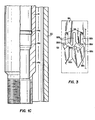
- the reference numeral 10 refers in general to a sliding sleeve valve comprising an upper tubular housing 12 and a lower tubular housing 14 each of which has a stepped outer diameter and inner diameter.
- An intermediate tubular housing 16 extends between the upper housing 12 and the lower housing 14.
- the upper and lower end portions of the upper housing 12 are stepped and are provided with a plurality of external threads to enable the upper end portion to be connected in a string of well tubing (not shown) and to enable the lower end portion to receive and engage an overlapping threaded upper end portion of the intermediate housing 16.
- the lower end portion of the intermediate housing 16 is in threaded engagement with the upper end portion of the lower housing 14 and the lower end portion of the latter housing is externally threaded for connection in the string of well tubing, as will be described.
- the valve 10 is positioned relative to a wellbore casing 20 located in an earth well and having a plurality of axially and angularly spaced perforations 20a. As described in detail later, the valve 10 is normally connected between two sections of production tubing (not shown), and packers, or the like, are spaced above and below the valve 10 to isolate zones in the casing 20 for selective stimulation of the oil and gas reservoirs adjacent the casing or for other similar functions.
- annular packing 22 extends between the lower end of the upper housing 12 and an inwardly-directed annular flange 16a formed on the intermediate housing 16.
- annular packing 24 extends between the upper end of the lower housing 14 and another inwardly-directed annular flange 16b formed on the intermediate housing 16 in a spaced relation to the flange 16a.
- a plurality of angularly-spaced openings 16c are provided through the intermediate housing 16 and extend between the packings 22 and 24.
- the inner bores of the upper housing 12 and the lower housing 14 are shown by the reference numerals 12a and 14a, respectively and are stepped to define a pair of shoulders 12b and 14b and a continuous enlarged bore extending therebetween.
- the latter bore receives a sliding sleeve 26 the outer diameter of which is slightly less than the inner diameter of the enlarged bore and the packings 22 and 24.
- the sleeve 26 is adapted for slidable movement between a closed position shown in Figs. 1A-1C, in which the upper end of the sleeve 26 engages the shoulder 12b, and an open position (shown and further described in connection with Figs. 2A-2D) in which the lower end of the sleeve 26 engages the shoulder 14b.
- annular detents 14c, 14d and 14e are provided in the inner surface of the lower housing 14 and are adapted to be engaged by an annular raised portion 26a formed on the outer surface of the sleeve 26. In the closed portion of Figs. 1A-1C the raised portion 26a extends in the detent 14c.
- a plurality of angularly-spaced openings 26b are provided through the sleeve 26 which, in the closed position of Fig. 1, are axially-spaced from the openings 16c in the intermediate housing 16.
- a plurality of angularly-spaced, relatively small-diameter passages 26c are provided through the sleeve 26 for reasons to be described.
- the sliding sleeve valve 10 is located in the string of well tubing and relative to the casing 20 so that the openings 16c are axially aligned with the perforations 20c in the casing.
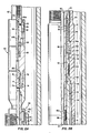
- Figs. 2A-2D depict the entire fluid control assembly of the present invention, including the sliding sleeve valve 10, mounted in the casing 20.
- the sleeve 26 is moved downwardly to its open position in a manner to be described.
- a tubular straddle isolation assembly 30 is then inserted in the bore of the valve 10 in a coaxial relation thereto also in a manner to be described.
- the straddle assembly 30 includes an upper locking mandrel assembly 32, a straddle mandrel 34 connected to the lower end of the mandrel 32, a packing sub 36 connected to the lower end of the straddle mandrel 34, an equalizer sub 38 connected to the lower end of the packing sub 36 and a cap 40 connected to the lower end of the equalizer sub 38.
- All of these components making up the straddle assembly 30 are tubular and thus define a continuous bore which is closed at its lower end by the cap 40. Also, all of these components have stepped inner and outer surfaces and their respective end portions are in a telescoping, or overlapping, relationship and are connected together by cooperating internal and external threads respectively provided thereon and 0-ring seals extending therebetween. Since these type of connections are conventional they will not be described in any further detail.
- the locking mandrel assembly 32 includes a fishing neck 42 having an enlarged end portion 42a and an expander sleeve 44 in threaded engagement with the lower end portion of the fishing neck.
- a portion of the expander sleeve 44 extends within the upper end portion of a locking sleeve 46 having three angularly-spaced elongated openings, or windows, 46a (only one of which is shown).
- Each of the windows 46a receives a locking key 48 having a stepped outer surface which, in the locking position shown, extends through its respective window and into corresponding grooves 12c and 12d formed in the inner bore of the upper housing 12.
- each leaf spring is bent so that its upper portion extends radially in a slot (not shown) formed in the locking sleeve 46 and its lower end portion extends underneath a corresponding key 48 to urge the keys radially outwardly into the locking position shown.
- the expander sleeve 44 can then be moved downwardly to the position shown to lock the keys 48 in the locking position shown.
- a retainer sleeve 50 having a stepped outer surface, receives the expander sleeve 44, the locking sleeve 46 and the keys 48, and is connected, at its lower end portion, to the straddle mandrel 34.
- An annular packing 54 extends between a shoulder defined by the stepped outer surface of the sleeve 50 and the upper end of the straddle mandrel 34, and an annular packing 56 extends between a shoulder defined by a stepped outer surface of the packing sub 36 and the upper end of the equalizer sub 38.
- the packings 54 and 56 are designed to provide a tight fit with the corresponding surface of the side door valve 10 to withstand and seal against relatively high fluid pressures.
- a plurality of angularly-spaced openings 34a are provided through the mandrel 34 which are in axial alignment with the openings 16c in the housing 16 of the side door valve 10 and with the openings 26b of the sleeve 26 in the open position of the sleeve shown in Fig. 2.
- a plurality of angularly-spaced, radially-extending indexing pins 58 extend through an opening in the straddle mandrel 34 in threaded engagement therewith.
- the pins 58 project inwardly into the bore of the mandrel 34 and their function will be described later.
- the equalizer sub 38 has a radial passage 38a extending therethrough which is normally blocked by an equalizer valve 59 having two spaced 0-rings 59a and 59b engaging the inner bore of the sub.
- a plurality of slots are formed in the lower end of the valve 59 to form resilient fingers 59c which normally rest on a beveled internal shoulder 38b of the sub 38.
- the reference numeral 60 refers, in general, to a tubular stinger assembly having a portion extending within the bore of the straddle assembly 30.
- the upper portion of the stinger assembly 60 includes an upper housing 62 having an internally threaded upper end portion for connection to reeled tubing (not shown).
- the housing 62 extends over an inner mandrel 64 having a chamfered end 64a and an annular groove 64b.
- a plurality of shear pins 65 (one of which is shown) extend through angularly-spaced openings formed through the upper housing 62 and into an annular groove formed in the outer surface of the inner mandrel 64 to normally prevent relative axial movement between the housing and the mandrel.
- a valve housing 66 extends over the lower end portion of the upper housing 62, and a plurality of angularly-spaced retaining lugs 68 (one of which is shown) extend from the inner mandrel 64, through corresponding openings found in the upper housing 62 and into an annular groove formed in the inner surface of the valve housing 66.
- the lugs 68 normally prevent axial movement of the upper housing 62 relative to the valve housing 66 but permit an emergency release of same as will be described.
- a ball valve 69 is sized to rest on the chamfered end 64a of the inner mandrel 64 for reasons to be described.
- a fishing neck 70 projects upwardly from the valve housing 66 with its lower end portion in threaded engagement with the upper end portion of the latter housing.
- the upper end portion of a cross-over sub 72 is in threaded engagement with the lower end portion of the valve housing 66, and a valve cage 74 is secured between the lower end of the valve housing 66 and a shoulder formed by a stepped inner surface of the crossover sub 72.
- the body portion of the valve cage 74 is spaced slightly radially outwardly from the corresponding inner surface of the valve housing 66 to define an annular passage P1 and a plurality of openings 74a (one of which is shown in Fig. 2a) in communication with the latter passage.
- the upper end of the valve cage 74 is chamfered for receiving a ball valve 76 which moves between the latter end and a beveled shoulder 66a formed on the inner surface of the valve housing, for reasons that will be explained.
- the stinger assembly 60 also includes a packing sub 80 connected to the lower end portion of the cross-over sub 72, a circulating sub 82 connected to the lower end of the packing sub and a retainer cap 84 extending over the lower end portion of the circulating sub. All of these components are tubular, have stepped inner and outer surfaces, and their respective end portions are in a telescoping, or overlapping relationship and are connected together by cooperating internal and external threads respectively provided thereon. Since these types of connections are conventional they will not be described in any further detail.
- An annular packing 86 is located between the upper end of the circulating sub 82 and a shoulder 80a formed on the packing sub 80.
- a plurality of annular-spaced openings 82a extend through the sub in axial alignment with the openings 34a of the mandrel 34, the openings 16c in the housing 16 of the sliding sleeve valve 10, and with the openings 26b of the sleeve 26 in its open position.
- An indexing sleeve 88 extends between the upper end of the cap 84 and a shoulder 82b defined by the stepped outer surface of the sub 82.
- the inner diameter of the sleeve 88 is slightly greater than the outer diameter of the corresponding portion of the sub 82, and the outer diameter of the sleeve is slightly less than the corresponding portion of inner diameter of the mandrel 34 to permit rotation of the sleeve for reasons to be described.
- a plurality of slots 88a are provided in the lower portion of the sleeve 88 which receive the indexing pins 58 and a plurality of slots 88b are provided in the upper portion of the sleeve 88.
- the sleeve 88 also includes angled cam surfaces 88c and 88d located adjacent the slots 88a and 88b, respectively, for reasons to be described.
- the pins engage the lower cam surfaces 88c, work their way into the grooves 88a (by rotation of the sleeve 88 as necessary), engage the upper cam surfaces 88d and work their way into, and pass through, the grooves 88b until the lower end of the housing 72 bottoms out on the upper end of the fishing neck 42.
- the pins pass back through the grooves 88b, engage the cam surface 88d to cause rotation and orientation of the sleeve 88, and bottom out on the lower ends of the latter grooves, as shown by the dashed lines.
- the casing 20 is shown in Fig. 4 passing through a formation 90 in an earth well 92.
- the reference numerals 94a and 94b refer to an upper section and a lower section, respectively, of a string of well tubing located in the casing 20.
- the sliding sleeve valve 10 is connected between the tubing sections 94a and 94b in the manner described above.
- Two axially-spaced packers 96a and 96b extend between the outer surfaces of the well tubing sections 94a and 94b, respectively, and the inner surface of the casing 20.
- the packers 96a and 96b operate in a conventional manner to anchor and seal the tubing sections 94a and 94b to the casing 20 to form a sealed annular chamber and isolate the perforations 20a in the casing 20 from other axially-spaced perforations (not shown) formed through the casing. In this manner, the fluid stimulation operation to be described can be applied to the perforations 20a.
- the straddle assembly 30 is positioned in the sliding sleeve valve 10 in the manner described above, and the stinger assembly 60 is shown after it has been lowered into the straddle assembly 30.
- the upper end of the stinger assembly 60 is connected, via an adapter 98 to the lower end of a section of reeled tubing 100 which is stored on a reel 102 above ground and is injected into the casing 20 by an injector 104.
- a manifold (not shown) is provided which includes the necessary pumps, valves, and fluid reservoirs to discharge high pressure stimulation fluid into and through the reeled tubing 100.
- a wellhead valve (not shown) is used to control vertical access to and fluid communication with the upper well tubing section 94a and blowout preventers, or the like (not shown), can be installed to block fluid flow during emergency conditions. Since these components are conventional they will not be described in any further detail.
- the sliding sleeve valve 10 is connected between the two well tubing sections 94a and 94b and the assembly is positioned in the wellbore casing 20, as shown in Fig 4, i.e., with the openings 16c of the valve 10 in approximate axial alignment with the perforations 20a in the casing 20.
- the sleeve 26 of the valve 10 is in its closed position shown in Fig. 1B, i.e., with the raised portion 26a of the sleeve 26 in the detent 14c, and the openings 26b axially-spaced from the openings 16c in the intermediate housing 16.
- a shifting tool or the like (not shown), is inserted into the casing 20 by reeled tubing or wireline and is lowered until it extends within the side door valve 10.
- An example of such a shifting tool is disclosed in U.S. Patent No. 3,051,243 to which reference can be made for further details.
- the shifting tool is adapted to engage the sleeve 26 in a conventional manner and the tool is then moved downwardly relative into the side door valve 10 to slide the sleeve downwardly. This downward movement of the sleeve 26 continues until the raised portion 26a engages in the detent 14e and the lower end of the sleeve abutts the shoulder 14b of the housing 14 as shown in Fig. 2D. In this position, the openings 26b of the sleeve 26 are in axial alignment with the openings 16c of the intermediate housing 16.
- the straddle assembly 30 is then connected, above surface, to a suitable running tool, or the like (not shown), the upper end of which is connected to a section of reeled tubing (which may be reeled tubing 100) and the lower end of which is adapted to be quick-releasably connected to the fishing neck 42.
- the running tool can be of the type disclosed in US Patent 4,986,362, issued January 22, 1991, and assigned to the assignee of the present invention.
- the running tool, and therefore the straddle assembly 30, is then inserted into the casing 20 as disclosed in the above-identified application.
- a prong (not shown) associated with the running tool initially enters the straddle assembly 30 and passes through the bore thereof until it engages the upper end of the equalizer valve 59 and forces it downwardly, which causes the shoulder 38b formed on the equalizer sub 38 to cam the fingers 59c radially inwardly to permit the valve to continue to move downwardly until the lower ends of the fingers engage an internal shoulder 38c of the sub 38.
- This slideable movement of the valve 59 exposes the opening 38a, and thus permits any well fluid to flow through the latter opening into the interior of the equalizer sub 38 and pass upwardly through the bore of the straddle assembly 30.
- This fluid can then exit through suitable radial openings (not shown) formed in the fishing neck 42 in order to equalize the pressure across the latter assembly during this downward movement of the assembly 30.
- the assembly 30 then enters the inner bore of the valve 10 and continues until it attains the position shown in Figs. 2A-2D.
- the keys 48 are initially spring biased into the corresponding grooves 12c and 12d.
- the latter sleeve locks the keys 48 in the position shown and prevents further downward movement of the latter neck and sleeve.
- the openings 34a in the mandrel 34 are in alignment with the openings 26b and 16c respectively provided in the sleeve 26 and the housing 16, which openings extend between the packing assemblies 54 and 56.
- the equalizer valve 59 can then be moved back, by the above-mentioned prong, to the position shown in Fig. 2D, i.e. in a position blocking flow through the passage 38a and the prong, along with the above-mentioned running tool, are removed from the wellbore.
- an end of a section of the reeled tubing 100 is then threaded onto the adapter 98 which is also connected to the housing 62 of the stinger assembly 60.
- the assembly 60 and the reeled tubing 100 is pushed through the casing 20 and the well tubing section 94a until it enters the upper end portion of the straddle assembly 30 and continues until the pins 58 pass into and through the appropriate grooves 88a in the sleeve 88.
- the operator then pulls up on the reeled tubing 100 and therefore the stinger assembly 60 and the sleeve 88, which causes the pins 58 to move out of the grooves 88b and take the position shown by the dashed lines in Fig. 3, i.e. with the pins engaging the apex of each of the cam surfaces 88d to lock the stinger assembly 60 against further upward axial movement relative to the straddle assembly 30.
- the openings 82a are in alignment with the openings 34a, 26b and 16c as show in Fig. 2C.
- Pressurized stimulation fluid can then be introduced, via the reeled tubing 100, through the bore of the stinger assembly 60. Flow through the assembly is blocked by the end cap 40 of the straddle assembly 30 and the packings 54, 56 and 86. Thus, the fluid passes radially through the aligned openings 82a, 34a, 26b and 16c before discharging into the annulus defined between the outer surface of the side door valve 10 and the inner surface of the casing 20. The fluid then will pass through the perforations 20a and into the formation 90 to stimulate same.
- the ball valve 76 is forced against the end of the cage 74 by the stimulation fluid as it passes around the ball and through the opening 74a.
- the force of this pressure drives the ball valve 76 against the shoulder 66a to block any further flow upwardly, and thus prevent possible backflow towards the surface.
- the valve 76 is not used.
- the ball valve 69 is dropped into the reeled tubing and is forced against the end 64a of the inner mandrel 64 under the pressure of the fluid from the reeled tubing.
- the latter pressure thus builds up against the ball valve 69, and when this pressure is sufficient to exert a force sufficient to shear the pins 65, the sleeve 64 moves downwardly until the groove 64b aligns with the lugs 68. This permits the lugs 68 to move into the groove 64b, thus releasing the housing 62 from the housing 66 and permitting a quick disconnect of the housing 62 and therefore the reeled tubing 100 from the stinger assembly 60.
- a plurality of circulating holes are provided through the housing 62, which are axially aligned with, and angularly spaced from, the holes receiving the shear pins 65, to allow for circulation of fluid through the reeled tubing 100 while the latter is being removed from the well.
- Removal of the housing 62 exposes the fishing neck 70 which allows a heavy duty workstring (not shown), which may include a pulling tool, an accelerator and a hydraulic jar, to be attached to a reeled tubing and lowered into the casing 20 until the pulling tool engages the fishing neck.
- a pulling operation can be performed on the stinger assembly 60.
- the above-described operation is reversed.
- the stinger assembly 60 is initially removed from the straddle assembly 30 by pushing down on the reeled tubing, and therefore the sleeve 88, to cause the sleeve to rotate against the pins 58 and align the slots 88a with the pins so that the sleeve 88, and therefore the stinger assembly, can be released from the straddle assembly by pulling up on the reeled tubing.
- a pulling tool (not shown) is then connected to the reeled tubing and lowered into the casing until it engages the fishing neck 42 of the locking mandrel assembly 32 to permit the straddle assembly 30 to be removed.
- An example of a suitable pulling tool for the purpose is described in our UK patent application GB 2231359A published November 14, 1990.
- a prong associated with the pulling tool can move the valve 59 downwardly to equalize the pressure.
- the sleeve 26 of the valve 10 is then moved upwardly to its closed position by the shifting tool described above using reeled tubing. During this movement of the sleeve 26, it can be stopped in an intermediate position in which the raised portion 26a engages in the middle detent 14d. In this position, the passages 26c are in alignment with the opening 16c in the intermediate housing 16 to permit any well fluid to flow therethrough and equalize the pressure of the fluid. This is done when the sleeve 26 is closed, and equalization is needed prior to opening.
- the system, assembly and method of the present invention provide an efficient and reliable technique for directing stimulation fluid into and through the perforations in the casing 20 while effectively isolating same from leakage and preventing blow-out.
Landscapes
- Engineering & Computer Science (AREA)
- Geology (AREA)
- Life Sciences & Earth Sciences (AREA)
- Mining & Mineral Resources (AREA)
- Environmental & Geological Engineering (AREA)
- Fluid Mechanics (AREA)
- Physics & Mathematics (AREA)
- General Life Sciences & Earth Sciences (AREA)
- Geochemistry & Mineralogy (AREA)
- Mechanical Engineering (AREA)
- Quick-Acting Or Multi-Walled Pipe Joints (AREA)
- Safety Valves (AREA)
- Sliding Valves (AREA)
Claims (16)
- Fluidflußsteuerungsanordnung mit einer Gleithülsenschieberanordnung, die ein röhrenförmiges Gehäuse (12,14,16) mit einer sich durch dieses hindurch erstreckenden radialen Öffnung (16c), eine Einrichtung zum Verbinden des genannten Gehäuses in ein Bohrlochrohr und eine Hülse (26) umfaßt, die sich innerhalb des genannten Gehäuses erstreckt und eine sich durch dieses hindurch erstreckende radiale Öffnung (26b) aufweist, wobei die genannte Hülse relativ zum genannten Gehäuse in eine und aus einer Position gleiten kann, in der die genannten Öffnungen aufeinander ausgerichtet sind, gekennzeichnet durch(a) eine röhrenförmige Überspannanordnung (30) zum Einschieben in die genannte Hülsenschieberanordnung, und die eine sich durch sie hindurch erstreckende radiale Öffnung (34a) zur Ausrichtung mit den genannten Öffnungen in der genannten Hülsenschieberanordnung aufweist;(b) axial beabstandete Abdichtungseinrichtungen (54,56), die sich zwischen der Außenfläche der genannten überspannanordnung und der Innenfläche der genannten Hülsenschieberanordnung erstrecken und sich in dichtendem Eingriff damit befinden, wobei die genannte radiale Öffnung (34a) in der Überspannanordnung zwischen den genannten Abdichtungseinrichtungen angeordnet ist;(c) eine Vorschubstangenanordnung (60) mit einer Einrichtung (62) zum Anschließen eines Endes der genannten Vorschubstangenanordnung an aufgerollte Verrohrung zum Einschieben in die genannte Überspannanordnung, wobei die genannte Vorschubstangenanordnung eine sich durch sie hindurch erstreckende radiale Öffnung (82a) aufweist, die mit den genannten Öffnungen in der genannten Hülsenschieberanordnung und der genannten Überspannanordnung in Ausrichtung ist; und(d) eine Arretiereinrichtung (58), die der genannten Vorschubstangenanordnung (60) und der genannten Überspannanordnung (30) zugeordnet ist, um axiale Bewegung dazwischen zu verhindern;wodurch Fluidfluß aufgrund der genannten Abdichtungseinrichtungen durch die genannten ausgerichteten Öffnungen und zwischen die genannte aufgerollte Verrohrung und den Raum zwischen der genannten Hülsenschieberanordnung und dem genannten Bohrlochrohr gelenkt wird.
- Anordnung nach Anspruch 1, worin die genannte Hülse (26) aus einer offenen Position in eine Position gleiten kann, die den Fluß des genannten Fluids durch die genannten Öffnungen (16c,26b,34a,82a) versperrt.
- Anordnung nach einem der vorhergehenden Ansprüche, worin die genannte Überspannanordnung (30) umfaßt:
einen Dorn (34), durch den sich die genannte radiale Öffnung (34a) erstreckt;
eine Einrichtung zum Verbinden des genannten Dorns mit einem Werkzeug zum Einschieben des genannten Dorns in das genannte Gehäuse (12,14,16) bei Ausrichtung der genannten Öffnung im genannten Dorn mit der genannten Öffnung (16c) im genannten Gehäuse;
axial beabstandete Abdichtungseinrichtungen (54,56), die auf dem genannten Dorn getragen werden und sich in dichtendem Eingriff damit zwischen der Außenfläche des genannten Dorns und der Innenfläche des genannten Gehäuses erstrecken, wobei die genannte Öffnung im genannten Dorn zwischen der genannten Abdichtungseinrichtung angeordnet ist; und
eine Einrichtung (40), um den Fluß eines Fluids axial durch den genannten Dorn zu verhindern. - Anordnung nach Anspruch 3, worin die genannte Vorschubstangenanordnung (60) einen röhrenförmigen Einsatz (82) mit einer sich durch diesen hindurch erstreckenden radialen Öffnung (82a) umfaßt; sowie
eine Einrichtung (62) zum Verbinden eines Endes des genannten Einsatzes mit der aufgerollten Verrohrung (100) zum Einschieben zumindest eines Abschnitts des genannten Einsatzes in den genannten Dorn (34), wobei die genannte Öffnung (82a) im genannten Einsatz sich in Ausrichtung mit den genannten Öffnungen (34a,16c) im genannten Dorn und genannten Gehäuse befindet. - Anordnung nach Anspruch 4, worin die genannte Arretiereinrichtung (58), die der genannten Vorschubstangenanordnung (60) und der genannten Überspannanordnung (30) zugeordnet ist, dem genannten Dorn (34) der genannten Überspannanordnung und dem genannten Einsatz (82) der genannten Vorschubstangenanordnung zugeordnet ist, um axiale Bewegung zwischen dem genannten Dorn und dem genannten Einsatz zu verhindern.
- Anordnung nach Anspruch 5, worin die genannte Arretiereinrichtung eine drehbare Hülse (88), die auf dem genannten Einsatz montiert ist und zumindest eine Rille (88a,88b) definiert, sowie einen Bolzen (58) umfaßt, der mit dem genannten Dorn verbunden ist und sich in die genannte Rille erstreckt.
- Anordnung nach Anspruch 4, die weiters eine dem genannten röhrenförmigen Einsatz zugeordnete Ventileinrichtung zur Steuerung des Flusses von Fluid aus dem Bohrloch durch die genannte Anordnung umfaßt.
- Anordnung nach einem der vorhergehenden Ansprüche, worin die genannte Abdichtungseinrichtung eine erste und eine zweite Dichtungsanordnung umfaßt, die in einer axial beabstandeten Beziehung angeordnet sind, wobei die genannten ausgerichteten Öffnungen sich zwischen den genannten Dichtungsanordnungen befinden.
- Im genannten Bohrlochrohr angeschlossene Fluidflußsteuerungsanordnung nach einem der vorhergehenden Ansprüche, wobei die genannte Vorschubstangenanordnung (60) mit aufgerollter Verrohrung (100) verbunden ist.
- System zur Verwendung einer Anordnung nach einem der Ansprüche 1 bis 8, um Fluidfluß in einem Bohrloch zu steuern, umfassend ein in einem Erdbohrloch angeordnetes Gehäuse (20) mit sich angrenzend an eine Formation (90) im genannten Erdbohrloch durch dieses hindurch erstreckenden Perforationen (20a), einen Bohrlochverrohrungsstrang, obere und untere Einfachschieber (96a,96b) zum Abdichten der genannten Verrohrung im genannten Gehäuse, um eine abgedichtete ringförmige Kammer zwischen dem genannten Gehäuse und der genannten Verrohrung in Verbindung mit der genannten Formation zu bilden, eine mit der genannten Verrohrung verbundene Fluidflußsteuerungsanordnung nach einem der Ansprüche 1 bis 8, die sich zwischen den genannten Einfachschiebern erstreckt und eine sich durch sie hindurch erstreckende radiale Öffnung aufweist.
- System nach Anspruch 10, worin die genannte Abdichtungseinrichtung erste und zweite in axial beabstandeter Beziehung angeordnete Dichtungsanordnungen umfaßt, und worin die genannten ausgerichteten Öffnungen zwischen den genannten Dichtungsanordnungen angeordnet sind.
- Anordnung nach einem der Ansprüche 1 bis 7 oder System nach einem der Ansprüche 10 oder 11, die/das weiters eine der genannten Vorschubstangenanordnung zugeordnete Ventileinrichtung zur Steuerung des Flusses von Fluid aus dem Bohrloch durch die genannte Anordnung umfaßt.
- Anordnung nach einem der Ansprüche 1 bis 8 oder System nach einem der Ansprüche 10 bis 12, die/das weiters eine auf Fluiddruck ansprechende Einrichtung (64,64b,65,68,69) umfaßt, um die genannte aufgerollte Verrohrung vom genannten Einsatz zu trennen.
- Anordnung nach einem der Ansprüche 1 bis 5 oder System nach einem der Ansprüche 10 bis 13, worin die genannte Arretiereinrichtung eine drehbare Hülse (88) umfaßt, die auf der genannten Vorschubstangenanordnung montiert ist und zumindest eine Rille (88a,88b) definiert, sowie einen Bolzen (58), der mit der genannten Überspannanordnung verbunden ist und sich in die genannte Hülse erstreckt.
- Verfahren zur Steuerung des Flusses von Fluid zwischen der aufgerollten Verrohrung (100) und einem Bohrlochrohr durch die Fluidsteuerungsanordnung nach Anspruch 1, wobei das genannte Verfahren die Schritte des Einschiebens einer Gleithülsenschieberanordnung in das genannte Bohrlochrohr umfaßt, wobei die genannte Schieberanordnung eine sich durch sie erstreckende radiale Öffnung (26b) aufweist, gekennzeichnet durch:(a) das Einschieben einer Überspanneinrichtung (30) in die genannte Hülsenschieberanordnung, wobei eine Öffnung (34a) in der genannten Überspannanordnung sich in Ausrichtung mit der genannten Öffnung (26b) in der genannten Hülsenschieberanordnung befindet;(b) das Vorsehen zweier beabstandeter Dichtungen (54,56) auf der genannten Überspannanordnung, die sich zwischen der Außenfläche der genannten Überspannanordnung und der Innenfläche der genannten Hülsenschieberanordnung erstrecken und in dichtendem Eingriff damit befinden, wobei die genannten ausgerichteten Öffnungen sich zwischen den genannten Dichtungen erstrecken;(c) das Anschließen eines Endes einer Vorschubstangenanordnung (60) an die genannte aufgerollte Verrohrung (100), um zumindest einen Abschnitt der genannten Vorschubstangenanordnung in die genannte Überspannanordnung einzuschieben, wobei eine Öffnung (82a) in der genannten Vorschubstangenanordnung sich in Ausrichtung mit den genannten ausgerichteten Öffnungen befindet;(d) das Verhindern des Flusses des genannten Fluids axial durch die genannte Überspannanordnung; und(e) das Arretieren der genannten Vorschubstangenanordnung und der genannten Überspannanordnung gegen relative axiale Bewegung;wodurch Fluidfluß aufgrund der genannten Dichtungseinrichtung durch die genannten ausgerichteten Öffnungen zwischen der genannten aufgerollten Verrohrung und den Raum zwischen dem genannten Gehäuse und dem genannten Bohrlochrohr gelenkt wird.
- Verfahren nach Anspruch 15, das weiters den Schritt des selektiven Zulassens oder Verhinderns des Flusses von Fluid aus dem Bohrloch zwischen dem Äußeren und dem Inneren der genannten Überspannanordnung umfaßt.
Applications Claiming Priority (2)
| Application Number | Priority Date | Filing Date | Title |
|---|---|---|---|
| US508895 | 1983-06-28 | ||
| US07/508,895 US5012871A (en) | 1990-04-12 | 1990-04-12 | Fluid flow control system, assembly and method for oil and gas wells |
Publications (3)
| Publication Number | Publication Date |
|---|---|
| EP0452033A2 EP0452033A2 (de) | 1991-10-16 |
| EP0452033A3 EP0452033A3 (en) | 1992-03-11 |
| EP0452033B1 true EP0452033B1 (de) | 1994-06-22 |
Family
ID=24024496
Family Applications (1)
| Application Number | Title | Priority Date | Filing Date |
|---|---|---|---|
| EP91302933A Expired - Lifetime EP0452033B1 (de) | 1990-04-12 | 1991-04-03 | Flüssigkeitssteuerungssystem, Einrichtung und Verfahren für Erdgas- und Ölbohrungen |
Country Status (4)
| Country | Link |
|---|---|
| US (1) | US5012871A (de) |
| EP (1) | EP0452033B1 (de) |
| CA (1) | CA2037791A1 (de) |
| MY (1) | MY104639A (de) |
Families Citing this family (34)
| Publication number | Priority date | Publication date | Assignee | Title |
|---|---|---|---|---|
| US5203412A (en) * | 1990-07-24 | 1993-04-20 | Glenn Doggett | Well completion tool |
| GB9117119D0 (en) * | 1991-08-08 | 1991-09-25 | Exploration And Production Nor | Tubing test valve |
| US5168931A (en) * | 1991-09-30 | 1992-12-08 | Halliburton Company | Fluid control valve |
| US5285850A (en) * | 1991-10-11 | 1994-02-15 | Halliburton Company | Well completion system for oil and gas wells |
| US5383520A (en) * | 1992-09-22 | 1995-01-24 | Halliburton Company | Coiled tubing inflatable packer with circulating port |
| US5355959A (en) * | 1992-09-22 | 1994-10-18 | Halliburton Company | Differential pressure operated circulating and deflation valve |
| US5343956A (en) * | 1992-12-30 | 1994-09-06 | Baker Hughes Incorporated | Coiled tubing set and released resettable inflatable bridge plug |
| CA2116301A1 (en) * | 1993-02-24 | 1994-08-25 | Robert A. Rademaker | Flow control assembly for coiled tubing |
| US5366019A (en) * | 1993-03-30 | 1994-11-22 | Ctc International | Horizontal inflatable tool |
| US5358048A (en) * | 1993-04-27 | 1994-10-25 | Ctc International | Hydraulic port collar |
| US5411085A (en) * | 1993-11-01 | 1995-05-02 | Camco International Inc. | Spoolable coiled tubing completion system |
| US5479989A (en) * | 1994-07-12 | 1996-01-02 | Halliburton Company | Sleeve valve flow control device with locator shifter |
| US5695009A (en) * | 1995-10-31 | 1997-12-09 | Sonoma Corporation | Downhole oil well tool running and pulling with hydraulic release using deformable ball valving member |
| US5636694A (en) * | 1995-04-27 | 1997-06-10 | Baker Hughes Incorporated | Hydraulic power stroker for shifting of sliding sleeves |
| US5730224A (en) * | 1996-02-29 | 1998-03-24 | Halliburton Energy Services, Inc. | Slidable access control device for subterranean lateral well drilling and completion |
| EP0888491A1 (de) * | 1996-03-22 | 1999-01-07 | Smith International, Inc. | Hydraulische seitentürschiebehülse |
| AU8385498A (en) * | 1997-07-10 | 1999-02-08 | Camco International, Inc. | Single-phase annulus-operated sliding sleeve |
| US6763892B2 (en) | 2001-09-24 | 2004-07-20 | Frank Kaszuba | Sliding sleeve valve and method for assembly |
| US6755628B1 (en) * | 2002-07-16 | 2004-06-29 | Howell's Well Service, Inc. | Valve body for a traveling barrel pump |
| US6675909B1 (en) | 2002-12-26 | 2004-01-13 | Jack A. Milam | Hydraulic jar |
| US8230912B1 (en) | 2009-11-13 | 2012-07-31 | Thru Tubing Solutions, Inc. | Hydraulic bidirectional jar |
| US9140097B2 (en) | 2010-01-04 | 2015-09-22 | Packers Plus Energy Services Inc. | Wellbore treatment apparatus and method |
| CN101818630B (zh) * | 2010-04-28 | 2012-09-05 | 金湖富源机械有限公司 | 机械式欠平衡井下套管阀 |
| WO2012037645A1 (en) | 2010-09-22 | 2012-03-29 | Packers Plus Energy Services Inc. | Wellbore frac tool with inflow control |
| EP2619405A1 (de) | 2010-09-23 | 2013-07-31 | Packers Plus Energy Services Inc. | Vorrichtung und verfahren zur verarbeitung von flüssigkeiten aus einem brunnen |
| EP2640930A1 (de) | 2010-11-19 | 2013-09-25 | Packers Plus Energy Services Inc. | Kobe-sub, bohrlochrohrstrang und verfahren |
| US8550155B2 (en) | 2011-03-10 | 2013-10-08 | Thru Tubing Solutions, Inc. | Jarring method and apparatus using fluid pressure to reset jar |
| US8657007B1 (en) | 2012-08-14 | 2014-02-25 | Thru Tubing Solutions, Inc. | Hydraulic jar with low reset force |
| WO2015041712A1 (en) * | 2013-09-23 | 2015-03-26 | Geodynamics, Inc. | Selective downhole fluid communication |
| US20150114716A1 (en) * | 2013-10-31 | 2015-04-30 | Smith International, Inc. | Vibration tool |
| WO2015134014A1 (en) * | 2014-03-05 | 2015-09-11 | Halliburton Energy Services Inc. | Flow control mechanism for downhole tool |
| US9428991B1 (en) * | 2014-03-16 | 2016-08-30 | Elie Robert Abi Aad | Multi-frac tool |
| CN105804693B (zh) * | 2015-12-16 | 2017-07-25 | 中国石油化工股份有限公司 | 一种环空安全阀 |
| US10260314B2 (en) * | 2016-06-23 | 2019-04-16 | Vertice Oil Tools | Methods and systems for a pin point frac sleeves system |
Citations (1)
| Publication number | Priority date | Publication date | Assignee | Title |
|---|---|---|---|---|
| US4848463A (en) * | 1988-11-09 | 1989-07-18 | Halliburton Company | Surface read-out tester valve and probe |
Family Cites Families (48)
| Publication number | Priority date | Publication date | Assignee | Title |
|---|---|---|---|---|
| US1927836A (en) * | 1931-02-03 | 1933-09-26 | Frank J Kightlinger | Rotary jar |
| US2499695A (en) * | 1947-03-18 | 1950-03-07 | Lynn W Storm | Jar |
| US2901045A (en) * | 1953-04-20 | 1959-08-25 | Otis Eng Co | Locking means for well tools |
| US2851110A (en) * | 1954-08-31 | 1958-09-09 | Independent Tool Company | Well jars |
| US2828822A (en) * | 1955-01-31 | 1958-04-01 | Independent Tool Company | Well jar |
| US3051239A (en) * | 1958-04-21 | 1962-08-28 | Otis Eng Co | Running and pulling tool |
| US3051243A (en) * | 1958-12-12 | 1962-08-28 | George G Grimmer | Well tools |
| US3088533A (en) * | 1959-04-27 | 1963-05-07 | Wayne N Sutliff | Sleeve valve and oil well tool embodying the same |
| US3079996A (en) * | 1959-04-30 | 1963-03-05 | Sun Oil Co | Flow control devices for flow conductors |
| US3208531A (en) * | 1962-08-21 | 1965-09-28 | Otis Eng Co | Inserting tool for locating and anchoring a device in tubing |
| US3393002A (en) * | 1965-03-23 | 1968-07-16 | Brown J. Woolley | Overshot retrieving tool |
| US3405773A (en) * | 1966-08-05 | 1968-10-15 | Wayne N. Sutliff | Sleeve valve and oil well tool embodying the same |
| US3944273A (en) * | 1974-06-03 | 1976-03-16 | Vetco Offshore Industries, Inc. | Retrieving tool for wellhead packing |
| US3946819A (en) * | 1975-01-27 | 1976-03-30 | Brown Equipment & Service Tools, Inc. | Well tool and method of use therefor |
| CA1005810A (en) * | 1975-03-03 | 1977-02-22 | Jarco Services Ltd. | Drill string jarring and bumping tool with piston disconnect |
| US4093294A (en) * | 1975-06-04 | 1978-06-06 | Taylor William T | Releasable wireline spear |
| US4185865A (en) * | 1975-06-04 | 1980-01-29 | Taylor William T | Releasable wireline overshot |
| US4186807A (en) * | 1977-12-20 | 1980-02-05 | Downen Jim L | Optional up-blow, down-blow jar tool |
| US4161224A (en) * | 1978-02-10 | 1979-07-17 | Halliburton Company | Fluid dump mechanism |
| US4179002A (en) * | 1978-08-25 | 1979-12-18 | Dresser Industries, Inc. | Variable hydraulic resistor jarring tool |
| US4181186A (en) * | 1978-09-05 | 1980-01-01 | Dresser Industries, Inc. | Sleeve valve hydraulic jar tool |
| US4346770A (en) * | 1980-10-14 | 1982-08-31 | Halliburton Company | Hydraulic jarring tool |
| US4361195A (en) * | 1980-12-08 | 1982-11-30 | Evans Robert W | Double acting hydraulic mechanism |
| US4396061A (en) * | 1981-01-28 | 1983-08-02 | Otis Engineering Corporation | Locking mandrel for a well flow conductor |
| US4558895A (en) * | 1981-02-11 | 1985-12-17 | Otis Engineering Corporation | Pulling tool |
| US4436150A (en) * | 1981-09-28 | 1984-03-13 | Otis Engineering Corporation | Bridge plug |
| US4456081A (en) * | 1982-08-02 | 1984-06-26 | Newman James L | Hydraulic drilling jar |
| US4515220A (en) * | 1983-12-12 | 1985-05-07 | Otis Engineering Corporation | Apparatus and method for rotating coil tubing in a well |
| US4614233A (en) * | 1984-10-11 | 1986-09-30 | Milton Menard | Mechanically actuated downhole locking sub |
| US4682657A (en) * | 1985-02-14 | 1987-07-28 | Crawford James B | Method and apparatus for the running and pulling of wire-line tools and the like in an oil or gas well |
| US4612984A (en) * | 1985-02-14 | 1986-09-23 | Crawford James B | Apparatus for the running and pulling of wire-line tools and the like in an oil or gas well |
| US4646830A (en) * | 1985-04-22 | 1987-03-03 | Templeton Charles A | Mechanical jar |
| US4625799A (en) * | 1985-06-19 | 1986-12-02 | Otis Engineering Corporation | Cleaning tool |
| US4794989A (en) * | 1985-11-08 | 1989-01-03 | Ava International Corporation | Well completion method and apparatus |
| US4685516A (en) * | 1986-01-21 | 1987-08-11 | Atlantic Richfield Company | Apparatus for operating wireline tools in wellbores |
| US4784225A (en) * | 1986-03-26 | 1988-11-15 | Shell Offshore Inc. | Well valve assembly method and apparatus |
| US4869325A (en) * | 1986-06-23 | 1989-09-26 | Baker Hughes Incorporated | Method and apparatus for setting, unsetting, and retrieving a packer or bridge plug from a subterranean well |
| US4796707A (en) * | 1986-06-23 | 1989-01-10 | Baker Hughes Incorporated | Apparatus for setting, unsetting, and retrieving a packer or bridge plug from a subterranean well |
| US4805699A (en) * | 1986-06-23 | 1989-02-21 | Baker Hughes Incorporated | Method and apparatus for setting, unsetting, and retrieving a packer or bridge plug from a subterranean well |
| US4708208A (en) * | 1986-06-23 | 1987-11-24 | Baker Oil Tools, Inc. | Method and apparatus for setting, unsetting, and retrieving a packer from a subterranean well |
| US4767145A (en) * | 1986-10-06 | 1988-08-30 | Otis Engineering Corporation | Running and pulling tool |
| US4715445A (en) * | 1986-12-09 | 1987-12-29 | Hughes Tool Company | Latch and retrieving assembly |
| US4759406A (en) * | 1987-02-25 | 1988-07-26 | Atlantic Richfield Company | Wireline tool connector with wellbore fluid shutoff valve |
| US4793417A (en) * | 1987-08-19 | 1988-12-27 | Otis Engineering Corporation | Apparatus and methods for cleaning well perforations |
| US4844166A (en) * | 1988-06-13 | 1989-07-04 | Camco, Incorporated | Method and apparatus for recompleting wells with coil tubing |
| US4862958A (en) * | 1988-11-07 | 1989-09-05 | Camco, Incorporated | Coil tubing fluid power actuating tool |
| US4928772A (en) * | 1989-02-09 | 1990-05-29 | Baker Hughes Incorporated | Method and apparatus for shifting a ported member using continuous tubing |
| US4915175A (en) * | 1989-02-21 | 1990-04-10 | Otis Engineering Corporation | Well flow device |
-
1990
- 1990-04-12 US US07/508,895 patent/US5012871A/en not_active Expired - Fee Related
-
1991
- 1991-03-08 CA CA002037791A patent/CA2037791A1/en not_active Abandoned
- 1991-03-14 MY MYPI91000418A patent/MY104639A/en unknown
- 1991-04-03 EP EP91302933A patent/EP0452033B1/de not_active Expired - Lifetime
Patent Citations (1)
| Publication number | Priority date | Publication date | Assignee | Title |
|---|---|---|---|---|
| US4848463A (en) * | 1988-11-09 | 1989-07-18 | Halliburton Company | Surface read-out tester valve and probe |
Also Published As
| Publication number | Publication date |
|---|---|
| CA2037791A1 (en) | 1991-10-13 |
| EP0452033A2 (de) | 1991-10-16 |
| MY104639A (en) | 1994-04-30 |
| EP0452033A3 (en) | 1992-03-11 |
| US5012871A (en) | 1991-05-07 |
Similar Documents
| Publication | Publication Date | Title |
|---|---|---|
| EP0452033B1 (de) | Flüssigkeitssteuerungssystem, Einrichtung und Verfahren für Erdgas- und Ölbohrungen | |
| CA2153643C (en) | Sleeve valve flow control device with locator shifter | |
| US5285850A (en) | Well completion system for oil and gas wells | |
| US6666275B2 (en) | Bridge plug | |
| US5090481A (en) | Fluid flow control apparatus, shifting tool and method for oil and gas wells | |
| CA2087673C (en) | Perforating type lockout tool | |
| CA2080970C (en) | Short stroke casing valve with positioning and jetting tools therefor | |
| US5823265A (en) | Well completion system with well control valve | |
| AU737708B2 (en) | Valve operating mechanism | |
| US6997252B2 (en) | Hydraulic setting tool for packers | |
| US5511617A (en) | Apparatus and method for temporarily plugging a tubular | |
| US6997263B2 (en) | Multi zone isolation tool having fluid loss prevention capability and method for use of same | |
| US4949793A (en) | Method and apparatus for completion of a well | |
| US6634429B2 (en) | Upper zone isolation tool for intelligent well completions | |
| US8037938B2 (en) | Selective completion system for downhole control and data acquisition | |
| CA1265440A (en) | Subsurface injection tool | |
| CA2445870C (en) | Automatic tubing filler | |
| US4969524A (en) | Well completion assembly | |
| US4682656A (en) | Completion apparatus and method for gas lift production | |
| US5330000A (en) | Squeeze packer latch | |
| US20020070028A1 (en) | Debris free valve apparatus | |
| EP1828538B1 (de) | Verfahren und vorrichtung zur flüssigkeitsumgehung eines bohrwerkzeugs | |
| GB2281331A (en) | Apparatus for actuating sliding member of downhole tool | |
| US20110114321A1 (en) | Open/Close Outlet Internal Hydraulic Device | |
| EP0969181A2 (de) | Verteilerapparat |
Legal Events
| Date | Code | Title | Description |
|---|---|---|---|
| PUAI | Public reference made under article 153(3) epc to a published international application that has entered the european phase |
Free format text: ORIGINAL CODE: 0009012 |
|
| AK | Designated contracting states |
Kind code of ref document: A2 Designated state(s): GB IT NL |
|
| PUAL | Search report despatched |
Free format text: ORIGINAL CODE: 0009013 |
|
| AK | Designated contracting states |
Kind code of ref document: A3 Designated state(s): GB IT NL |
|
| 17P | Request for examination filed |
Effective date: 19920803 |
|
| 17Q | First examination report despatched |
Effective date: 19921002 |
|
| GRAA | (expected) grant |
Free format text: ORIGINAL CODE: 0009210 |
|
| AK | Designated contracting states |
Kind code of ref document: B1 Designated state(s): GB IT NL |
|
| RAP2 | Party data changed (patent owner data changed or rights of a patent transferred) |
Owner name: HALLIBURTON COMPANY |
|
| ITF | It: translation for a ep patent filed | ||
| PLBE | No opposition filed within time limit |
Free format text: ORIGINAL CODE: 0009261 |
|
| STAA | Information on the status of an ep patent application or granted ep patent |
Free format text: STATUS: NO OPPOSITION FILED WITHIN TIME LIMIT |
|
| 26N | No opposition filed | ||
| PG25 | Lapsed in a contracting state [announced via postgrant information from national office to epo] |
Ref country code: NL Effective date: 19951101 |
|
| NLV4 | Nl: lapsed or anulled due to non-payment of the annual fee |
Effective date: 19951101 |
|
| REG | Reference to a national code |
Ref country code: GB Ref legal event code: IF02 |
|
| PGFP | Annual fee paid to national office [announced via postgrant information from national office to epo] |
Ref country code: GB Payment date: 20020404 Year of fee payment: 12 |
|
| PG25 | Lapsed in a contracting state [announced via postgrant information from national office to epo] |
Ref country code: GB Free format text: LAPSE BECAUSE OF NON-PAYMENT OF DUE FEES Effective date: 20030403 |
|
| GBPC | Gb: european patent ceased through non-payment of renewal fee |
Effective date: 20030403 |
|
| PG25 | Lapsed in a contracting state [announced via postgrant information from national office to epo] |
Ref country code: IT Free format text: LAPSE BECAUSE OF NON-PAYMENT OF DUE FEES Effective date: 20050403 |