EP0451825B1 - Multi-transmission method and multi-transmission system for a vehicle - Google Patents
Multi-transmission method and multi-transmission system for a vehicle Download PDFInfo
- Publication number
- EP0451825B1 EP0451825B1 EP19910105705 EP91105705A EP0451825B1 EP 0451825 B1 EP0451825 B1 EP 0451825B1 EP 19910105705 EP19910105705 EP 19910105705 EP 91105705 A EP91105705 A EP 91105705A EP 0451825 B1 EP0451825 B1 EP 0451825B1
- Authority
- EP
- European Patent Office
- Prior art keywords
- transmission
- high speed
- low speed
- data
- vehicle
- Prior art date
- Legal status (The legal status is an assumption and is not a legal conclusion. Google has not performed a legal analysis and makes no representation as to the accuracy of the status listed.)
- Revoked
Links
Images

Classifications
-
- B—PERFORMING OPERATIONS; TRANSPORTING
- B60—VEHICLES IN GENERAL
- B60R—VEHICLES, VEHICLE FITTINGS, OR VEHICLE PARTS, NOT OTHERWISE PROVIDED FOR
- B60R16/00—Electric or fluid circuits specially adapted for vehicles and not otherwise provided for; Arrangement of elements of electric or fluid circuits specially adapted for vehicles and not otherwise provided for
- B60R16/02—Electric or fluid circuits specially adapted for vehicles and not otherwise provided for; Arrangement of elements of electric or fluid circuits specially adapted for vehicles and not otherwise provided for electric constitutive elements
- B60R16/03—Electric or fluid circuits specially adapted for vehicles and not otherwise provided for; Arrangement of elements of electric or fluid circuits specially adapted for vehicles and not otherwise provided for electric constitutive elements for supply of electrical power to vehicle subsystems or for
- B60R16/0315—Electric or fluid circuits specially adapted for vehicles and not otherwise provided for; Arrangement of elements of electric or fluid circuits specially adapted for vehicles and not otherwise provided for electric constitutive elements for supply of electrical power to vehicle subsystems or for using multiplexing techniques
- B60R2016/0322—Temporary code for documents to be reclassified to G08C, H04L or H04Q
Definitions
- the present invention relates to a multi-transmission method and a multi-transmission system for us in a vehicle for transmitting signals through bus lines and a multi-transmission terminal which are provided in various places in a vehicle for data communication.
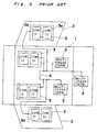
- FIG. 2 A prior art system for multi-transmission data in a vehicle is shown in Fig. 2.
- the prior art multi-transmission system has a plurality of multi-transmission terminals 3 equipped in a vehicle compartment 1 and vehicle doors 2.
- Each multi-transmission terminal 3, defined by an electronic control (EC) unit has a transmission control circuit 3a and a transmission interface 3b, and is disposed in various places in the vehicle compartment 1 and also in vehicle doors 2.
- the multi-transmission terminals 3 are connected to a high speed bus line 4.
- Various loads provided in the vehicle are controlled in such a manner that, by the operation of a control switch equipped in the vicinity of a driver seat, an operation signal is generated which is input to the multi-transmission terminal 3 near the driver seat and is transmitted to the multi-transmission terminal 3 near the load to be controlled through a high speed bus line 4. And then, the operation signal is transmitted to the load to be controlled, thereby controlling the load.
- conditions of various loads are displayed on a monitor panel positioned near the driver seat in such a manner that, a detection signal generated by a detection sensor is input to the multi-transmission terminal 3 near the load and the detection signal is multi-transmitted to the multi-transmission terminal 3 near the driver seat through the bus line 4 from the multi-transmission terminal 3 near the load so as to display the condition of the load on the monitor panel.
- bus line 4 is used for mutually transmitted signals among the loads in a similar manner as that mentioned above.
- each of the multi-transmission terminals 3 is provided with a communication function based on a predetermined protocol.
- the transmission speed is set to be the same as the response speed of the load which generally requires a high response speed.
- the delay time is usually set to be about 10 msec.
- one master terminal is provided in a vehicle compartment and is connected to each of terminals at the various places in the vehicle in a star connection structure.
- the loads which do not require a high speed data transmission but operate sufficiently with a relatively slow speed e.g., 50 msec, such as a power window motor or mirror motor provided in the door
- a relatively slow speed e.g. 50 msec
- the loads which do not require a high speed data transmission but operate sufficiently with a relatively slow speed e.g., 50 msec, such as a power window motor or mirror motor provided in the door
- high speed communication function with a delay time of 10 msec as in the same manner as those provided in the high speed response loads.
- the object of the present invention is therefore to provide an improved multi-transmission system and a multi-transmission method which solves these problems.
- a conventional method for multi-transmission in a vehicle comprises the steps of ; connecting mutually to each other, through a high speed bus line, a plurality of multi-transmission terminals each of which is equipped in a vehicle compartment or at a vehicle door and has a communication control circuit and a communication interface and multi-transmission signals among the multi-transmission terminals through the high speed bus line .
- a method of multi-transmission according to the present invention is characterized by further comprising, in addition to the above steps, the following steps; making a repeating terminal from each of said multi-transmission terminals positioned nearest to the door by providing said multi-transmission terminal with a protocol conversion function between a high speed transmission and a low speed transmission, connecting each of said repeating terminals to said multi-transmission terminal positioned at the corresponding door through a low speed bus line, inputting into the multi-transmission terminals positioned at the door, transmitting signals which do not require a high speed bus line and include detection signals generated by means to detect the electric load of an equipment at a door, and transmitting said transmission signals to said multi-transmission terminal positioned at the door through said low speed bus line, said repeating terminal and a part of said high speed bus line.
- the multi-transmission system according to the present invention has a feature that the transmission among the door terminals positioned at the doors and the relay terminals located in the vehicle near the door is carried out through the low speed bus line. This feature makes it possible to use inexpensive door multi-transmission terminal, resulting in cost effective transmission system with a simple structure suitable for a low speed but stable communication function.
- FIG. 1 a block diagram of a multi-transmission system for use in a two-door vehicle according to the present invention is shown.
- a plurality of EC (electronic control) units 3, 5, 6 are equipped in a vehicle compartment, in which EC units 3 and 6 are used as multi-transmission terminals and EC unit 5 is used as a relay terminal.
- the EC units 5 serving as the relay terminals are provided in the vehicle compartment 1 near the doors, respectively.
- Each EC unit 5 has a communication control IC 5a, a high speed transmission interface 5b and a low speed transmission interface 5c.
- the communication control IC 5a has a protocol conversion function between a high speed data transmission protocol and a low speed data transmission protocol.
- the EC units 3 serving as the multi-transmission terminals are also provided in a vehicle compartment 1.
- Each EC unit 3 has a communication interface 3a and a high speed control IC 3b of a structure similar to those described above in connection with Fig. 2.
- the terminals 3 and 5 are mutually connected by a high speed bus line 4.
- the EC units 6 serving as the multi-transmission terminals for the data used in doors are provided in the vehicle doors 2, respectively.
- Each EC unit 6 has a low speed communication control IC 6a and a low speed communication interface 6b.
- Each terminal 6 in the door and the terminal 5 located near that door are connected by a low speed bus line 7a, 7b.
- EC units 3, 5, 6 are coupled with one or more loads, such as a power window motor, a door mirror motor, a ventilation motor, to be controlled.
- loads such as a power window motor, a door mirror motor, a ventilation motor, to be controlled.
- EC units 6 provided in the door adjacent a driver's seat and the door adjacent a side seat next to the driver's seat are coupled with power window motors 12a and 12b, respectively.
- Every or some of EC units 3, 5, 6 are coupled with a switch array for initiating and controlling the various loads.
- EC unit 6 provided in the door adjacent the driver's seat is coupled with a switch array 10 including a driver's-seat window operation switch for controlling the window adjacent the driver's seat and a side-seat window operation switch for controlling the window adjacent the side seat.
- the communication control IC 6a produces a side-window open command signal based on the low speed data transmission protocol.
- the side-window open command signal is output from the low speed communication interface 6b through bus line 7a to low speed communication interface 5c in the EC unit 5 adjacent the driver's seat.
- the side-window open command signal taken by the low speed communication interface 5c is transferred to the communication control IC 5a.
- the protocol conversion is carried out so that the side-window open command signal based on the low speed data transmission protocol is converted to the same but based on the high speed data transmission protocol.
- the side-window open command signal based on the high speed transmission protocol is transmitted from the high speed communication interface 5b through bus line 4 to high speed communication interface 5b in the EC unit 5 adjacent the side seat.
- the side-window open command signal taken by the high speed communication interface 5b is transferred to the communication control IC 5a, in which the protocol conversion is carried out so that the side-window open command signal based on the high speed data transmission protocol is converted to the same but based on the low speed data transmission protocol.
- the side-window open command signal based on the low speed transmission protocol is transmitted from the low speed communication interface 5c through bus line 7b to low speed communication interface 6b in the EC unit 6 in the door near the side seat.
- the side-window open command signal is transferred to the communication control IC 6a which then produces a window open signal to load 12b, which is the power window motor.
- the power window motor 12b is driven to open the window.
- a limit switch (not show) provided in association with the window produces a full-open signal.
- the full-open signal is transmitted in a direction reverse to that described above from EC unit 6, through bus line 7b to EC unit 5 near the side seat, and then through bus line 4 to EC unit 5 near the driver's seat. And further through bus line 7a to EC unit 6 in the door adjacent the driver's seat.
- the side-seat window operation switch in the switch array 10 is reset.
- the data transmission between the EC unit 6 and EC unit 5 is carried out with the low speed data transmission protocol, and the data transmission between the EC units 5 and 3 are carried out with the high speed data transmission protocol.
- the EC units 6 is small in size, the freedom of locating the EC units 6 in the narrow space, such as in the door is increased.
- the loads coupled to the EC units 6 can be controlled with a high reliability.
- the multi-transmission system described above in connection with Fig. 1 is employed for a two-door vehicle, but can be applied to four-door vehicle or any other type of vehicles and mobiles.
Description
- The present invention relates to a multi-transmission method and a multi-transmission system for us in a vehicle for transmitting signals through bus lines and a multi-transmission terminal which are provided in various places in a vehicle for data communication.
- A prior art system for multi-transmission data in a vehicle is shown in Fig. 2. The prior art multi-transmission system has a plurality of
multi-transmission terminals 3 equipped in a vehicle compartment 1 andvehicle doors 2. Eachmulti-transmission terminal 3, defined by an electronic control (EC) unit has atransmission control circuit 3a and atransmission interface 3b, and is disposed in various places in the vehicle compartment 1 and also invehicle doors 2. Themulti-transmission terminals 3 are connected to a highspeed bus line 4. - Various loads provided in the vehicle are controlled in such a manner that, by the operation of a control switch equipped in the vicinity of a driver seat, an operation signal is generated which is input to the
multi-transmission terminal 3 near the driver seat and is transmitted to themulti-transmission terminal 3 near the load to be controlled through a highspeed bus line 4. And then, the operation signal is transmitted to the load to be controlled, thereby controlling the load. - Furthermore, conditions of various loads are displayed on a monitor panel positioned near the driver seat in such a manner that, a detection signal generated by a detection sensor is input to the
multi-transmission terminal 3 near the load and the detection signal is multi-transmitted to themulti-transmission terminal 3 near the driver seat through thebus line 4 from themulti-transmission terminal 3 near the load so as to display the condition of the load on the monitor panel. - In addition,
bus line 4 is used for mutually transmitted signals among the loads in a similar manner as that mentioned above. For the purpose of multi-transmission through thecommon bus line 4, each of themulti-transmission terminals 3 is provided with a communication function based on a predetermined protocol. The transmission speed is set to be the same as the response speed of the load which generally requires a high response speed. The delay time is usually set to be about 10 msec. - According to another known type of multi-transmission system, one master terminal is provided in a vehicle compartment and is connected to each of terminals at the various places in the vehicle in a star connection structure.
- In the prior art multi-transmission system, the loads which do not require a high speed data transmission but operate sufficiently with a relatively slow speed, e.g., 50 msec, such as a power window motor or mirror motor provided in the door, are also equipped with high speed communication function with a delay time of 10 msec as in the same manner as those provided in the high speed response loads. Accordingly, the prior art multi-transmission system results in complicated and expensive structure.
- The object of the present invention is therefore to provide an improved multi-transmission system and a multi-transmission method which solves these problems.
- In order to achieve the aforementioned object, the present invention solves the above problem by providing each of the door terminals with a simple and inexpensive structure suitable for use in a low speed transmission.
A conventional method for multi-transmission in a vehicle comprises the steps of ; connecting mutually to each other, through a high speed bus line, a plurality of multi-transmission terminals each of which is equipped in a vehicle compartment or at a vehicle door and has a communication control circuit and a communication interface and multi-transmission signals among the multi-transmission terminals through the high speed bus line . A method of multi-transmission according to the present invention is characterized by further comprising, in addition to the above steps, the following steps; making a repeating terminal from each of said multi-transmission terminals positioned nearest to the door by providing said multi-transmission terminal with a protocol conversion function between a high speed transmission and a low speed transmission, connecting each of said repeating terminals to said multi-transmission terminal positioned at the corresponding door through a low speed bus line, inputting into the multi-transmission terminals positioned at the door, transmitting signals which do not require a high speed bus line and include detection signals generated by means to detect the electric load of an equipment at a door, and transmitting said transmission signals to said multi-transmission terminal positioned at the door through said low speed bus line, said repeating terminal and a part of said high speed bus line. - The multi-transmission system according to the present invention has a feature that the transmission among the door terminals positioned at the doors and the relay terminals located in the vehicle near the door is carried out through the low speed bus line. This feature makes it possible to use inexpensive door multi-transmission terminal, resulting in cost effective transmission system with a simple structure suitable for a low speed but stable communication function.
- These and other objects and features of the present invention will become clear from the following description taken in conjunction with the preferred embodiment thereof with reference to the accompanying drawings throughout which like parts are designated by like reference numerals, and in which:
- Fig. 1 is a block diagram of a multi-transmission system in a vehicle according to a preferred embodiment of the present invention; and
- Fig. 2 is a block diagram of a multi-transmission system in a vehicle according to prior art.
- Referring to Fig. 1, a block diagram of a multi-transmission system for use in a two-door vehicle according to the present invention is shown. A plurality of EC (electronic control)
units EC units EC unit 5 is used as a relay terminal. - The
EC units 5 serving as the relay terminals are provided in the vehicle compartment 1 near the doors, respectively. EachEC unit 5 has acommunication control IC 5a, a highspeed transmission interface 5b and a lowspeed transmission interface 5c. The communication control IC 5a has a protocol conversion function between a high speed data transmission protocol and a low speed data transmission protocol. - The
EC units 3 serving as the multi-transmission terminals are also provided in a vehicle compartment 1. EachEC unit 3 has acommunication interface 3a and a highspeed control IC 3b of a structure similar to those described above in connection with Fig. 2. - The
terminals speed bus line 4. - The
EC units 6 serving as the multi-transmission terminals for the data used in doors are provided in thevehicle doors 2, respectively. EachEC unit 6 has a low speedcommunication control IC 6a and a lowspeed communication interface 6b. - Each
terminal 6 in the door and theterminal 5 located near that door are connected by a lowspeed bus line - Every or some of
EC units EC units 6 provided in the door adjacent a driver's seat and the door adjacent a side seat next to the driver's seat are coupled withpower window motors 12a and 12b, respectively. - Also, every or some of
EC units EC unit 6 provided in the door adjacent the driver's seat is coupled with aswitch array 10 including a driver's-seat window operation switch for controlling the window adjacent the driver's seat and a side-seat window operation switch for controlling the window adjacent the side seat. - In operation, it is assumed that windows are all closed. When the side-seat window operation switch in the
switch array 10 is operated for opening the window adjacent the side seat, thecommunication control IC 6a produces a side-window open command signal based on the low speed data transmission protocol. The side-window open command signal is output from the lowspeed communication interface 6b throughbus line 7a to lowspeed communication interface 5c in theEC unit 5 adjacent the driver's seat. - Then, in the
EC unit 5 adjacent the driver's seat, the side-window open command signal taken by the lowspeed communication interface 5c is transferred to thecommunication control IC 5a. In the control IC 5a, the protocol conversion is carried out so that the side-window open command signal based on the low speed data transmission protocol is converted to the same but based on the high speed data transmission protocol. Then, the side-window open command signal based on the high speed transmission protocol is transmitted from the highspeed communication interface 5b throughbus line 4 to highspeed communication interface 5b in theEC unit 5 adjacent the side seat. - Then, in the
EC unit 5 adjacent the side seat, the side-window open command signal taken by the highspeed communication interface 5b is transferred to thecommunication control IC 5a, in which the protocol conversion is carried out so that the side-window open command signal based on the high speed data transmission protocol is converted to the same but based on the low speed data transmission protocol. Then, the side-window open command signal based on the low speed transmission protocol is transmitted from the lowspeed communication interface 5c throughbus line 7b to lowspeed communication interface 6b in theEC unit 6 in the door near the side seat. - Then, in the
EC unit 6 in the door near the side seat, the side-window open command signal is transferred to thecommunication control IC 6a which then produces a window open signal to load 12b, which is the power window motor. Thus, thepower window motor 12b is driven to open the window. - When the window driven by the
power window motor 12b opens fully, a limit switch (not show) provided in association with the window produces a full-open signal. The full-open signal is transmitted in a direction reverse to that described above fromEC unit 6, throughbus line 7b toEC unit 5 near the side seat, and then throughbus line 4 toEC unit 5 near the driver's seat. And further throughbus line 7a toEC unit 6 in the door adjacent the driver's seat. Thus, by the transmitted full-open signal, the side-seat window operation switch in theswitch array 10 is reset. - In a similar manner described above, other loads coupled to the
EC unit 6 in the door adjacent the side seat can be controlled by the operation of switches in theswitching array 10. - In the above described multi-transmission system, the data transmission between the
EC unit 6 andEC unit 5 is carried out with the low speed data transmission protocol, and the data transmission between theEC units - Since the cost of the
EC units 6 which operates under the low speed data transmission protocol is relatively low when compared with theEC units - Furthermore, since the
EC units 6 is small in size, the freedom of locating theEC units 6 in the narrow space, such as in the door is increased. - Furthermore, since the
EC units 6 operates with a high reliability due to its low speed and stable operation, the loads coupled to theEC units 6 can be controlled with a high reliability. - The multi-transmission system described above in connection with Fig. 1 is employed for a two-door vehicle, but can be applied to four-door vehicle or any other type of vehicles and mobiles.
- Although the present invention has been fully described in connection with the preferred embodiments thereof with reference to the accompanying drawings, it is to be noted that various changes and modifications are apparent to those skilled in the art. Such changes and modifications are to be understood as included within the scope of the present invention as defined by the appended claims unless they depart therefrom.
Claims (4)
- A multi-transmission system for a vehicle comprising:
a first type multi-transmission terminal (6) comprising:
a first communication control means (6a) for processing data based on a low speed data transmission protocol; and
a first low speed communication interface (6b) for effecting the input and output of data at a low speed;
a second type multi-transmission terminal (5) comprising:
a second low speed communication interface (5c) for effecting the input and output of data at a low speed;
a second communication control means (5a) for converting protocol between a high speed data transmission protocol and low speed data transmission protocol; and
a first high speed communication interface (5b) for effecting the input and output of data at a high speed;
a third type multi-transmission terminal (3) comprising:
a second high speed communication interface (3b) for effecting the input and output of data at a high speed; and
a third communication control means (3a) for processing data based on a high speed data transmission protocol;
a first bus structure (7a, 7b) for connecting between low speed communication interfaces; and
a second bus structure (4) for connecting between high speed communication interfaces. - A multi-transmission system as claimed in Claim 1, wherein said first type multi-transmission terminal (6) is installed in a vehicle door.
- A multi-transmission system as claimed in Claim 1 or 2, wherein said second type multi-transmission terminal (6) is installed in vehicle compartment near said vehicle door.
- A method for multi-transmission in a vehicle comprising the steps of:
providing a first type multi-transmission terminal (6) comprising:
a first communication control means (6a) for processing data based on a low speed data transmission protocol; and
a first low speed communication interface (6b) for effecting the input and output of data at a low speed;
providing a second type multi-transmission terminal (5) comprising:
a second low speed communication interface (5c) for effecting the input and output of data at a low speed;
a second communication control means (5a) for converting protocol between a high speed data transmission protocol and low speed data transmission protocol; and
a first high speed communication interface (5b) for effecting the input and output of data at a high speed;
providing a third type multi-transmission terminal (3) comprising:
a second high speed communication interface (3b) for effecting the input and output of data at a high speed; and
a third communication control means (3a) for processing data based on a high speed data transmission protocol;
providing a first bus structure (7a, 7b) for connecting between low speed communication interfaces;
providing a second bus structure (4) for connecting between high speed communication interfaces;
transmitting data at a low speed in said first bus structure; and
transmitting data at a high speed in said second bus structure.
Applications Claiming Priority (2)
| Application Number | Priority Date | Filing Date | Title |
|---|---|---|---|
| JP97026/90 | 1990-04-12 | ||
| JP2097026A JPH03295397A (en) | 1990-04-12 | 1990-04-12 | Multiplex transmission method for automobile |
Publications (2)
| Publication Number | Publication Date |
|---|---|
| EP0451825A1 EP0451825A1 (en) | 1991-10-16 |
| EP0451825B1 true EP0451825B1 (en) | 1994-07-13 |
Family
ID=14180920
Family Applications (1)
| Application Number | Title | Priority Date | Filing Date |
|---|---|---|---|
| EP19910105705 Revoked EP0451825B1 (en) | 1990-04-12 | 1991-04-10 | Multi-transmission method and multi-transmission system for a vehicle |
Country Status (4)
| Country | Link |
|---|---|
| EP (1) | EP0451825B1 (en) |
| JP (1) | JPH03295397A (en) |
| AU (1) | AU641741B2 (en) |
| DE (1) | DE69102806T2 (en) |
Cited By (1)
| Publication number | Priority date | Publication date | Assignee | Title |
|---|---|---|---|---|
| CN105376310A (en) * | 2015-10-31 | 2016-03-02 | 杭州鸿泉数字设备有限公司 | Internet of Things cloud communication system |
Families Citing this family (8)
| Publication number | Priority date | Publication date | Assignee | Title |
|---|---|---|---|---|
| JPH05276561A (en) * | 1992-03-30 | 1993-10-22 | Mazda Motor Corp | Multiplex communication equipment |
| JPH06217373A (en) * | 1993-01-21 | 1994-08-05 | Hitachi Ltd | Aggregated wiring system |
| DE4401785C2 (en) * | 1993-01-21 | 2001-05-17 | Hitachi Ltd | Vehicle control system |
| DE69512443T2 (en) * | 1994-02-02 | 2000-05-04 | Mannesmann Vdo Ag | Electronic system of a motor vehicle with an interface circuit located between two different buses |
| JP3503846B2 (en) * | 1995-06-30 | 2004-03-08 | 日野自動車株式会社 | Multiplex communication system for vehicles |
| FR2773527B1 (en) * | 1998-01-13 | 2000-03-31 | Peugeot | SYSTEM FOR MONITORING THE FUNCTIONING OF USER PROTECTIVE DEVICES, IMPLANTED IN A MOTOR VEHICLE INTERIOR |
| DE10105858A1 (en) * | 2001-02-08 | 2002-08-14 | Deere & Co | Communication system of a vehicle |
| JP2003212067A (en) * | 2002-01-24 | 2003-07-30 | Yazaki Corp | Control device for vehicle |
Family Cites Families (2)
| Publication number | Priority date | Publication date | Assignee | Title |
|---|---|---|---|---|
| JPH0813031B2 (en) * | 1987-07-31 | 1996-02-07 | マツダ株式会社 | Multiplexer |
| SE458886B (en) * | 1987-09-04 | 1989-05-16 | Ericsson Telefon Ab L M | PROCEDURES AND SYSTEMS TO TRANSFER INFORMATION AND CONTROL COMPONENTS |
-
1990
- 1990-04-12 JP JP2097026A patent/JPH03295397A/en active Pending
-
1991
- 1991-04-09 AU AU74218/91A patent/AU641741B2/en not_active Ceased
- 1991-04-10 DE DE1991602806 patent/DE69102806T2/en not_active Revoked
- 1991-04-10 EP EP19910105705 patent/EP0451825B1/en not_active Revoked
Cited By (1)
| Publication number | Priority date | Publication date | Assignee | Title |
|---|---|---|---|---|
| CN105376310A (en) * | 2015-10-31 | 2016-03-02 | 杭州鸿泉数字设备有限公司 | Internet of Things cloud communication system |
Also Published As
| Publication number | Publication date |
|---|---|
| DE69102806D1 (en) | 1994-08-18 |
| EP0451825A1 (en) | 1991-10-16 |
| JPH03295397A (en) | 1991-12-26 |
| AU7421891A (en) | 1991-10-17 |
| AU641741B2 (en) | 1993-09-30 |
| DE69102806T2 (en) | 1994-12-15 |
Similar Documents
| Publication | Publication Date | Title |
|---|---|---|
| US5754021A (en) | Load control system for vehicle | |
| US5406270A (en) | Dead switch vehicle operator identification | |
| EP0451825B1 (en) | Multi-transmission method and multi-transmission system for a vehicle | |
| EP0969989A2 (en) | Vehicle wireless switching system | |
| JPH04280524A (en) | Multiplex communication controller | |
| US5592485A (en) | Connection system between a master and slave processing units | |
| EP1033464B1 (en) | Power window apparatus capable of opening any window by operating the corresponding window open switch from the driver seat window operation unit upon detection of flooding inside the automobile | |
| US20080288137A1 (en) | Vehicle-Mounted Load Drive Control System | |
| EP0143650A2 (en) | Vehicle multiplex system | |
| CA2008947A1 (en) | Method for the transmission of data or commands and device for carrying out said method | |
| JP3144453B2 (en) | Switch device with switch discrimination function and operation switch | |
| US6975084B2 (en) | Power window controller | |
| US6768647B1 (en) | Wireless RF/serial remote zone connector and system | |
| US20040090122A1 (en) | Method for local security locking of a vehicle door | |
| US6097284A (en) | Airbag system | |
| EP1359057A2 (en) | Vehicle data transmission system with link redundancy | |
| EP0424878A2 (en) | System and method applicable to automotive vehicles utilizing time division multiplex mode for communicating data between master and slave stations | |
| JP2603262B2 (en) | Multiplex transmission equipment for vehicles | |
| JP2693407B2 (en) | Locking device for automobile | |
| RU30322U1 (en) | Car door controller | |
| JP2003212067A (en) | Control device for vehicle | |
| JP2988199B2 (en) | Power window drive | |
| JPH084414A (en) | Multiplex communication system | |
| JP3284033B2 (en) | Power window and door locking / unlocking control device | |
| RU30326U1 (en) | Luggage compartment controller |
Legal Events
| Date | Code | Title | Description |
|---|---|---|---|
| PUAI | Public reference made under article 153(3) epc to a published international application that has entered the european phase |
Free format text: ORIGINAL CODE: 0009012 |
|
| AK | Designated contracting states |
Kind code of ref document: A1 Designated state(s): DE FR GB SE |
|
| 17P | Request for examination filed |
Effective date: 19920320 |
|
| 17Q | First examination report despatched |
Effective date: 19920924 |
|
| GRAA | (expected) grant |
Free format text: ORIGINAL CODE: 0009210 |
|
| AK | Designated contracting states |
Kind code of ref document: B1 Designated state(s): DE FR GB SE |
|
| REF | Corresponds to: |
Ref document number: 69102806 Country of ref document: DE Date of ref document: 19940818 |
|
| ET | Fr: translation filed | ||
| EAL | Se: european patent in force in sweden |
Ref document number: 91105705.7 |
|
| PLBI | Opposition filed |
Free format text: ORIGINAL CODE: 0009260 |
|
| 26 | Opposition filed |
Opponent name: ROBERT BOSCH GMBH Effective date: 19950209 |
|
| PLBO | Opposition rejected |
Free format text: ORIGINAL CODE: EPIDOS REJO |
|
| APAC | Appeal dossier modified |
Free format text: ORIGINAL CODE: EPIDOS NOAPO |
|
| APAE | Appeal reference modified |
Free format text: ORIGINAL CODE: EPIDOS REFNO |
|
| APAE | Appeal reference modified |
Free format text: ORIGINAL CODE: EPIDOS REFNO |
|
| APCC | Communication from the board of appeal sent |
Free format text: ORIGINAL CODE: EPIDOS OBAPO |
|
| APCC | Communication from the board of appeal sent |
Free format text: ORIGINAL CODE: EPIDOS OBAPO |
|
| APCC | Communication from the board of appeal sent |
Free format text: ORIGINAL CODE: EPIDOS OBAPO |
|
| APAC | Appeal dossier modified |
Free format text: ORIGINAL CODE: EPIDOS NOAPO |
|
| PGFP | Annual fee paid to national office [announced via postgrant information from national office to epo] |
Ref country code: GB Payment date: 20000405 Year of fee payment: 10 |
|
| PGFP | Annual fee paid to national office [announced via postgrant information from national office to epo] |
Ref country code: SE Payment date: 20000406 Year of fee payment: 10 |
|
| PGFP | Annual fee paid to national office [announced via postgrant information from national office to epo] |
Ref country code: DE Payment date: 20000410 Year of fee payment: 10 |
|
| PGFP | Annual fee paid to national office [announced via postgrant information from national office to epo] |
Ref country code: FR Payment date: 20000411 Year of fee payment: 10 |
|
| RDAH | Patent revoked |
Free format text: ORIGINAL CODE: EPIDOS REVO |
|
| RDAG | Patent revoked |
Free format text: ORIGINAL CODE: 0009271 |
|
| STAA | Information on the status of an ep patent application or granted ep patent |
Free format text: STATUS: PATENT REVOKED |
|
| 27W | Patent revoked |
Effective date: 20000714 |
|
| GBPR | Gb: patent revoked under art. 102 of the ep convention designating the uk as contracting state |
Free format text: 20000714 |
|
| APAH | Appeal reference modified |
Free format text: ORIGINAL CODE: EPIDOSCREFNO |