EP0451802A2 - Apparatus and method for the absolute determination of the energy of ion beam - Google Patents
Apparatus and method for the absolute determination of the energy of ion beam Download PDFInfo
- Publication number
- EP0451802A2 EP0451802A2 EP91105636A EP91105636A EP0451802A2 EP 0451802 A2 EP0451802 A2 EP 0451802A2 EP 91105636 A EP91105636 A EP 91105636A EP 91105636 A EP91105636 A EP 91105636A EP 0451802 A2 EP0451802 A2 EP 0451802A2
- Authority
- EP
- European Patent Office
- Prior art keywords
- energy
- particles
- scattered
- scattering
- possessed
- Prior art date
- Legal status (The legal status is an assumption and is not a legal conclusion. Google has not performed a legal analysis and makes no representation as to the accuracy of the status listed.)
- Granted
Links
- 238000000034 method Methods 0.000 title claims abstract description 28
- 238000010884 ion-beam technique Methods 0.000 title claims abstract description 11
- 239000002245 particle Substances 0.000 claims abstract description 74
- 239000000463 material Substances 0.000 claims abstract description 8
- 150000002500 ions Chemical class 0.000 claims description 26
- 229910052739 hydrogen Inorganic materials 0.000 claims description 7
- 239000001257 hydrogen Substances 0.000 claims description 7
- UFHFLCQGNIYNRP-UHFFFAOYSA-N Hydrogen Chemical compound [H][H] UFHFLCQGNIYNRP-UHFFFAOYSA-N 0.000 claims description 6
- -1 polyethylene Polymers 0.000 claims description 5
- 230000002463 transducing effect Effects 0.000 claims description 4
- 238000011156 evaluation Methods 0.000 claims description 3
- 229920002799 BoPET Polymers 0.000 claims description 2
- 239000005041 Mylar™ Substances 0.000 claims description 2
- 239000004698 Polyethylene Substances 0.000 claims description 2
- 229920000573 polyethylene Polymers 0.000 claims description 2
- 230000005855 radiation Effects 0.000 claims description 2
- 238000001514 detection method Methods 0.000 claims 2
- 239000006185 dispersion Substances 0.000 abstract description 4
- OKTJSMMVPCPJKN-UHFFFAOYSA-N Carbon Chemical compound [C] OKTJSMMVPCPJKN-UHFFFAOYSA-N 0.000 description 5
- 229910052799 carbon Inorganic materials 0.000 description 5
- 238000003780 insertion Methods 0.000 description 4
- 230000037431 insertion Effects 0.000 description 4
- 125000004429 atom Chemical group 0.000 description 3
- XAGFODPZIPBFFR-UHFFFAOYSA-N aluminium Chemical compound [Al] XAGFODPZIPBFFR-UHFFFAOYSA-N 0.000 description 2
- 229910052782 aluminium Inorganic materials 0.000 description 2
- 238000011160 research Methods 0.000 description 2
- 238000001228 spectrum Methods 0.000 description 2
- 238000012800 visualization Methods 0.000 description 2
- 238000004458 analytical method Methods 0.000 description 1
- QVGXLLKOCUKJST-UHFFFAOYSA-N atomic oxygen Chemical compound [O] QVGXLLKOCUKJST-UHFFFAOYSA-N 0.000 description 1
- 238000004364 calculation method Methods 0.000 description 1
- 238000004590 computer program Methods 0.000 description 1
- 238000001816 cooling Methods 0.000 description 1
- 238000012937 correction Methods 0.000 description 1
- 238000009792 diffusion process Methods 0.000 description 1
- 230000005284 excitation Effects 0.000 description 1
- 239000011888 foil Substances 0.000 description 1
- 150000002431 hydrogen Chemical class 0.000 description 1
- 230000003993 interaction Effects 0.000 description 1
- 238000004519 manufacturing process Methods 0.000 description 1
- 238000005259 measurement Methods 0.000 description 1
- 230000005658 nuclear physics Effects 0.000 description 1
- 229910052760 oxygen Inorganic materials 0.000 description 1
- 239000001301 oxygen Substances 0.000 description 1
- 238000012360 testing method Methods 0.000 description 1
Images


Classifications
-
- H—ELECTRICITY
- H01—ELECTRIC ELEMENTS
- H01J—ELECTRIC DISCHARGE TUBES OR DISCHARGE LAMPS
- H01J49/00—Particle spectrometers or separator tubes
- H01J49/44—Energy spectrometers, e.g. alpha-, beta-spectrometers
-
- G—PHYSICS
- G01—MEASURING; TESTING
- G01T—MEASUREMENT OF NUCLEAR OR X-RADIATION
- G01T1/00—Measuring X-radiation, gamma radiation, corpuscular radiation, or cosmic radiation
- G01T1/29—Measurement performed on radiation beams, e.g. position or section of the beam; Measurement of spatial distribution of radiation
Definitions
- the present invention refers to an apparatus and to a method which allow to determine the kinetic energy of a ion beam, particularly of light weight ions, such as protons, deuterons, alpha particles, 3He ions, with an uncertainty lower than the energetic dispersion of the beam.
- a typical case is represented, for instance, by the collection of nuclear data, which are of interest not only in the field of basic nuclear physics, but also in many fields of applied research, such as the production of highly pure radionuclides.
- the information on the beam energy which can be inferred from the accelerator parameters supplied by the producer, is insuficiently precise in certain cases, as the ones cited above, in which the cyclotron must be calibrated by a method apt to allow an absolute energy determination.
- the uncertainty in the measurement must be lower than the energy dispersion of the beam.
- Purposes of the present invention are simple and reliable apparatus and method for the absolute determination of the energy of a ion beam.
- Another purpose of the invention is an apparatus and a method which can be rapidly set up and which will allow to acquire the requested information in a few hours.
- a further purpose of the invention is an apparatus and a method which will allow the calibration of beams emitted in particle and energy fields typical of presently available cyclotrons.
- crossover technique The physical process on which the proposed apparatus and method are based is known as "crossover technique".
- the particles scattered elastically by one of the target nuclei and anelastically by the other of target nuclei have in general energy which differs for a generic angle ⁇ .
- the determination of the ⁇ c angle allows, through the process kinematics, keeping into account the relativistic corrections, to univocally estabilish the energy E i of the ion beam incident on the target.
- the fourth degree polynomial (a) has two actual resolutions: one gives the sought for E i value, the other the value E r , which is constant with ⁇ .
- the accuracy of the determination of the E i value is solely a function of the precision with which angle ⁇ c is measured.
- an apparatus for determining the kinetic energy E i of a ion beam, particularly of light weight ions, characterized by a vacuum scattering chamber and by elaboration means, said chamber consisting of a fixed section and of mobile one, pivotable with respect to the fixed one, the chambers been connected with each other and vacuum proof, wherein the fixed section is operatively connectable with a beam of incident particles and includes a target, consisting of a sheet, a few ⁇ m thick, of a suitable material consisting of atoms with light nuclei and atoms with heavy nuclei apt to elastically and anelastically scatter said particles, and wherein the mobile section on its turn comprises means for detecting charged particles and means for transducing the signals supplied by said detector means into electrical signals indicative of the energy possessed by the particles elastically and anelastically scattered by said target, for preselected angular positions of the mobile section with respect to the fixed one, or diffusion angles ⁇ , said fixed section being joined to a plate having
- Fig. 1 shows in 10 a scattering vacuum chamber according to the invention the chamber consists of a fixed section, indicated as a whole with 11 and of a mobile section, pivotable with respect to the fixed one, indicated as a whole with 12.
- ion beam line particularly light weight ions, such as protons, deuterons, 3He ions, alpha particles coming from a cyclotron, also not shown, which is joined and coaxial with the fixed section 11.
- Section 11 shows, as can be seen from fig.2 an aluminum insertion 13, with fins 14, which allow its cooling with air; the insertion 13 contains a collimator 15 and 16, the size of which is a function of the precision required, and a lead shield, 17 and 18, for the radiations generated in the collimator by the interaction with the incident primary beam ions.
- Insertion 13 also contains a support 19 for target 20, placing it at the rotation center of movable section 12, and a beam suppressor 21, which is electrically, but non thermally, insulated from the rest of the chamber, and which can be connected with a current gauge, not shown, to control the ion beam current incident on the target.
- Target 20 consists of a very thin foil, of a few ⁇ m, of a suitable material, such as Mylar, made up of molecules containing hydrogen, carbon and oxygen, or polyethylene, consisting of hydrogen and carbon molecules, that is of light weight nuclei (hydrogen) and heavy nuclei (carbon).
- a suitable material such as Mylar, made up of molecules containing hydrogen, carbon and oxygen, or polyethylene, consisting of hydrogen and carbon molecules, that is of light weight nuclei (hydrogen) and heavy nuclei (carbon).
- the number 22 indicates a cylindrical arm of the mobile section 12, connected with fixed section 11 and insertion 13 by means of multilamellar, vacuum tight bellows, 23.
- Fixed section 11 is joined with a semicircular plate 24, provided with calibrated holes 25, with a 5 degree interaxis, to which correspond calibrated holes 26 on a plate 27 joined with cylindrical arm 22.
- the angular excursion of arm 22 extends from -55° to +55° with respect to the 0° position and its rough positioning with respoect to plate 24 is made by means of plugs (not shown) inserted into calibrated holes 25 and 26.
- the number 28 indicates a micrometria regulation device held by spring 29, which allows the precise positioning of arm 22, within the 5° interval existing between calibrated holes 25.
- a lead shield 31 Inside shell 30, connected by a flange to arm 22, are located a lead shield 31, an aluminum collimator 32, a charged particle detector 33, which is supported by a centering ring 34; in the particular case the detector 33 is of the scintillation type and is coupled with photomultiplier 35.
- the number 36 indicates a voltage divider, connected to photomultiplier 35 and to the two vacuum connectors 37, 38, one for the electrical feeding and the other for the exit of signals emitted by detector 33.
- Connector 38 may be operatively linked through line 39 to an acquisition system consisting of a pre-amplifier, an amplifier and a multichannel analyser (MCA) schematically represented by 40.
- MCA multichannel analyser
- the data supplied by acquisition system 40 are elaborated by computer programs fed to a programmed computer, as the one indicated by 41, e.g. a personal computer, as it will be further described later.
- the beam of light ions such as protons, deuterons, 3He ions, alpha particles coming from a cyclotron, enters fixed section 11 inciding into target 20, from which they are scattered, elastically by the light weight hydrogen nuclei and anelastically by the heavy carbon nuclei; the energy possessed by the elestically and by the anelastically scattered ions is detected by detector 33, for selected angular positions of mobile section 12 with respect to fixed section 11, or scattering angles ⁇ , e.g. some angles to the right and some to the left of position 0°, to correct the unavoidable system asymmetry, and is visualized by system analyser 40.
- Each operation for the acquisition of values takes from a few hundred to about 2000 seconds.
- the barycentric E ( ⁇ ) values of peaks in the spectra due to elastic and anelastic scatterings are detected with minimal errors, typically of one or two channels, which correspond to errors of a few tens of keV on the value of the incident beam energy E i , which is of the order of tens of MeV.
- programmed computer 41 which holds the program schematically shown by the flow chart of fig. 4, are introduced as input data: 1) the type of ion incident on the target, in order that the physical values of the incident beam, which are necessary for determining the solutions of the previously cited fourth degree polynomial may be defined; 2) the output data from the analyser of system 40, acquired for selected scattering angles, that is i) the same scattering angles or angular positions of mobile section 12 with respect to fixed section 11, to the left and to the right of zero; ii) the barycentric values of the peaks of energy E ( ⁇ ) possessed by ions elastically scattered by hydrogen nuclei; iii) the barycentric values of the peaks of energy E ( ⁇ ) possessed by ions anelastically scattered by carbon nuclei; 3) an initial evaluation of the ion beam energy, which can be for example its nominal energy.
- Computer 41 may be fed also calculation programs auxiliary to the one schamatically shown in Fig. 4.
- the flow chart of this program is represented in Fig. 5, in which 120 schematises the inizialization operation, 121 the introduction of data, that is type of ion, incident beam energy, scattering angle; 122 the selection of ion types; 123 the determination of the maximum scattering angle of light weight nuclei (hydrogen); 124 the operation for checking whether the introduced scattering angle is larger than the maximum one; in the affirmative, the scattering energy is made equal zero 125; in the negative, the energy possessed by the elastically scattered ions is determined 126, after having determined the threshold energy for the anelastic scattering, and having checked that the incident ion energy is larger than the threshold one; 127 schematizes the repeated operations for determining the energies of elastically and anelastically scattered ions; 128 the result visualization.
- a further auxiliary calculation program serves to determine the crossover ⁇ c angle; after inizialization 130, and introduction 131 of input data consisting of ion type, combination of target-nuclei and energy level of the heavy nucleus, and maximum energy of incident ion, the variables E r and P r are determined of which at equations b) and c), supra, 132 block, and from these the crossover angle ⁇ c 133 block, visualized in 134.
- the suggested apparatus and method are particularly interesting because of the reliability and precision of the obtained results and the simplicity and relative rapidity of the operations required.
Landscapes
- High Energy & Nuclear Physics (AREA)
- Chemical & Material Sciences (AREA)
- Physics & Mathematics (AREA)
- Health & Medical Sciences (AREA)
- Life Sciences & Earth Sciences (AREA)
- General Physics & Mathematics (AREA)
- Spectroscopy & Molecular Physics (AREA)
- Molecular Biology (AREA)
- Analytical Chemistry (AREA)
- Analysing Materials By The Use Of Radiation (AREA)
- Measurement Of Radiation (AREA)
- Investigating Or Analyzing Non-Biological Materials By The Use Of Chemical Means (AREA)
- Radiation-Therapy Devices (AREA)
- Medicines That Contain Protein Lipid Enzymes And Other Medicines (AREA)
Abstract
Description
- The present invention refers to an apparatus and to a method which allow to determine the kinetic energy of a ion beam, particularly of light weight ions, such as protons, deuterons, alpha particles, ³He ions, with an uncertainty lower than the energetic dispersion of the beam.
- The exact knowledge of the energy and of the energy dispersion of a particle beam, such as the ions extracted from a cyclotron, or particle accelerator, is of a great importance in a number of applications.
- A typical case is represented, for instance, by the collection of nuclear data, which are of interest not only in the field of basic nuclear physics, but also in many fields of applied research, such as the production of highly pure radionuclides.
- In fact cylotrons of low and medium energy are being produced commercially, which are intended mainly for use in applied research (biomedicin, materials science, ultimate analysis, ect.).
- The information on the beam energy, which can be inferred from the accelerator parameters supplied by the producer, is insuficiently precise in certain cases, as the ones cited above, in which the cyclotron must be calibrated by a method apt to allow an absolute energy determination.
- In fact, the uncertainty in the measurement must be lower than the energy dispersion of the beam.
- It would, furthermore, be desirable to have a sufficiently simple calibration method so as to allow to easily carry out the periodical reproducibility tests on the cyclotron parameters.
- Purposes of the present invention are simple and reliable apparatus and method for the absolute determination of the energy of a ion beam.
- Another purpose of the invention is an apparatus and a method which can be rapidly set up and which will allow to acquire the requested information in a few hours.
- A further purpose of the invention is an apparatus and a method which will allow the calibration of beams emitted in particle and energy fields typical of presently available cyclotrons.
- The physical process on which the proposed apparatus and method are based is known as "crossover technique".
- This method untilizes the relativistic kinematics relationships which describe an elastic and anelastic scattering process of nuclear particles by a suitable target.
- When a beam of charged particles of mass Mp and kinematic energy Ei incides on a suitable target consisting of two (or more) nuclear species, the particles undergo a series of elastic and anelastic scattering processes competing with each other.
- If two different nuclear species are present on the target, the particles scattered elastically by one of the target nuclei and anelastically by the other of target nuclei have in general energy which differs for a generic angle ϑ.
- However, a specific value of the scattering angle exists, called
- The determination of the ϑc angle allows, through the process kinematics, keeping into account the relativistic corrections, to univocally estabilish the energy Ei of the ion beam incident on the target.
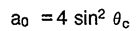
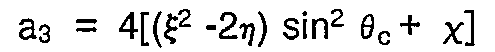
- Assuming that the particles of the incident beam are scattered elastically by a light weight nucleus of mass M₁, and anelastically by a heavy weight nucleus of mass M₂, and Ex as the excitation energy, the relationship between the ϑc angle and the kinetic energy T may be expressed by a fourth degree polynomial:
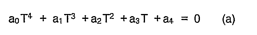
where:


Pr is the moment transferred in correspondence with the crossover and is given by:
Ex being the energy transferred at the crossover and given by

where the masses are expressed in energy units. - The fourth degree polynomial (a) has two actual resolutions: one gives the sought for Ei value, the other the value Er, which is constant with ϑ.
- The accuracy of the determination of the Ei value is solely a function of the precision with which angle ϑc is measured.
- In fact, the imprecision with which Mp, M₁, M₂, Ex are known is pratically negligeable.
- In view of the cited ends, an apparatus was developed for determining the kinetic energy Ei of a ion beam, particularly of light weight ions, characterized by a vacuum scattering chamber and by elaboration means, said chamber consisting of a fixed section and of mobile one, pivotable with respect to the fixed one, the chambers been connected with each other and vacuum proof, wherein the fixed section is operatively connectable with a beam of incident particles and includes a target, consisting of a sheet, a few µm thick, of a suitable material consisting of atoms with light nuclei and atoms with heavy nuclei apt to elastically and anelastically scatter said particles, and wherein the mobile section on its turn comprises means for detecting charged particles and means for transducing the signals supplied by said detector means into electrical signals indicative of the energy possessed by the particles elastically and anelastically scattered by said target, for preselected angular positions of the mobile section with respect to the fixed one, or diffusion angles ϑ, said fixed section being joined to a plate having a preselected graduated scale, said mobile section being fastenable to said plate by micrometric regulation means which regulate its angular position with respect to the fixed section, said elaborating means being programmed for receiving data relating to preselected physical values of said particle beam and data relating to said preselected angular positions of said mobile section with respect to the fixed section and to the relative values of the energy possessed by the elastically scattered particles and of the energy possessed by the anelastically scattered particles by said target, to derive from these data the angular crossover position (crossover angle ϑc) in which the energy of the elastically scattered particle equals the one of the anelastically scattered ones, and, through preselected relativistic kinematics relations, the value of the kinetic energy Ei possessed by the incident particles beam.
- The method according to the invention is characterized in that it comprises the steps of:
- introducing an incident particle beam into a scattering evacuated chamber consisting of a fixed section comprising a target, consisting of a sheet, a few µm thick, of a suitable material consisting of molecules formed by atoms with light weight nuclei and with heavy nuclei, apt to elastically and anelastically scatter said particles, and of a mobile section pivotable with respect to said fixed section, and which can be connected to a plate joined with said fixed section, having a preselected graduated scale, by micrometric regulation means which regulate its angular position with respect to the fixed section, comprising means for detecting charged particles and means for transducing the signals supplied by said detector means into signals indicating the energy possessed by the particles elastically and anelastically scattered by said target,
- directing said particle beam into said scattering chamber to make it incident upon said target;
- detecting the values of the energy possessed by the particles elastically scattered and by the ones anelastically scattered by said target, for pre-established angular inclination positions of said mobile section with respect to the fixed section, or scattering angles ϑ;
- feeding into programmed computers the data relating to preselected physical values of said particle beam and of the data relating to said preselected angular inclination positions and of said detected values of the energy possessed by the particle elastically scattered and by the ones anelastically scattered by said target;
- deriving from said data the angular crossover position (crossover angle ϑc), for which the energy of the elastically scattered particles equals the one of the anelastically scattered ones, and, through preselected relativistic kinematics relationships, the kinetic energy possessed by the incident particles beam.
- Characteristics and advantages of the invention will now be illustrated with reference to figures 1 to 6 enclosed, in which a preferred embodiment of the invention is represented as a non limitative example.
- Fig. 1 is a schematic, partially in section, representation of an apparatus according to the invention;
- Fig. 2 is a view in longitudinal section, in an enlarged scale, of a detail of the apparatus of Fig. 1;
- Fig. 3 is a view in longitudinal section, in an enlarged scale, of another detail of the apparatus of Fig. 1;
- Fig. 4 shows a flow chart of the determination method implemented by the apparatus of Fig. 1;
- Fig. 5 shows a flow chart of a determination method auxiliary to the one of Fig. 4;
- Fig. 6 shows a further flow chart of a determination method auxiliary to the one of Fig. 4.
- Fig. 1 shows in 10 a scattering vacuum chamber according to the invention the chamber consists of a fixed section, indicated as a whole with 11 and of a mobile section, pivotable with respect to the fixed one, indicated as a whole with 12.
- Not shown is the ion beam line, particularly light weight ions, such as protons, deuterons, ³He ions, alpha particles coming from a cyclotron, also not shown, which is joined and coaxial with the fixed section 11.
- Section 11 shows, as can be seen from fig.2 an
aluminum insertion 13, withfins 14, which allow its cooling with air; theinsertion 13 contains acollimator -
Insertion 13 also contains asupport 19 fortarget 20, placing it at the rotation center ofmovable section 12, and abeam suppressor 21, which is electrically, but non thermally, insulated from the rest of the chamber, and which can be connected with a current gauge, not shown, to control the ion beam current incident on the target. -
Target 20 consists of a very thin foil, of a few µm, of a suitable material, such as Mylar, made up of molecules containing hydrogen, carbon and oxygen, or polyethylene, consisting of hydrogen and carbon molecules, that is of light weight nuclei (hydrogen) and heavy nuclei (carbon). - The
number 22 indicates a cylindrical arm of themobile section 12, connected with fixed section 11 andinsertion 13 by means of multilamellar, vacuum tight bellows, 23. Fixed section 11 is joined with asemicircular plate 24, provided with calibratedholes 25, with a 5 degree interaxis, to which correspond calibratedholes 26 on aplate 27 joined withcylindrical arm 22. - The angular excursion of
arm 22 extends from -55° to +55° with respect to the 0° position and its rough positioning with respoect toplate 24 is made by means of plugs (not shown) inserted into calibratedholes - The
number 28 indicates a micrometria regulation device held byspring 29, which allows the precise positioning ofarm 22, within the 5° interval existing between calibratedholes 25. - As shown in fig. 3, inside
shell 30, connected by a flange toarm 22, are located alead shield 31, analuminum collimator 32, acharged particle detector 33, which is supported by acentering ring 34; in the particular case thedetector 33 is of the scintillation type and is coupled withphotomultiplier 35. - The
number 36 indicates a voltage divider, connected tophotomultiplier 35 and to the twovacuum connectors detector 33. -
Connector 38 may be operatively linked throughline 39 to an acquisition system consisting of a pre-amplifier, an amplifier and a multichannel analyser (MCA) schematically represented by 40. - The data supplied by
acquisition system 40 are elaborated by computer programs fed to a programmed computer, as the one indicated by 41, e.g. a personal computer, as it will be further described later. - The beam of light ions, such as protons, deuterons, 3He ions, alpha particles coming from a cyclotron, enters fixed section 11 inciding into
target 20, from which they are scattered, elastically by the light weight hydrogen nuclei and anelastically by the heavy carbon nuclei; the energy possessed by the elestically and by the anelastically scattered ions is detected bydetector 33, for selected angular positions ofmobile section 12 with respect to fixed section 11, or scattering angles ϑ, e.g. some angles to the right and some to the left of position 0°, to correct the unavoidable system asymmetry, and is visualized bysystem analyser 40. Each operation for the acquisition of values takes from a few hundred to about 2000 seconds. - The barycentric E (ϑ) values of peaks in the spectra due to elastic and anelastic scatterings are detected with minimal errors, typically of one or two channels, which correspond to errors of a few tens of keV on the value of the incident beam energy Ei, which is of the order of tens of MeV.
- In
programmed computer 41, which holds the program schematically shown by the flow chart of fig. 4, are introduced as input data: 1) the type of ion incident on the target, in order that the physical values of the incident beam, which are necessary for determining the solutions of the previously cited fourth degree polynomial may be defined; 2) the output data from the analyser ofsystem 40, acquired for selected scattering angles, that is i) the same scattering angles or angular positions ofmobile section 12 with respect to fixed section 11, to the left and to the right of zero; ii) the barycentric values of the peaks of energy E (ϑ) possessed by ions elastically scattered by hydrogen nuclei; iii) the barycentric values of the peaks of energy E (ϑ) possessed by ions anelastically scattered by carbon nuclei; 3) an initial evaluation of the ion beam energy, which can be for example its nominal energy. - In fig. 4, 100 schematizes the initialization; 101 schematizes the introduction of data 1) and 3) cited; 102 the process of detecting the scattering angles to the left of zero; 103 the operations of introduction of data 2) i) ii), respectively 2) i) iii) corresponding to said scattering angles to the left; 104 the operations of determining by interpolation the regression curves representing, as a function of scattering angles ϑ to the left, the course of the energy possessed by the elastically and anelastically scattered ions; 105 the operation of detecting scattering angles ϑ to the right of zero; 106 the introduction of data 2) i) ii) and 2) i) iii) corresponding to said scattering angles to the right; 107 the determination, by interpolationm of regression curves which represent, as a function of scattering angles to the right, the course of the energy possessed by the elastically and anelastically scattered ions; 108 the determination of crossover angles ϑc from regression curves obtained in 104 and in 107; 109 the determination of crossover angle ϑc as an average of the angles obtained in 108; 110 the determination of kinetic energy Ei of the incident ion beam, through resolution of the fourth degree polynomial (a) reported supra; 111 the visualization of results obtained in 109 and 110.
-
Computer 41 may be fed also calculation programs auxiliary to the one schamatically shown in Fig. 4. - For instance, a program for determining the energy of ions scattered at a selected ϑ angle from
target 20, starting from the incident beam energy, so as to allow to single out, through the analyser ofsystem 40, the peaks of spectra relating to the elastic and anelastic scattering of interest. - The flow chart of this program is represented in Fig. 5, in which 120 schematises the inizialization operation, 121 the introduction of data, that is type of ion, incident beam energy, scattering angle; 122 the selection of ion types; 123 the determination of the maximum scattering angle of light weight nuclei (hydrogen); 124 the operation for checking whether the introduced scattering angle is larger than the maximum one; in the affirmative, the scattering energy is made equal zero 125; in the negative, the energy possessed by the elastically scattered ions is determined 126, after having determined the threshold energy for the anelastic scattering, and having checked that the incident ion energy is larger than the threshold one; 127 schematizes the repeated operations for determining the energies of elastically and anelastically scattered ions; 128 the result visualization.
- A further auxiliary calculation program, the flow chart of which is represented in Fig. 6, serves to determine the crossover ϑc angle; after
inizialization 130, andintroduction 131 of input data consisting of ion type, combination of target-nuclei and energy level of the heavy nucleus, and maximum energy of incident ion, the variables Er and Pr are determined of which at equations b) and c), supra, 132 block, and from these thecrossover angle ϑ c 133 block, visualized in 134. - The suggested apparatus and method are particularly interesting because of the reliability and precision of the obtained results and the simplicity and relative rapidity of the operations required.
Claims (12)
- Apparatus for determining the kinetic energy Ei of a particle beam, such as ions, and particularly light weight ions, characterized by a vacuum scattering chamber (10) and computer means (41), said scattering chamber consisting of a fixed section (11) and a mobile section (12) pivotable with respect to the fixed one, the two sections being connected to each other and vacuum proof, wherein the fixed section is operatively connectable to a line of an incident particle beam and comprises a target (20), consisting of a sheet, of a few µm thickness, of a suitable material formed of molecules consisting of atoms with light weight nuclei, and atoms with heavy nuclei, suitable to elastically and anelastically scatter said particles, and wherein the mobile section comprises means (33) for detecting charged particles and means (35,36) for transducing the signals supplied by said detector means into electrical signals indicative of the energy possessed by particles elastically and anelastically scattered by said target for preselected angular positions of the mobile section with respect to the fixed one, or scattering angles ϑ, said fixed setion being joined to a plate (24) provided with a graduated scale, said mobile section being fastenable to said plate by micrometric registration means (28) which regulate its angular position with respect to the fixed section, said computer means (41) being programmed for receiving data relating to selected physical values od said particle beam and data relating to said selected angular positions of said mobile section with respect to the fixed one and to the relative values of the energy possessed by the elastically scattered particles and the energy possessed by the enelastically scattered ones from said target, to derive from said data the crossover angle (ϑc) in which the energy possessed by the elastically scattered particles equals the one possessed by the anelastically scatteres ones, and with the aid of selected relativistic kinematics relationships, the value of the kinetic energy Ei possessed by the incident particles beam.
- Apparatus according to claim 1, characterized in that said fixed section (11) also comprises collimation means (15, 16) for said particle beam, suitable shielding means (17, 19) capable of attenuating the backgroud radiation, supporting means (19), for said target (20) capable of placing it in the rotation centre of said mobile section (12), means for suppressing the beam (21), and said mobile section also comprising respective shielding means (31).
- Apparatus according to claim 1, characterized in that said sections, fixed and mobile (11,12), are connected to each other through multilamellar, vacuum proof bellows (23).
- Apparatus according to claim 1, characterized in that said computer means (41) are programmed to receive as imput data:
1) the type of particles incident on target (20) so that the physical values of the incident beam necessary for determining the solutions of said relativistic kinematics relationships may be defined; 2) the data acquired in said detection operations for the selected diffraction angles, that is i) the same scattering angles or angular positions of said mobile section (12) unit respect to said fixed section (11) on the right and on the left of the zero position; ii) the barycentric values of the peaks of energy E (ϑ) possessed by the particles elastically scattered by the light weight nuclei; iii) the barycentric values of the peaks of energy E (ϑ) possessed by the particles anelastically scattered by the heavy nuclei;
3) an initial evaluation of the value of the energy of the particle beam, which may be, for example, its nominal energy. - Apparatus according to claim 1, characterized in that said target (20) consists of a very thin sheet, a few µm thick, of a suitable material, such as Mylar, or polyethylene.
- Apparatus according to claim 1, characterized in that said computer means (41) are programmed to obtain said kinetic energy value Ei according to the following relationship:

- Method for determining the energy Ei of a ion beam, and particularly of light weight ions, characterized by comprising the steps of:- introducing an incident particle beam into a scattering evacuated chamber (10) consisting of a fixed section (11) comprising a target (20) consisting by a sheet a few µm thick of a suitable material constituted by molecules formed by atoms with light weight nuclei and atoms with heavy nuclei, suitable for the elastical and the anelastical scattering of said particles, and of a mobile section (12) pivotable with respect to said fixed section (11) and which can be joined to a plate (24) joined to said fixed section, provided with a selected graduated scale, with the aid of micrometric registration means (28) which regulate its angular position with respect to said fixed section, comprising means for detecting charged particles (33) and means (35,36) for transducing signals supplied by said detector means into signals indicative of the energy possessed by the particles elastically and anelastically scattered by said target,- directing said particle beam into said scattering chamber to cause their incidence on said target,- detecting the values of the energy possessed by the particles elastically and anelastically scattered by said target, for preestablished inclination angular positions of said mobile section with respect to the fixed section, or scattering angles ϑ,- feeding (101,103,106) into programmed computer means (41) data relative to physical values of said particles beam and data relative to said selected inclination angular positions and said detected values of the energy possessed by the particles elastically scattered and anelastically scattered by said target (20),- deriving from said data (102, 104, 105, 107,108) the angular crossover angle ϑc for which the energy of the elastically scattered particles equals the one of the anelastically scattered particles, and, by means of said selected relativistic kinematics relationships (109, 110), the kinetic energy Ei possessed by the incident particles beam.
- Method according to claim 7, characterized in that said feeding of said programmed computer means (41) consist in introducing as imput data:1) the type of particles incident or target (20), so as to make it possible to define the physical values of the incident beam, needed for determining the solutions of said relativistic kinematic relationships;2) the data acquired in said detection operations for the selected scattering angles, that is i) the same scattering angles or angular positions of said mobile section (12) with respect to said fixed section (11), to the left and to the right of position zero; ii) the barycentric values of the peaks of energy E (ϑ) possessed by the particles elastically scattered by the light weight nuclei; iii) the barycentric values of the peaks of energy E (ϑ) possessed by the particles anelastically scattered by the heavy nuclei; 3) an initial evaluation of the energy value of the particle beam, which may, for example, be its nominal value.
- Method according to claim 7, characterized in that said operations are suitable for obtaining said E₁ kinetic energy value by the following equation:

- Method according to claims 7 to 9, characterized in that it comprises the steps of:- inizializing (100) said computer means (41);- introducing (101) said data 1) and 3);- detecting (102) the scattering angles ϑ to the left of said zero position;- introducing (103) data respectively 2) i) ii) and 2i) iii) corresponding to said scattering angles to the left;- determining (104), by interpolation, the regression curves representing, as a function of the scattering angles to the left, the course of the energy possessed by the elastically and anelastically scattered particles;- detecting (105) the scattering angles ϑ to the left of zero:- introducing (106) data 2)i) ii) and 2)i)iii) corresponding to said scattering angles to the right;- determining (107), by interpolation, of the regression curves representing, as a function of the scattering angles to the right, the course of the energy possessed by the elastically and anelastically scattered particles;- determining (108) the crossover angles ϑc from the regression curves obtained through said operations (104,107);- determining (109) the crossover angle ϑc as an average value of the angles obtained through operations (108);- determining (110) the kinetic energy Ei of the incident particle beam, through the solution of said selected relativistic kinematics relationships;- visualizing (116) the results obtained by means of said 109,110 operations.
- Method according to claim 10, characterized by further comprising the steps of:- a further initializing operation (120)- introducing (121) imput data, that is particle type, incident beam energy, scattering angle ϑ;- selecting (122) a particle type;- determining (123) the maximum scattering angle on light weight nuclei (hydrogen)- cheching (124) whether the introduced scattering angle is larger than the maximum one, and in the affirmative make scattering energy equal zero (125), while in the negative, determine (126) the energy possessed by the elastically scattered particles, after having determined the threshold energy for the anelastic scattering and determined that the incident particle energy is larger than the threshold one;- repeatedly determining (122) the energy of elastically and anelastically scattered particles;- visualizing (128) the results obtained through said (127) operations.
- Method according to claim 10, characterized by comprising also the steps of:- a further initializing operation (130);- introducing (131) imput data consisting of: particle type, combination target nuclei and energy level of heavy nuclei, maximum energy of incident particles;- determining (132) variables Er and Pr of which at the above b) and c) relationships;- determining (133) crossover angle ϑc from the variables obtained through said (132) determination;- visualizing the results (134).
Applications Claiming Priority (2)
| Application Number | Priority Date | Filing Date | Title |
|---|---|---|---|
| IT01998690A IT1246375B (en) | 1990-04-11 | 1990-04-11 | APPARATUS AND METHOD FOR THE ABSOLUTE DETERMINATION OF THE ENERGY OF A BAND OF IONS |
| IT1998690 | 1990-04-11 |
Publications (3)
| Publication Number | Publication Date |
|---|---|
| EP0451802A2 true EP0451802A2 (en) | 1991-10-16 |
| EP0451802A3 EP0451802A3 (en) | 1992-06-03 |
| EP0451802B1 EP0451802B1 (en) | 1996-03-20 |
Family
ID=11162872
Family Applications (1)
| Application Number | Title | Priority Date | Filing Date |
|---|---|---|---|
| EP91105636A Expired - Lifetime EP0451802B1 (en) | 1990-04-11 | 1991-04-10 | Apparatus and method for the absolute determination of the energy of ion beam |
Country Status (6)
| Country | Link |
|---|---|
| US (1) | US5149966A (en) |
| EP (1) | EP0451802B1 (en) |
| AT (1) | ATE135876T1 (en) |
| CA (1) | CA2040207A1 (en) |
| DE (1) | DE69118008T2 (en) |
| IT (1) | IT1246375B (en) |
Families Citing this family (4)
| Publication number | Priority date | Publication date | Assignee | Title |
|---|---|---|---|---|
| JP3143279B2 (en) * | 1993-09-03 | 2001-03-07 | 日本電子株式会社 | Electron energy analyzer |
| US6312925B1 (en) | 1997-05-08 | 2001-11-06 | Epoch Pharmaceuticals, Inc. | Methods and compositions to facilitate D-loop formation by oligonucleotides |
| US10408951B2 (en) * | 2016-01-29 | 2019-09-10 | Board Of Trustees Of Michigan State University | Radiation detector |
| CN112965098A (en) * | 2021-02-04 | 2021-06-15 | 山东省科学院海洋仪器仪表研究所 | Energy calibration method for detecting seawater radionuclide |
Family Cites Families (2)
| Publication number | Priority date | Publication date | Assignee | Title |
|---|---|---|---|---|
| US3920989A (en) * | 1974-09-20 | 1975-11-18 | Minnesota Mining & Mfg | Ion scattering spectrometer utilizing charge exchange processes |
| US4194115A (en) * | 1978-11-07 | 1980-03-18 | Nasa | Method and means for helium/hydrogen ratio measurement by alpha scattering |
-
1990
- 1990-04-11 IT IT01998690A patent/IT1246375B/en active IP Right Grant
-
1991
- 1991-04-10 AT AT91105636T patent/ATE135876T1/en not_active IP Right Cessation
- 1991-04-10 CA CA002040207A patent/CA2040207A1/en not_active Abandoned
- 1991-04-10 US US07/682,963 patent/US5149966A/en not_active Expired - Fee Related
- 1991-04-10 DE DE69118008T patent/DE69118008T2/en not_active Expired - Fee Related
- 1991-04-10 EP EP91105636A patent/EP0451802B1/en not_active Expired - Lifetime
Non-Patent Citations (8)
| Title |
|---|
| INSTRUMENTS AND EXPERIMENTAL TECHNIQUES, vol. 28, no. 3, 1985, NEW YORK, US; pages 659 - 661; TANTSYREV ET AL.: 'ION SOURCE FOR STUDYING ION DISTRIBUTION WITH RESPECT TO INITIAL KINETIC ENERGY' * |
| INSTRUMENTS AND EXPERIMENTAL TECHNIQUES. vol. 28, no. 3, 1985, NEW YORK US pages 659 - 661; TANTSYREV ET AL.: 'ION SOURCE FOR STUDYING ION DISTRIBUTION WITH RESPECT TO INITIAL KINETIC ENERGY' * |
| INSTRUMENTS AND EXPERIMENTAL TECHNIQUES. vol. 30, no. 1, 1987, NEW YORK, US; pages 172 - 175; MEDYNSKII ET AL.: 'ION-KINETIC-ENERGY SPECTROMETER BASED ON MKH-1311 MASS SPECTROMETER' * |
| NUCLEAR INSTRUMENTS & METHODS IN PHYSICS RESEARCH vol. 211, no. 1, June 1983, AMSTERDAM, US; pages 213 - 214; GARIBALDI ET AL.: 'HIGH SPEED ROTATING VACUUM SEAL' * |
| NUCLEAR INSTRUMENTS & METHODS IN PHYSICS RESEARCH, SECTION A, vol. A244, no. 3, April 1986, AMSTERDAM, NL; pages 455 - 476; HAMMER ET AL.: 'SCORPION, THE STUTTGART SCATTERING FACILITY FOR FAST POLARIZED NEUTRONS' * |
| NUCLEAR INSTRUMENTS & METHODS IN PHYSICS RESEARCH, SECTION B, vol. 15, no. 1/6, April 1986, AMSTERDAM, NL; pages 508 - 511; RUDOLPH ET AL.: 'PLASTIC FOILS AS PRIMARY HYDROGEN STANDARDS FOR NUCLEAR REACTION ANALYSIS' * |
| NUCLEAR INSTRUMENTS AND METHODS. vol. 158, no. 1, 1979, AMSTERDAM, NL; pages 185 - 191; SIMON ET AL.: 'A HIGH PRESSURE GAS TERGET SYSTEM FOR THE DETERMINATION OF ABSOLUTE ELECTRON SCATTERING CROSS SECTIONS' * |
| REVIEW OF SCIENTIFIC INSTRUMENTS, vol. 60, no. 10, October 1989, NEW YORK, US; pages 3171 - 3180; POLLARD ET AL.: 'TIME-RESOLVED MASS AND ENERGY ANALYSIS BY POSITION-SENSITIVE TIME -OF-FLIGHT DETECTION' * |
Also Published As
| Publication number | Publication date |
|---|---|
| IT1246375B (en) | 1994-11-18 |
| DE69118008D1 (en) | 1996-04-25 |
| DE69118008T2 (en) | 1996-08-01 |
| EP0451802B1 (en) | 1996-03-20 |
| US5149966A (en) | 1992-09-22 |
| CA2040207A1 (en) | 1991-10-12 |
| IT9019986A0 (en) | 1990-04-11 |
| ATE135876T1 (en) | 1996-04-15 |
| EP0451802A3 (en) | 1992-06-03 |
| IT9019986A1 (en) | 1991-10-11 |
Similar Documents
| Publication | Publication Date | Title |
|---|---|---|
| Rossi | Interpretation of cosmic-ray phenomena | |
| Rajta et al. | Accelerator characterization of the new ion beam facility at MTA Atomki in Debrecen, Hungary | |
| Cleland et al. | A measurement of the β-parameter in the charged nonleptonic decay of the Λ0 hyperon | |
| EP0451802B1 (en) | Apparatus and method for the absolute determination of the energy of ion beam | |
| Fedorov et al. | Measuring the yields and angular distributions of γ quanta from the interaction between 14.1 MeV neutrons and magnesium nuclei | |
| Neuwirth et al. | Energy loss of charged particles in matter: I. Experimental method and velocity dependence of the energy loss of lithium ions | |
| Duxbury et al. | Operational performance characteristics of the WISH detector array on the ISIS spallation neutron source | |
| Vorobyov et al. | Experimental apparatus for the study of small angle neutron-proton elastic scattering at intermediate energies | |
| Bach et al. | Cyclotron Instrumentation for Nuclear Spectroscopy at Medium Resolution in Energy | |
| Miller et al. | Application of fast neutron spectroscopy/radiography to airport security | |
| Rauhala et al. | Stopping powers of Li 7, B 11, C 12, N 14, and O 16 ions in C 16 H 14 O 3 polycarbonate | |
| Parker | The 3H (d, γ) reaction and the 3H (d, γ)/3H (d, n) branching ratio for ec. m.≤ 300 kev | |
| US3934139A (en) | Apparatus for measuring calorific power of hydrocarbon compounds | |
| Mehrhoff et al. | Gamma-ray detection with a 4π NaI spectrometer for material analysis | |
| Kormilitsyn et al. | Application of the LaCl3 (Ce) scintillator to fast neutron measurements | |
| EP0042099A2 (en) | Self-regulating neutron coincidence counter | |
| Barton Jr et al. | The L x-ray spectra from radioactive decay of transuranium elements | |
| Negodaev et al. | Registration of the yield of d+ d nuclear reaction products from a polycrystalline diamond target at the ion accelerator HELIS | |
| Møller et al. | Measurement of the Barkas effect around the stopping-power maximum for light and heavy targets | |
| Brune et al. | Neutron source capabilities at ohio university | |
| US3344273A (en) | Apparatus fos analyzing a gaseous me- dium by subjecting the gas to electron bombardment and measuring the chak- acteristic x-ray emission | |
| Fritscher et al. | Tritium production measurement in a lithium metal sphere with new techniques in neutron source strength determination | |
| Mordovskoy et al. | Setup for Studying the Properties of Highly Excited States of Light Nuclei | |
| Turemen et al. | An Experimental Setup for PIXE Analysis in a Medical Cyclotron at TENMAK-NUKEN | |
| Borst | Proportional counter telescopes for fast neutron spectrometry |
Legal Events
| Date | Code | Title | Description |
|---|---|---|---|
| PUAI | Public reference made under article 153(3) epc to a published international application that has entered the european phase |
Free format text: ORIGINAL CODE: 0009012 |
|
| AK | Designated contracting states |
Kind code of ref document: A2 Designated state(s): AT BE CH DE DK ES FR GB GR IT LI LU NL SE |
|
| RBV | Designated contracting states (corrected) |
Designated state(s): AT BE CH DE DK FR GB LI LU NL SE |
|
| PUAL | Search report despatched |
Free format text: ORIGINAL CODE: 0009013 |
|
| AK | Designated contracting states |
Kind code of ref document: A3 Designated state(s): AT BE CH DE DK ES FR GB GR IT LI LU NL SE |
|
| 17P | Request for examination filed |
Effective date: 19921202 |
|
| 17Q | First examination report despatched |
Effective date: 19950519 |
|
| GRAH | Despatch of communication of intention to grant a patent |
Free format text: ORIGINAL CODE: EPIDOS IGRA |
|
| GRAA | (expected) grant |
Free format text: ORIGINAL CODE: 0009210 |
|
| AK | Designated contracting states |
Kind code of ref document: B1 Designated state(s): AT BE CH DE DK FR GB LI LU NL SE |
|
| PG25 | Lapsed in a contracting state [announced via postgrant information from national office to epo] |
Ref country code: DK Effective date: 19960320 Ref country code: AT Effective date: 19960320 |
|
| REF | Corresponds to: |
Ref document number: 135876 Country of ref document: AT Date of ref document: 19960415 Kind code of ref document: T |
|
| PGFP | Annual fee paid to national office [announced via postgrant information from national office to epo] |
Ref country code: DE Payment date: 19960401 Year of fee payment: 6 |
|
| REG | Reference to a national code |
Ref country code: CH Ref legal event code: NV Representative=s name: BOVARD AG PATENTANWAELTE |
|
| REF | Corresponds to: |
Ref document number: 69118008 Country of ref document: DE Date of ref document: 19960425 |
|
| PG25 | Lapsed in a contracting state [announced via postgrant information from national office to epo] |
Ref country code: LU Free format text: LAPSE BECAUSE OF NON-PAYMENT OF DUE FEES Effective date: 19960430 |
|
| PGFP | Annual fee paid to national office [announced via postgrant information from national office to epo] |
Ref country code: NL Payment date: 19960430 Year of fee payment: 6 Ref country code: FR Payment date: 19960430 Year of fee payment: 6 |
|
| PGFP | Annual fee paid to national office [announced via postgrant information from national office to epo] |
Ref country code: CH Payment date: 19960501 Year of fee payment: 6 |
|
| ET | Fr: translation filed | ||
| PGFP | Annual fee paid to national office [announced via postgrant information from national office to epo] |
Ref country code: BE Payment date: 19960613 Year of fee payment: 6 |
|
| PLBE | No opposition filed within time limit |
Free format text: ORIGINAL CODE: 0009261 |
|
| STAA | Information on the status of an ep patent application or granted ep patent |
Free format text: STATUS: NO OPPOSITION FILED WITHIN TIME LIMIT |
|
| 26N | No opposition filed | ||
| PGFP | Annual fee paid to national office [announced via postgrant information from national office to epo] |
Ref country code: GB Payment date: 19970403 Year of fee payment: 7 |
|
| PG25 | Lapsed in a contracting state [announced via postgrant information from national office to epo] |
Ref country code: SE Effective date: 19970411 |
|
| PGFP | Annual fee paid to national office [announced via postgrant information from national office to epo] |
Ref country code: SE Payment date: 19970416 Year of fee payment: 7 |
|
| PG25 | Lapsed in a contracting state [announced via postgrant information from national office to epo] |
Ref country code: LI Free format text: LAPSE BECAUSE OF NON-PAYMENT OF DUE FEES Effective date: 19970430 Ref country code: CH Free format text: LAPSE BECAUSE OF NON-PAYMENT OF DUE FEES Effective date: 19970430 Ref country code: BE Effective date: 19970430 |
|
| BERE | Be: lapsed |
Owner name: CONSIGLIO NAZIONALE DELLE RICERCHE Effective date: 19970430 |
|
| PG25 | Lapsed in a contracting state [announced via postgrant information from national office to epo] |
Ref country code: NL Effective date: 19971101 |
|
| REG | Reference to a national code |
Ref country code: CH Ref legal event code: PL |
|
| PG25 | Lapsed in a contracting state [announced via postgrant information from national office to epo] |
Ref country code: FR Free format text: LAPSE BECAUSE OF NON-PAYMENT OF DUE FEES Effective date: 19971231 |
|
| PG25 | Lapsed in a contracting state [announced via postgrant information from national office to epo] |
Ref country code: DE Free format text: LAPSE BECAUSE OF NON-PAYMENT OF DUE FEES Effective date: 19980101 |
|
| NLV4 | Nl: lapsed or anulled due to non-payment of the annual fee |
Effective date: 19971101 |
|
| EUG | Se: european patent has lapsed |
Ref document number: 91105636.4 |
|
| REG | Reference to a national code |
Ref country code: FR Ref legal event code: ST |
|
| PG25 | Lapsed in a contracting state [announced via postgrant information from national office to epo] |
Ref country code: GB Free format text: LAPSE BECAUSE OF NON-PAYMENT OF DUE FEES Effective date: 19980410 |
|
| GBPC | Gb: european patent ceased through non-payment of renewal fee |
Effective date: 19980410 |