EP0451710B1 - Powertrain assembly having a T-drive configuration - Google Patents
Powertrain assembly having a T-drive configuration Download PDFInfo
- Publication number
- EP0451710B1 EP0451710B1 EP91105357A EP91105357A EP0451710B1 EP 0451710 B1 EP0451710 B1 EP 0451710B1 EP 91105357 A EP91105357 A EP 91105357A EP 91105357 A EP91105357 A EP 91105357A EP 0451710 B1 EP0451710 B1 EP 0451710B1
- Authority
- EP
- European Patent Office
- Prior art keywords
- gear
- crankshaft
- engine
- drive
- portions
- Prior art date
- Legal status (The legal status is an assumption and is not a legal conclusion. Google has not performed a legal analysis and makes no representation as to the accuracy of the status listed.)
- Expired - Lifetime
Links
Images


Classifications
-
- B—PERFORMING OPERATIONS; TRANSPORTING
- B60—VEHICLES IN GENERAL
- B60K—ARRANGEMENT OR MOUNTING OF PROPULSION UNITS OR OF TRANSMISSIONS IN VEHICLES; ARRANGEMENT OR MOUNTING OF PLURAL DIVERSE PRIME-MOVERS IN VEHICLES; AUXILIARY DRIVES FOR VEHICLES; INSTRUMENTATION OR DASHBOARDS FOR VEHICLES; ARRANGEMENTS IN CONNECTION WITH COOLING, AIR INTAKE, GAS EXHAUST OR FUEL SUPPLY OF PROPULSION UNITS IN VEHICLES
- B60K17/00—Arrangement or mounting of transmissions in vehicles
- B60K17/04—Arrangement or mounting of transmissions in vehicles characterised by arrangement, location, or kind of gearing
- B60K17/06—Arrangement or mounting of transmissions in vehicles characterised by arrangement, location, or kind of gearing of change-speed gearing
-
- B—PERFORMING OPERATIONS; TRANSPORTING
- B60—VEHICLES IN GENERAL
- B60K—ARRANGEMENT OR MOUNTING OF PROPULSION UNITS OR OF TRANSMISSIONS IN VEHICLES; ARRANGEMENT OR MOUNTING OF PLURAL DIVERSE PRIME-MOVERS IN VEHICLES; AUXILIARY DRIVES FOR VEHICLES; INSTRUMENTATION OR DASHBOARDS FOR VEHICLES; ARRANGEMENTS IN CONNECTION WITH COOLING, AIR INTAKE, GAS EXHAUST OR FUEL SUPPLY OF PROPULSION UNITS IN VEHICLES
- B60K17/00—Arrangement or mounting of transmissions in vehicles
- B60K17/34—Arrangement or mounting of transmissions in vehicles for driving both front and rear wheels, e.g. four wheel drive vehicles
-
- B—PERFORMING OPERATIONS; TRANSPORTING
- B60—VEHICLES IN GENERAL
- B60K—ARRANGEMENT OR MOUNTING OF PROPULSION UNITS OR OF TRANSMISSIONS IN VEHICLES; ARRANGEMENT OR MOUNTING OF PLURAL DIVERSE PRIME-MOVERS IN VEHICLES; AUXILIARY DRIVES FOR VEHICLES; INSTRUMENTATION OR DASHBOARDS FOR VEHICLES; ARRANGEMENTS IN CONNECTION WITH COOLING, AIR INTAKE, GAS EXHAUST OR FUEL SUPPLY OF PROPULSION UNITS IN VEHICLES
- B60K5/00—Arrangement or mounting of internal-combustion or jet-propulsion units
- B60K5/04—Arrangement or mounting of internal-combustion or jet-propulsion units with the engine main axis, e.g. crankshaft axis, transversely to the longitudinal centre line of the vehicle
-
- F—MECHANICAL ENGINEERING; LIGHTING; HEATING; WEAPONS; BLASTING
- F02—COMBUSTION ENGINES; HOT-GAS OR COMBUSTION-PRODUCT ENGINE PLANTS
- F02B—INTERNAL-COMBUSTION PISTON ENGINES; COMBUSTION ENGINES IN GENERAL
- F02B75/00—Other engines
- F02B75/16—Engines characterised by number of cylinders, e.g. single-cylinder engines
- F02B75/18—Multi-cylinder engines
- F02B75/20—Multi-cylinder engines with cylinders all in one line
-
- F—MECHANICAL ENGINEERING; LIGHTING; HEATING; WEAPONS; BLASTING
- F16—ENGINEERING ELEMENTS AND UNITS; GENERAL MEASURES FOR PRODUCING AND MAINTAINING EFFECTIVE FUNCTIONING OF MACHINES OR INSTALLATIONS; THERMAL INSULATION IN GENERAL
- F16H—GEARING
- F16H55/00—Elements with teeth or friction surfaces for conveying motion; Worms, pulleys or sheaves for gearing mechanisms
- F16H55/02—Toothed members; Worms
- F16H55/17—Toothed wheels
- F16H55/18—Special devices for taking up backlash
-
- F—MECHANICAL ENGINEERING; LIGHTING; HEATING; WEAPONS; BLASTING
- F02—COMBUSTION ENGINES; HOT-GAS OR COMBUSTION-PRODUCT ENGINE PLANTS
- F02B—INTERNAL-COMBUSTION PISTON ENGINES; COMBUSTION ENGINES IN GENERAL
- F02B75/00—Other engines
- F02B75/16—Engines characterised by number of cylinders, e.g. single-cylinder engines
- F02B75/18—Multi-cylinder engines
- F02B2075/1804—Number of cylinders
- F02B2075/1824—Number of cylinders six
-
- Y—GENERAL TAGGING OF NEW TECHNOLOGICAL DEVELOPMENTS; GENERAL TAGGING OF CROSS-SECTIONAL TECHNOLOGIES SPANNING OVER SEVERAL SECTIONS OF THE IPC; TECHNICAL SUBJECTS COVERED BY FORMER USPC CROSS-REFERENCE ART COLLECTIONS [XRACs] AND DIGESTS
- Y10—TECHNICAL SUBJECTS COVERED BY FORMER USPC
- Y10T—TECHNICAL SUBJECTS COVERED BY FORMER US CLASSIFICATION
- Y10T74/00—Machine element or mechanism
- Y10T74/19—Gearing
- Y10T74/19623—Backlash take-up
Definitions
- the invention relates to automotive vehicle powertrains having an internal combustion engine and multiple ratio gearing arranged in a cross-axis disposition to form a compact assembly.
- the invention is an improvement in the invention disclosed in EP-A-0 439 761 and referring to a T-drive powertrain assembly of the kind as referred to in the preamble of claim 1.
- This earlier European patent application falls within the terms of Article 54(3) of the European Patent Convention, which means that it is not relevant to the question of inventive step.
- the prior T-drive powertrain assembly is adapted particularly to be used in a front-wheel drive vehicle in which the axis of the internal combustion engine is mounted in the direction of the vehicle center plane in a fore-and-aft direction.
- Multiple ratio transmission gearing is arranged with the axis of the gearing disposed perpendicularly with respect to the axis of the engine crankshaft to form a T-drive configuration.
- the vehicle exterior size can be reduced, which results in weight reduction, a reduction in the number of components, and reduced manufacturing cost.
- the prior T-drive configuration is achieved by locating an engine crankshaft gear at a mid-crankshaft position on a nodal point for torsional vibrations in the crankshaft. This divides the crankshaft effectively into two crankshaft portions, each of which has its own natural torsional frequency. The amplitudes of the torsional vibrations that occur in the crankshaft are reduced substantially because of the strategic position of the engine crankshaft gear.
- a T-drive arrangement of such kind is unlike other transaxle arrangements presently used in the automotive industry, such as the transaxle described in US-A-4,509,389 and 4,368,649.
- the engine crankshaft axis is arranged transversely with respect to the vehicle center plane rather than in the fore-and-aft direction, as in the case of the present invention.
- the torque output shaft for the transmission gearing is arranged in spaced, parallel relationship with respect to the crankshaft axis.
- the powertrain assembly provides two crankshaft portions that are arranged end to end.
- Each crankshaft portion has a separate flywheel to absorb engine crankshaft torsional vibrations which affords a correspondingly large axial spacing between the two crankshaft crank portions near the center of the vehicle.
- Such large axial spacing accommodates at the same tine a bevel driving gear between the two crankshaft flywheel masses so that the known assembly accordingly comprises two separate internal combustion engines having their separate crankshaft portions on a common axis.
- the flywheel for one crankshaft portion in each design is between the power take-off gears and that crankshaft portion.
- the other flywheel is similarly disposed between the other crankshaft portion and the power take-off gears.
- the crankshaft gear in the prior powertrain assembly engages a transmission torque input gear.
- the gear teeth for each of the gears are beveled so that the axis of the transmission torque input gear and the crankshaft axis are perpendicular, one with respect to the other.
- One of the possible drawbacks for cross-axis gearing of this kind is the tendency for the cross-axis gears to emanate an undesirable noise because of variations in the tooth geometry for the meshing gear teeth.
- the crankshaft gear itself is subjected to unusual forces because of firing forces of the engine and severe transient torque fluctuations that occur in the direct-driving connection between the crankshaft and the transmission input gearing.
- gear rattle Some of the undesirable gear noise, sometimes referred to as gear rattle, is caused by backlash between meshing gear teeth of the crankshaft gear and the torque input gear for the transmission. Further, the severe forces applied to the gears, because of transient torque fluctuations and engine firing forces tend to reduce the durability of the driving connection between the transmission input gear and the transmission input shaft itself.
- connection between the input shaft and the transmission torque gear input is a spline connection, it is possible that the unusual forces that are transmitted through the gearing will cause failure of the spline teeth. If the driving connection is established by a keyway, it is possible that the unusual forces transmitted through the gearing will destroy the key. In either case, the overall durability of the powertrain is reduced.
- the present invention in accordance with claim 1 overcomes noise problems associated with a cross-axis gearing arrangement for a T-drive of the kind described in preceding paragraphs by eliminating backlash between the torque transmitting gearing, thereby significantly reducing the tendency for the gearing to develop an audible gear noise or gear rattle.
- the present invention furthermore, will improve the durability of the driving connection between the gear and the torque input shaft of the transmission by eliminating the necessity for drive splines or a key and slot connection to establish a torque flow path between the transmission input gear and the input shaft for the multiple ratio transmission.
- Elimination of backlash is accomplished by forming the transmission torque input gear of the cross-axis gearing for the engine crankshaft in two parts, each part having peripheral spiral bevel gear teeth.
- An internal annular recess is formed between the bevel gear sections for accommodating a C-spring that is adapted to establish circumferential torque on the bevel gear portions.
- peripheral teeth on one bevel gear portion cooperate with the bevel gear teeth on the companion bevel gear portion to define a single set of spiral bevel gear teeth adapted to engage the bevel gear teeth on the crankshaft gear.
- Gear assemblies having displaceable gear portions for eliminating backlash are referred to in the industry as scissor gears.
- scissor gears Examples of known scissor gear designs are described in US-A-4,745,823, 3,359,819, and 4,640,147. These patents disclose spur gear teeth wherein the teeth are formed by two gear portions that are subjected to a tangential spring force. The gear portions cooperate to establish a conjugate driving relationship with respect to a drive pinion. The tendency of the spring to establish circumferential displacement of the teeth of the gear portions eliminates backlash at the gear tooth involute faces.
- the transmission torque input bevel gear of the T-drive of the present invention incorporates separate bevel gear portions with a spring means that is particularly adapted to establish opposed torques on the bevel gear parts, which tends to eliminate backlash in the cross-axis gearing.
- the hub of the torque input bevel gear is connected drivably to the input shaft for the multiple ratio gearing without the necessity for using spline teeth or a key-and-slot connection or some similar driving connection that would be susceptible to destruction due to the forces created by the internal combustion engine. This is achieved by providing a hub with a tapered opening on the bevel gear which registers with a tapered section on the torque input shaft for the multiple ratio gearing.
- Internal and external tapered hub surfaces establish a frictional driving connection between the shaft and the bevel gear as the latter is assembled on the shaft with a force fit, thereby eliminating stress points that would be established if a spline connection or a key-and-slot connection or the like were to be used.
- the numeral 10 designates the cylinder block for an internal combustion engine in a front-wheel drive vehicle powertrain package.
- the section plane of Figure 1 is taken along a plane perpendicular to the axis of the crankshaft, the latter being designated by reference character 12.
- a plurality of cylinders 14 is formed in the cylinder block 10.
- Each cylinder has a piston 16 which reciprocates in a cylinder 14.
- a combustion chamber 18 is defined by the upper surface of each piston and the surrounding cylinder head 20.
- cam shaft and valve operators are generally designated by reference character 22. These are located in the upper portion 24 of the cylinder head 20.
- Each piston 16 is connected to the crankshaft bearing portion by a piston rod 26, the end of which carries a bearing cap 28 which surrounds the crank portion 30 of the crankshaft.
- An envelope of crankshaft positions is generally designated by reference character 32.
- the extremities of the lower portion of the connecting rod 26, as the crank portion 30 travels in its circular path, are illustrated in Figure 1 in multiple positions in order to indicate the clearance between the crank end of the connecting rod 26 and the surrounding walls of the engine block 10.
- the engine block has secured to its lower extremity an oil pan 34 which defines a sump 36.
- Pan 34 is bolted to the lower surface 38 of the cylinder block 10.
- crankshaft gear for the cross-axis drive is not illustrated in Figure 1.
- the torque input gear that meshes with the crankshaft gear is shown at 40.
- gear 40 is secured to torque input shaft 42 for the transmission.
- Shaft 42 is journalled at its inboard end 44 on a bearing support 46 which forms a part of the engine block 10.
- the inboard end 48 of the torque input shaft 42 is connected to drive plate 50 for the impeller 52 of a hydrokinetic torque converter 54.
- the impeller 52 comprises a housing 56 which is secured to the outer periphery of the drive plate 50 by bolts 58.
- the impeller housing encloses a bladed turbine 60, which is situated in toroidal fluid flow relationship with respect to the impeller radial outflow passages defined by impeller blades 62.
- a bladed stator 64 is situated in conventional fashion between the flow entrance section of the impeller blades and flow exit section of the turbine 60.
- Stator 64 has a hub 66 mounted on stator sleeve shaft 68, which will be described subsequently with reference to Figure 3.
- An overrunning brake 70 is disposed between the hub 66 of the stator and the stationary sleeve shaft 68.
- the impeller 52 includes a hub 72 which is journalled on the stationary sleeve shaft 68.
- crankshaft is shown in elevation. It includes six cranks, one crank for each of six cylinders.
- the cranks are separately identified by reference characters 74 through 84.
- the engine block 10 has bearing supports, formed integrally with the bearing block, which register with bearing portions on the crankshaft to rotatably support the crankshaft in known fashion.
- the bearing portions on the crankshaft are identified separately by reference characters 86 through 98.
- crankshaft bevel gear 100 Shown in Figure 4 is a crankshaft bevel gear 100, which is carried by a crankshaft bevel gear support 102. It may be secured to the support 102 by welding or by other manufacturing techniques.
- Gear 100 has spiral bevel teeth that mesh with bevel gear teeth formed on bevel gear 40.
- the pitch radius of the bevel gear 40 is such that the centerline of the gear 40 is coincident with the midpoint of the crankshaft, the centerline being designated by reference numeral 104.
- the hub of the impeller shell is piloted at 106 in a pilot opening formed in the outboard end of the input shaft 42.
- Turbine 60 includes a turbine shroud 108 that has a hub 110 splined to turbine shaft 112.
- turbine shaft 112 extends perpendicularly with respect to the axis of halfshaft 114 and companion halfshaft 115 in a front-wheel drive powertrain assembly for a wheeled vehicle.
- the turbine shaft serves as a torque input shaft for a multiple ratio power transmission mechanism. This is schematically illustrated in Figure 2 and identified by reference character 114.
- the torque output shaft for the transmission 114 is connected to drive pinion 116, illustrated in Figure 2 as well as in Figure 3.
- Pinion 116 meshes with differential ring gear 118 of a transaxle differential unit 120.
- Ring gear 118 is carried by differential housing 122, which is journalled by bearing 124 in a right-angle drive housing 126 situated between torque converter housing 128 and the housing for transmission 114. This arrangement also is described in my copending application identified previously.
- Axle shaft 115 is splined to differential side gear 128, and axle shaft 113 is splined to differential halfshaft 130.
- Each side gear meshes with pinions 132 and 134 carried by a pinion shaft that is secured to the housing 122.
- the outboard end of the drive pinion 116 is journalled at 136 in a bearing support that forms a part of the right-angle drive housing 126.
- Axle shafts 113 and 115 are adapted to be connected to axle halfshafts for the front traction wheels of a front-wheel drive vehicle by universal couplings 140 and 142, respectively.
- a positive displacement transmission pump 144 is connected drivably to the impeller hub 72. It is enclosed by pump housing portion 146, which forms a part of the converter housing 128.
- Engine crankshaft torque is delivered to the bevel pinion 40, which drives the impeller.
- Turbine torque developed in the torque converter 54 is transferred through the shaft 112 to torque input elements of the transmission 114.
- the output torque on the output drive gear 116 engages differential ring gear 118, as explained with reference to Figure 3.
- the structure of Figure 2 differs from that of Figure 3, however, because the Figure 2 structure includes a four-wheel drive adaptation. This comprises a secondary ring gear 146, which meshes with bevel pinion 148 drivably connected to driveshaft 150.
- Final drive gears 152 and 154 transfer torque from driveshaft 150 to the rear traction wheels through a suitable U-joint illustrated schematically at 156.
- crankshaft gear 100 and the torque input pinion 40 are subjected to repeated engine firing torque impulses as well as to stresses due to engine crankshaft vibrations. It is necessary, therefore, for the bevel gear teeth of the crankshaft gear and the gear 40 to establish conjugate action with zero backlash. This feature, as well as the hub construction for the gear 40, will be described with reference to Figures 5-8.
- the hub 42 at its outboard end is provided with a tapered section 158, and the cooperating hub portion of the gear 40 has a tapered opening 160, which is adapted to register with tapered portion 158 when the gear 40 is assembled on the hub 42.
- the hub 42 is provided also with a threaded portion 162 on which is threaded a lock nut 164.
- a lock nut 164 When the lock nut 164 is tightened, a force is exerted on the gear 40, thereby establishing a press fit at the cooperating tapered surfaces on the hub and on the gear.
- the frictional connection thus established between the gear 40 and the hub 42 is the only driving connection that is required between the hub 42 and the gear 40. This frictional connection makes it unnecessary to use driving spline teeth or keyways which could be destroyed due to the repeated crankshaft vibrations and firing torques to which the crankshaft gear and the gear 40 are subjected.
- the gear 40 comprises a peripheral portion 166 having formed thereon bevel gear teeth 168. It includes also a secondary peripheral portion 170 on which is formed bevel gear teeth 172. Gear teeth 172 and gear teeth 168 are disposed in aligned relationship to define single continuous gear teeth.
- Bevel gear portion 170 has a pilot hub 174 supported on an annular pilot portion 176 extending toward the engine from the hub 178 of the gear 40. Snap ring 180 maintains the bevel gear portions 172 and 166 in assembled relationship.
- the C-spring is illustrated in Figures 7 and 8.
- Adjacent ends of the C-spring 186 are apertured to receive dowel pins 192 and 194. As seen in Figure 8, these pins extend in opposite directions. As indicated in Figure 5, dowel pins 192 and 194 are received in cooperating openings formed in the bevel gear portions 166 and 170, respectively.
- C-spring 186 is of rectangular cross-section, as indicated in Figure 5.
- the gear teeth 172 and 168 When the gear teeth 172 and 168 are aligned, the C-spring will be stressed, thus providing a continuous torque on the gear portions 166 an 170.
- dowel pin 196 When the gear teeth 172 and 168 are aligned, dowel pin 196 may be inserted through cooperating dowel openings formed in the gear portions 170 and 166, as indicated in Figure 5.
- lock bolts 198 which hold the gear portions 170 and 166 in a fixed position, one with respect to the other when the bevel gear teeth 172 and 168 are machined. Both gear portions 172 and 168 are machined as a single bevel gear in the same machining operation.
- Figure 6 shows the openings 200 and 202 for the dowel pins 194, 192, respectively. They are elongated to facilitate rapid assembly. After the machining operation is complete, the lock bolts 198 are removed. Following assembly, dowel pin 196 is removed, thereby permitting the C-spring to exert a tangential force tending to separate the teeth 172 with respect to the teeth 168 in a tangential direction. This effectively eliminates a backlash condition between the meshing bevel gear teeth of the gear 40 and the bevel gear teeth of the crankshaft gear 100.
- Passage 206 in the shaft 42 extends in an axial direction and communicates with passage 204, the latter extending radially to a location intermediate the axial ends of the hub 178.
- lock nut 164 can be removed and pressurized fluid can be supplied to passage 206, thereby establishing a hydraulic force that separates the hub 178 from the shaft 42.
- FIG. 5 Shown in Figure 5 is the main bearing 208 for supporting the shaft 42.
- the bearing support for the bearing 208 is identified by reference number 210.
- a suitable seal may be used in a seal space shown in Figure 5 at 212 which isolates the interior of the engine crankcase from the interior of the torque converter housing.
Description
- The invention relates to automotive vehicle powertrains having an internal combustion engine and multiple ratio gearing arranged in a cross-axis disposition to form a compact assembly.
- The invention is an improvement in the invention disclosed in EP-A-0 439 761 and referring to a T-drive powertrain assembly of the kind as referred to in the preamble of
claim 1. This earlier European patent application falls within the terms of Article 54(3) of the European Patent Convention, which means that it is not relevant to the question of inventive step. - The prior T-drive powertrain assembly, is adapted particularly to be used in a front-wheel drive vehicle in which the axis of the internal combustion engine is mounted in the direction of the vehicle center plane in a fore-and-aft direction. Multiple ratio transmission gearing is arranged with the axis of the gearing disposed perpendicularly with respect to the axis of the engine crankshaft to form a T-drive configuration. This makes it possible to design the transmission and engine package with minimum space requirements, thereby improving the styling options for the vehicle designer and reducing the intrusion of the engine and transmission assembly into the passenger and cargo space for the vehicle.
- Because of the reduced powertrain dimensions made possible by such a T-drive configuration, the vehicle exterior size can be reduced, which results in weight reduction, a reduction in the number of components, and reduced manufacturing cost.
- The prior T-drive configuration is achieved by locating an engine crankshaft gear at a mid-crankshaft position on a nodal point for torsional vibrations in the crankshaft. This divides the crankshaft effectively into two crankshaft portions, each of which has its own natural torsional frequency. The amplitudes of the torsional vibrations that occur in the crankshaft are reduced substantially because of the strategic position of the engine crankshaft gear.
- The engine dynamic forces that are transmitted to the crankshaft and the loading on the gear that results from the engine firing forces and torques have a minimal effect on the gear tooth loading.
- A T-drive arrangement of such kind is unlike other transaxle arrangements presently used in the automotive industry, such as the transaxle described in US-A-4,509,389 and 4,368,649. In the case of the drivelines described in these prior art references, the engine crankshaft axis is arranged transversely with respect to the vehicle center plane rather than in the fore-and-aft direction, as in the case of the present invention. Further, the torque output shaft for the transmission gearing is arranged in spaced, parallel relationship with respect to the crankshaft axis.
- In the case of the T-drive powertrain assembly described in DE-C-654 326 and related to a rear-wheel drive with the internal combustion engine mounted at a mid-vehicle position, the powertrain assembly provides two crankshaft portions that are arranged end to end. Each crankshaft portion has a separate flywheel to absorb engine crankshaft torsional vibrations which affords a correspondingly large axial spacing between the two crankshaft crank portions near the center of the vehicle. Such large axial spacing accommodates at the same tine a bevel driving gear between the two crankshaft flywheel masses so that the known assembly accordingly comprises two separate internal combustion engines having their separate crankshaft portions on a common axis. The flywheel for one crankshaft portion in each design is between the power take-off gears and that crankshaft portion. The other flywheel is similarly disposed between the other crankshaft portion and the power take-off gears.
- The crankshaft gear in the prior powertrain assembly engages a transmission torque input gear. The gear teeth for each of the gears are beveled so that the axis of the transmission torque input gear and the crankshaft axis are perpendicular, one with respect to the other. One of the possible drawbacks for cross-axis gearing of this kind is the tendency for the cross-axis gears to emanate an undesirable noise because of variations in the tooth geometry for the meshing gear teeth. Furthermore, the crankshaft gear itself is subjected to unusual forces because of firing forces of the engine and severe transient torque fluctuations that occur in the direct-driving connection between the crankshaft and the transmission input gearing. Some of the undesirable gear noise, sometimes referred to as gear rattle, is caused by backlash between meshing gear teeth of the crankshaft gear and the torque input gear for the transmission. Further, the severe forces applied to the gears, because of transient torque fluctuations and engine firing forces tend to reduce the durability of the driving connection between the transmission input gear and the transmission input shaft itself.
- If the connection between the input shaft and the transmission torque gear input is a spline connection, it is possible that the unusual forces that are transmitted through the gearing will cause failure of the spline teeth. If the driving connection is established by a keyway, it is possible that the unusual forces transmitted through the gearing will destroy the key. In either case, the overall durability of the powertrain is reduced.
- The present invention in accordance with
claim 1 overcomes noise problems associated with a cross-axis gearing arrangement for a T-drive of the kind described in preceding paragraphs by eliminating backlash between the torque transmitting gearing, thereby significantly reducing the tendency for the gearing to develop an audible gear noise or gear rattle. The present invention, furthermore, will improve the durability of the driving connection between the gear and the torque input shaft of the transmission by eliminating the necessity for drive splines or a key and slot connection to establish a torque flow path between the transmission input gear and the input shaft for the multiple ratio transmission. - Elimination of backlash is accomplished by forming the transmission torque input gear of the cross-axis gearing for the engine crankshaft in two parts, each part having peripheral spiral bevel gear teeth. An internal annular recess is formed between the bevel gear sections for accommodating a C-spring that is adapted to establish circumferential torque on the bevel gear portions.
- The peripheral teeth on one bevel gear portion cooperate with the bevel gear teeth on the companion bevel gear portion to define a single set of spiral bevel gear teeth adapted to engage the bevel gear teeth on the crankshaft gear.
- Gear assemblies having displaceable gear portions for eliminating backlash are referred to in the industry as scissor gears. Examples of known scissor gear designs are described in US-A-4,745,823, 3,359,819, and 4,640,147. These patents disclose spur gear teeth wherein the teeth are formed by two gear portions that are subjected to a tangential spring force. The gear portions cooperate to establish a conjugate driving relationship with respect to a drive pinion. The tendency of the spring to establish circumferential displacement of the teeth of the gear portions eliminates backlash at the gear tooth involute faces.
- The transmission torque input bevel gear of the T-drive of the present invention incorporates separate bevel gear portions with a spring means that is particularly adapted to establish opposed torques on the bevel gear parts, which tends to eliminate backlash in the cross-axis gearing. The hub of the torque input bevel gear is connected drivably to the input shaft for the multiple ratio gearing without the necessity for using spline teeth or a key-and-slot connection or some similar driving connection that would be susceptible to destruction due to the forces created by the internal combustion engine. This is achieved by providing a hub with a tapered opening on the bevel gear which registers with a tapered section on the torque input shaft for the multiple ratio gearing. Internal and external tapered hub surfaces establish a frictional driving connection between the shaft and the bevel gear as the latter is assembled on the shaft with a force fit, thereby eliminating stress points that would be established if a spline connection or a key-and-slot connection or the like were to be used.
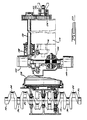
- Figure 1 is an assembly view of a T-drive taken along a plane perpendicular to the axis of the engine crankshaft.
- Figure 2 is a cross-sectional view of the T-drive taken along a plane that contains the engine crankshaft.
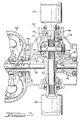
- Figure 3 is a partial cross-sectional assembly view of the T-drive showing a driving connection between the torque output pinion for the multiple ratio gearing and the torque input gear for an output differential unit for front-wheel drive axle half shafts in a front-wheel drive vehicle.
- Figure 4 is an elevation view, partly in cross-section, showing a six cylinder engine crankshaft and a crankshaft gear for the cross-axis gearing.
- Figure 5 is an enlarged cross-sectional subassembly view of the zero backlash gear adapted to be mounted at the torque input side of the multiple ratio gearing.
- Figure 6 is an end view of the structure of Figure 5 as seen from the plane of section line 6-6 of Figure 5.
- Figure 7 is a detailed elevation view of a C-spring for use in the zero backlash gear illustrated in Figure 5.
- Figure 8 is a partial end view of the C-spring of Figure 7 as seen from the plane of section line 8-8 of Figure 7.
- In Figure 1, the
numeral 10 designates the cylinder block for an internal combustion engine in a front-wheel drive vehicle powertrain package. The section plane of Figure 1 is taken along a plane perpendicular to the axis of the crankshaft, the latter being designated byreference character 12. A plurality of cylinders 14 is formed in thecylinder block 10. Each cylinder has a piston 16 which reciprocates in a cylinder 14. Acombustion chamber 18 is defined by the upper surface of each piston and the surroundingcylinder head 20. - The cam shaft and valve operators are generally designated by
reference character 22. These are located in the upper portion 24 of thecylinder head 20. - Each piston 16 is connected to the crankshaft bearing portion by a
piston rod 26, the end of which carries abearing cap 28 which surrounds thecrank portion 30 of the crankshaft. An envelope of crankshaft positions is generally designated byreference character 32. The extremities of the lower portion of the connectingrod 26, as thecrank portion 30 travels in its circular path, are illustrated in Figure 1 in multiple positions in order to indicate the clearance between the crank end of the connectingrod 26 and the surrounding walls of theengine block 10. The engine block has secured to its lower extremity an oil pan 34 which defines a sump 36. - Pan 34 is bolted to the
lower surface 38 of thecylinder block 10. - The crankshaft gear for the cross-axis drive is not illustrated in Figure 1. The torque input gear that meshes with the crankshaft gear is shown at 40. As will be explained subsequently with reference to Figure 5,
gear 40 is secured to torque input shaft 42 for the transmission. Shaft 42 is journalled at its inboard end 44 on abearing support 46 which forms a part of theengine block 10. - The inboard end 48 of the torque input shaft 42 is connected to drive
plate 50 for the impeller 52 of a hydrokinetic torque converter 54. The impeller 52 comprises a housing 56 which is secured to the outer periphery of thedrive plate 50 bybolts 58. - The impeller housing encloses a bladed turbine 60, which is situated in toroidal fluid flow relationship with respect to the impeller radial outflow passages defined by impeller blades 62. A bladed stator 64 is situated in conventional fashion between the flow entrance section of the impeller blades and flow exit section of the turbine 60.
- Stator 64 has a hub 66 mounted on
stator sleeve shaft 68, which will be described subsequently with reference to Figure 3. An overrunning brake 70 is disposed between the hub 66 of the stator and thestationary sleeve shaft 68. - The impeller 52 includes a
hub 72 which is journalled on thestationary sleeve shaft 68. - In Figure 4, the crankshaft is shown in elevation. It includes six cranks, one crank for each of six cylinders. The cranks are separately identified by
reference characters 74 through 84. Theengine block 10 has bearing supports, formed integrally with the bearing block, which register with bearing portions on the crankshaft to rotatably support the crankshaft in known fashion. The bearing portions on the crankshaft are identified separately byreference characters 86 through 98. - Shown in Figure 4 is a
crankshaft bevel gear 100, which is carried by a crankshaftbevel gear support 102. It may be secured to thesupport 102 by welding or by other manufacturing techniques. -
Gear 100 has spiral bevel teeth that mesh with bevel gear teeth formed onbevel gear 40. The pitch radius of thebevel gear 40 is such that the centerline of thegear 40 is coincident with the midpoint of the crankshaft, the centerline being designated byreference numeral 104. - As seen in Figure 1, the hub of the impeller shell is piloted at 106 in a pilot opening formed in the outboard end of the input shaft 42.
- Turbine 60 includes a turbine shroud 108 that has a hub 110 splined to
turbine shaft 112. - As seen in Figure 3,
turbine shaft 112 extends perpendicularly with respect to the axis of halfshaft 114 and companion halfshaft 115 in a front-wheel drive powertrain assembly for a wheeled vehicle. - As explained in my copending patent application previously identified, the turbine shaft serves as a torque input shaft for a multiple ratio power transmission mechanism. This is schematically illustrated in Figure 2 and identified by reference character 114. The torque output shaft for the transmission 114 is connected to drive
pinion 116, illustrated in Figure 2 as well as in Figure 3. -
Pinion 116 meshes withdifferential ring gear 118 of a transaxledifferential unit 120.Ring gear 118 is carried by differential housing 122, which is journalled by bearing 124 in a right-angle drive housing 126 situated betweentorque converter housing 128 and the housing for transmission 114. This arrangement also is described in my copending application identified previously. -
Axle shaft 115 is splined todifferential side gear 128, andaxle shaft 113 is splined todifferential halfshaft 130. Each side gear meshes withpinions 132 and 134 carried by a pinion shaft that is secured to the housing 122. - The outboard end of the
drive pinion 116 is journalled at 136 in a bearing support that forms a part of the right-angle drive housing 126. -
Axle shafts universal couplings - A positive displacement transmission pump 144 is connected drivably to the
impeller hub 72. It is enclosed bypump housing portion 146, which forms a part of theconverter housing 128. - Engine crankshaft torque is delivered to the
bevel pinion 40, which drives the impeller. Turbine torque developed in the torque converter 54 is transferred through theshaft 112 to torque input elements of the transmission 114. In the embodiment of Figure 3, the output torque on theoutput drive gear 116 engagesdifferential ring gear 118, as explained with reference to Figure 3. The structure of Figure 2 differs from that of Figure 3, however, because the Figure 2 structure includes a four-wheel drive adaptation. This comprises asecondary ring gear 146, which meshes withbevel pinion 148 drivably connected todriveshaft 150. Final drive gears 152 and 154 transfer torque fromdriveshaft 150 to the rear traction wheels through a suitable U-joint illustrated schematically at 156. - Except for the rear-wheel drive structure for the Figure 2 embodiment, the embodiments of Figures 3 and 2 are of the same design. Thus, similar reference characters have been applied to indicate elements that are common to both embodiments. The
crankshaft gear 100 and thetorque input pinion 40, as shown in Figure 4, are subjected to repeated engine firing torque impulses as well as to stresses due to engine crankshaft vibrations. It is necessary, therefore, for the bevel gear teeth of the crankshaft gear and thegear 40 to establish conjugate action with zero backlash. This feature, as well as the hub construction for thegear 40, will be described with reference to Figures 5-8. - In Figure 5, it is seen that the hub 42 at its outboard end is provided with a
tapered section 158, and the cooperating hub portion of thegear 40 has a taperedopening 160, which is adapted to register with taperedportion 158 when thegear 40 is assembled on the hub 42. The hub 42 is provided also with a threadedportion 162 on which is threaded alock nut 164. When thelock nut 164 is tightened, a force is exerted on thegear 40, thereby establishing a press fit at the cooperating tapered surfaces on the hub and on the gear. The frictional connection thus established between thegear 40 and the hub 42 is the only driving connection that is required between the hub 42 and thegear 40. This frictional connection makes it unnecessary to use driving spline teeth or keyways which could be destroyed due to the repeated crankshaft vibrations and firing torques to which the crankshaft gear and thegear 40 are subjected. - The
gear 40 comprises aperipheral portion 166 having formed thereon bevel gear teeth 168. It includes also a secondaryperipheral portion 170 on which is formedbevel gear teeth 172.Gear teeth 172 and gear teeth 168 are disposed in aligned relationship to define single continuous gear teeth. -
Bevel gear portion 170 has a pilot hub 174 supported on anannular pilot portion 176 extending toward the engine from thehub 178 of thegear 40.Snap ring 180 maintains thebevel gear portions - The registering surfaces 182 and 184 of the
bevel gear portions spring 186. The C-spring is illustrated in Figures 7 and 8. - Adjacent ends of the C-
spring 186, as shown at 188 and 190, are apertured to receivedowel pins bevel gear portions - C-
spring 186 is of rectangular cross-section, as indicated in Figure 5. When thegear teeth 172 and 168 are aligned, the C-spring will be stressed, thus providing a continuous torque on thegear portions 166 an 170. When thegear teeth 172 and 168 are aligned,dowel pin 196 may be inserted through cooperating dowel openings formed in thegear portions - Shown also in Figure 5 are
lock bolts 198 which hold thegear portions bevel gear teeth 172 and 168 are machined. Bothgear portions 172 and 168 are machined as a single bevel gear in the same machining operation. - Figure 6 shows the
openings lock bolts 198 are removed. Following assembly,dowel pin 196 is removed, thereby permitting the C-spring to exert a tangential force tending to separate theteeth 172 with respect to the teeth 168 in a tangential direction. This effectively eliminates a backlash condition between the meshing bevel gear teeth of thegear 40 and the bevel gear teeth of thecrankshaft gear 100. - To facilitate removal of the
gear hub 178 from the shaft 42 during disassembly, I have provided apressure passage 204.Passage 206 in the shaft 42 extends in an axial direction and communicates withpassage 204, the latter extending radially to a location intermediate the axial ends of thehub 178. To disassemble thehub 178 from shaft 42,lock nut 164 can be removed and pressurized fluid can be supplied topassage 206, thereby establishing a hydraulic force that separates thehub 178 from the shaft 42. - Shown in Figure 5 is the
main bearing 208 for supporting the shaft 42. The bearing support for thebearing 208 is identified by reference number 210. This forms a part of thecylinder housing 10. A suitable seal may be used in a seal space shown in Figure 5 at 212 which isolates the interior of the engine crankcase from the interior of the torque converter housing. Thus, the crankshaft gear and the bevel gear with which it meshes are effectively lubricated with engine oil with no cross-flow of the transmission fluid and engine lubrication oil.
Claims (2)
- A T-drive powertrain assembly for a front-wheel drive vehicle having an internal combustion engine (10) and a multiple ratio transmission (114), said engine and said transmission including a multiple-part housing,
said engine (10) comprising a crankshaft having one crank portion (74, 76, 78, 80, 82, 84) for each cylinder of said engine and bearing portions (86, 88, 90, 92, 94, 96, 98) for mounting the crankshaft with its axis (12) transverse to a for-and-aft geometric center-plane of a vehicle, the vehicle having front traction wheels,
said transmission (114) having a power input shaft (42) providing a gearing axis and being mounted substantially perpendicular to said crankshaft and connected driveably to power input portions of a multiple ratio transmission gearing, a power output shaft (112) driveably connected to power output portions of said gearing and adapted to transfer torque to said front traction wheels,
cross-axis gearing (40, 100) driveably connecting said crankshaft to said power input shaft (42) and comprising a drive gear (100) secured to said crankshaft intermediate its ends and a driven gear (40) engaging said drive gear and being secured to said power input shaft (42), said drive gear (100) and said driven gear (40) having conjugate bevel teeth,
said drive gear (100) being mounted adjacent an axial side of one crank portion (78) and displaced from the midpoint between the axial ends of the crankshaft by such an amount that with respect to the pitch radius of said driven gear (40) the rotation axis (104) of the same intersects the crankshaft axis at a right angle at said midpoint for being coincident therewith;
characterized in thata) said bevel driven gear (40) is mounted on said power input shaft (42) at a position between two axially spaced bearing supports (46, 210) of said multiple-part housing of which the one bearing support (46) is arranged on its engine crankshaft side and the other bearing support (210) is arranged on the opposite side thereof,b) said bevel driven gear (40) has two cooperating bevel gear portions (166, 170) comprising means (182, 184) for piloting and supporting one gear portion for angular movement relative to the other whereby a small degree of relative angular displacement may be accommodated, andc) spring means (186) are provided for applying a torque to said two cooperating bevel gear portions (166, 170) tending to displace angularly one gear portion relative to the other to thereby eliminate backlash. - A T-drive powertrain assembly according to claim 1, wherein said two cooperating bevel gear portions (166, 170) of said bevel driven gear (40) comprise a common gear hub (178) having a tapered opening (160) which is adapted to register with a tapered portion (158) of said power input shaft (42) for establishing a press fit at the cooperating tapered surfaces which is secured by locking means (162, 164).
Applications Claiming Priority (2)
| Application Number | Priority Date | Filing Date | Title |
|---|---|---|---|
| US07/506,144 US5122100A (en) | 1990-04-09 | 1990-04-09 | Powertrain assembly having a t-drive configuration |
| US506144 | 1990-04-09 |
Publications (3)
| Publication Number | Publication Date |
|---|---|
| EP0451710A2 EP0451710A2 (en) | 1991-10-16 |
| EP0451710A3 EP0451710A3 (en) | 1992-07-22 |
| EP0451710B1 true EP0451710B1 (en) | 1996-07-03 |
Family
ID=24013376
Family Applications (1)
| Application Number | Title | Priority Date | Filing Date |
|---|---|---|---|
| EP91105357A Expired - Lifetime EP0451710B1 (en) | 1990-04-09 | 1991-04-04 | Powertrain assembly having a T-drive configuration |
Country Status (4)
| Country | Link |
|---|---|
| US (1) | US5122100A (en) |
| EP (1) | EP0451710B1 (en) |
| JP (1) | JPH04228322A (en) |
| DE (1) | DE69120578T2 (en) |
Families Citing this family (7)
| Publication number | Priority date | Publication date | Assignee | Title |
|---|---|---|---|---|
| US5180346A (en) * | 1991-07-22 | 1993-01-19 | Ford Motor Company | T-drive powertrain assembly for automotive vehicle with forward disposition of the axis for the forward traction wheels |
| US5162025A (en) * | 1991-08-15 | 1992-11-10 | Ford Motor Company | T-drive powertrain assembly |
| GB9721970D0 (en) * | 1997-10-16 | 1997-12-17 | Motor Sport Developments Ltd | Vehicle power transmission |
| FR2867822A1 (en) * | 2004-03-22 | 2005-09-23 | Renault Sas | Clearance compensation elastic ring for backlash pinion, has open ends widened to constitute lugs each of which comprises pin, where pins form rigid assembly with flank and ring is constituted of single part |
| JP5123642B2 (en) * | 2007-10-31 | 2013-01-23 | 本田技研工業株式会社 | Small saddle-ride type vehicle |
| US20090114045A1 (en) * | 2007-11-01 | 2009-05-07 | Brian Wilson | Power Take-Off Unit Having Scissor Gears |
| US9783049B2 (en) * | 2015-10-09 | 2017-10-10 | Ford Global Technologies, Llc | Transmission having power take-off |
Citations (1)
| Publication number | Priority date | Publication date | Assignee | Title |
|---|---|---|---|---|
| US4629354A (en) * | 1985-10-18 | 1986-12-16 | Caterpillar Inc. | Tapered shaft retention apparatus |
Family Cites Families (13)
| Publication number | Priority date | Publication date | Assignee | Title |
|---|---|---|---|---|
| DE654326C (en) * | 1934-03-27 | 1937-12-18 | H C F Porsche G M B H Dr Ing | Multi-cylinder drive motor for motor vehicles with a crankshaft transverse to the longitudinal axis of the vehicle |
| DE762655C (en) * | 1940-07-31 | 1954-12-20 | Ringhoffer Tatra Werke Ag | Arrangement of a transversely mounted engine, especially for rear-engined vehicles |
| US3359819A (en) * | 1966-04-25 | 1967-12-26 | Leo J Veillette | Bidirectional step torque filter with zero backlash characteristic |
| DE1970318U (en) * | 1967-07-27 | 1967-10-12 | Gildemeister Werkzeugmasch | BACKLASH-FREE BEVEL GEAR DRIVE. |
| US4323352A (en) * | 1980-01-14 | 1982-04-06 | William Warren | Cerf cycle |
| US4368649A (en) * | 1980-07-01 | 1983-01-18 | Ford Motor Company | Automatic transaxle driveline having four forward driving ratios and a single reverse ratio |
| GB2092533B (en) * | 1980-12-24 | 1984-12-19 | Fuji Heavy Ind Ltd | Two-four wheel drive mechanism |
| US4456396A (en) * | 1982-01-06 | 1984-06-26 | Elliott Turbomachinery Company, Inc. | Coupling and method of assembly and disassembly |
| JPS611770U (en) * | 1984-06-12 | 1986-01-08 | トヨタ自動車株式会社 | Backless gear device |
| DE3534964A1 (en) * | 1984-10-06 | 1986-04-17 | Zahnradfabrik Friedrichshafen Ag, 7990 Friedrichshafen | ADDITIONAL AXLE DRIVE FOR CONVERTING A SINGLE-AXLE DRIVE IN A MULTI-AXIS DRIVE |
| JPH0141972Y2 (en) * | 1985-06-12 | 1989-12-11 | ||
| US5024287A (en) * | 1987-03-31 | 1991-06-18 | Yamaha Hatsudiki Kabushiki Kaisha | Engine unit for vehicle |
| US4767230A (en) * | 1987-06-25 | 1988-08-30 | Algonquin Co., Inc. | Shaft coupling |
-
1990
- 1990-04-09 US US07/506,144 patent/US5122100A/en not_active Expired - Fee Related
-
1991
- 1991-04-04 EP EP91105357A patent/EP0451710B1/en not_active Expired - Lifetime
- 1991-04-04 DE DE69120578T patent/DE69120578T2/en not_active Expired - Fee Related
- 1991-04-08 JP JP3073440A patent/JPH04228322A/en active Pending
Patent Citations (1)
| Publication number | Priority date | Publication date | Assignee | Title |
|---|---|---|---|---|
| US4629354A (en) * | 1985-10-18 | 1986-12-16 | Caterpillar Inc. | Tapered shaft retention apparatus |
Also Published As
| Publication number | Publication date |
|---|---|
| JPH04228322A (en) | 1992-08-18 |
| EP0451710A3 (en) | 1992-07-22 |
| DE69120578D1 (en) | 1996-08-08 |
| EP0451710A2 (en) | 1991-10-16 |
| DE69120578T2 (en) | 1997-02-27 |
| US5122100A (en) | 1992-06-16 |
Similar Documents
| Publication | Publication Date | Title |
|---|---|---|
| US8221277B2 (en) | Differential provided with a drive wheel | |
| EP1052430B1 (en) | Differential casing | |
| US6146304A (en) | Vehicle differential | |
| GB2121918A (en) | Axially-flexible drive disc | |
| EP0131892B1 (en) | Power transfer device for four wheel drive | |
| US6379277B1 (en) | Limited slip differential mechanism for an automotive vehicle and method for making the same | |
| EP0563895A1 (en) | Differential gear assembly | |
| EP0451710B1 (en) | Powertrain assembly having a T-drive configuration | |
| US5064040A (en) | Splined clutch drum mounting | |
| EP0187750B1 (en) | Countershaft transmission | |
| EP0439761B1 (en) | Powertrain assembly with a cross-axis disposition of the engine crankshaft and the transmission torque input shaft | |
| US6889572B2 (en) | Power-split angular gear | |
| EP1642047A1 (en) | Tamdem axle carrier structural rib | |
| US20010045140A1 (en) | Transmission input shaft | |
| US4614132A (en) | Single centerline cross drive steering transmission | |
| US20190219142A1 (en) | Driveline component having differential assembly with differential gearset configured to limit inboard thrust of side gears | |
| US4899851A (en) | Pressure lubrification device for transmission systems of motor vehicles with transverse gearboxes | |
| US5662544A (en) | Side gear retention of pinion mates | |
| EP0098817B1 (en) | Hub arrangement for a driven vehicle wheel | |
| EP3559490B1 (en) | A joint assembly with an installation aid | |
| JPH09184561A (en) | Differential gear | |
| US4763542A (en) | Side yoke for vehicle differential | |
| JPH07223453A (en) | Quick change type power take-off mechanism with breakaway type collar | |
| EP4108494A1 (en) | Axle assembly having an interaxle differential unit | |
| JPS61192948A (en) | Bevel gear type differential gears |
Legal Events
| Date | Code | Title | Description |
|---|---|---|---|
| PUAI | Public reference made under article 153(3) epc to a published international application that has entered the european phase |
Free format text: ORIGINAL CODE: 0009012 |
|
| AK | Designated contracting states |
Kind code of ref document: A2 Designated state(s): DE FR GB IT |
|
| PUAL | Search report despatched |
Free format text: ORIGINAL CODE: 0009013 |
|
| AK | Designated contracting states |
Kind code of ref document: A3 Designated state(s): DE FR GB IT |
|
| 17P | Request for examination filed |
Effective date: 19921126 |
|
| 17Q | First examination report despatched |
Effective date: 19931126 |
|
| GRAH | Despatch of communication of intention to grant a patent |
Free format text: ORIGINAL CODE: EPIDOS IGRA |
|
| GRAH | Despatch of communication of intention to grant a patent |
Free format text: ORIGINAL CODE: EPIDOS IGRA |
|
| GRAA | (expected) grant |
Free format text: ORIGINAL CODE: 0009210 |
|
| AK | Designated contracting states |
Kind code of ref document: B1 Designated state(s): DE FR GB IT |
|
| REF | Corresponds to: |
Ref document number: 69120578 Country of ref document: DE Date of ref document: 19960808 |
|
| ET | Fr: translation filed | ||
| ITF | It: translation for a ep patent filed |
Owner name: ING. C. GREGORJ S.P.A. |
|
| REG | Reference to a national code |
Ref country code: GB Ref legal event code: 746 Effective date: 19961213 |
|
| PLBE | No opposition filed within time limit |
Free format text: ORIGINAL CODE: 0009261 |
|
| STAA | Information on the status of an ep patent application or granted ep patent |
Free format text: STATUS: NO OPPOSITION FILED WITHIN TIME LIMIT |
|
| 26N | No opposition filed | ||
| REG | Reference to a national code |
Ref country code: FR Ref legal event code: D6 |
|
| PGFP | Annual fee paid to national office [announced via postgrant information from national office to epo] |
Ref country code: GB Payment date: 19990326 Year of fee payment: 9 Ref country code: DE Payment date: 19990326 Year of fee payment: 9 |
|
| PGFP | Annual fee paid to national office [announced via postgrant information from national office to epo] |
Ref country code: FR Payment date: 19990414 Year of fee payment: 9 |
|
| PG25 | Lapsed in a contracting state [announced via postgrant information from national office to epo] |
Ref country code: GB Free format text: LAPSE BECAUSE OF NON-PAYMENT OF DUE FEES Effective date: 20000404 |
|
| REG | Reference to a national code |
Ref country code: FR Ref legal event code: TP Ref country code: FR Ref legal event code: CD |
|
| GBPC | Gb: european patent ceased through non-payment of renewal fee |
Effective date: 20000404 |
|
| PG25 | Lapsed in a contracting state [announced via postgrant information from national office to epo] |
Ref country code: FR Free format text: LAPSE BECAUSE OF NON-PAYMENT OF DUE FEES Effective date: 20001229 |
|
| PG25 | Lapsed in a contracting state [announced via postgrant information from national office to epo] |
Ref country code: DE Free format text: LAPSE BECAUSE OF NON-PAYMENT OF DUE FEES Effective date: 20010201 |
|
| REG | Reference to a national code |
Ref country code: FR Ref legal event code: ST |
|
| PG25 | Lapsed in a contracting state [announced via postgrant information from national office to epo] |
Ref country code: IT Free format text: LAPSE BECAUSE OF NON-PAYMENT OF DUE FEES;WARNING: LAPSES OF ITALIAN PATENTS WITH EFFECTIVE DATE BEFORE 2007 MAY HAVE OCCURRED AT ANY TIME BEFORE 2007. THE CORRECT EFFECTIVE DATE MAY BE DIFFERENT FROM THE ONE RECORDED. Effective date: 20050404 |