EP0451403A1 - Razor mechanism with slidable cartridge support - Google Patents
Razor mechanism with slidable cartridge support Download PDFInfo
- Publication number
- EP0451403A1 EP0451403A1 EP90311663A EP90311663A EP0451403A1 EP 0451403 A1 EP0451403 A1 EP 0451403A1 EP 90311663 A EP90311663 A EP 90311663A EP 90311663 A EP90311663 A EP 90311663A EP 0451403 A1 EP0451403 A1 EP 0451403A1
- Authority
- EP
- European Patent Office
- Prior art keywords
- actuator
- razor mechanism
- cartridge
- mechanism according
- razor
- Prior art date
- Legal status (The legal status is an assumption and is not a legal conclusion. Google has not performed a legal analysis and makes no representation as to the accuracy of the status listed.)
- Granted
Links
Images


Classifications
-
- B—PERFORMING OPERATIONS; TRANSPORTING
- B26—HAND CUTTING TOOLS; CUTTING; SEVERING
- B26B—HAND-HELD CUTTING TOOLS NOT OTHERWISE PROVIDED FOR
- B26B21/00—Razors of the open or knife type; Safety razors or other shaving implements of the planing type; Hair-trimming devices involving a razor-blade; Equipment therefor
- B26B21/40—Details or accessories
- B26B21/52—Handles, e.g. tiltable, flexible
- B26B21/521—Connection details, e.g. connection to razor heads
-
- B—PERFORMING OPERATIONS; TRANSPORTING
- B26—HAND CUTTING TOOLS; CUTTING; SEVERING
- B26B—HAND-HELD CUTTING TOOLS NOT OTHERWISE PROVIDED FOR
- B26B21/00—Razors of the open or knife type; Safety razors or other shaving implements of the planing type; Hair-trimming devices involving a razor-blade; Equipment therefor
- B26B21/08—Razors of the open or knife type; Safety razors or other shaving implements of the planing type; Hair-trimming devices involving a razor-blade; Equipment therefor involving changeable blades
- B26B21/14—Safety razors with one or more blades arranged transversely to the handle
- B26B21/22—Safety razors with one or more blades arranged transversely to the handle involving several blades to be used simultaneously
- B26B21/222—Safety razors with one or more blades arranged transversely to the handle involving several blades to be used simultaneously with the blades moulded into, or attached to, a changeable unit
- B26B21/225—Safety razors with one or more blades arranged transversely to the handle involving several blades to be used simultaneously with the blades moulded into, or attached to, a changeable unit the changeable unit being resiliently mounted on the handle
-
- B—PERFORMING OPERATIONS; TRANSPORTING
- B29—WORKING OF PLASTICS; WORKING OF SUBSTANCES IN A PLASTIC STATE IN GENERAL
- B29C—SHAPING OR JOINING OF PLASTICS; SHAPING OF MATERIAL IN A PLASTIC STATE, NOT OTHERWISE PROVIDED FOR; AFTER-TREATMENT OF THE SHAPED PRODUCTS, e.g. REPAIRING
- B29C65/00—Joining or sealing of preformed parts, e.g. welding of plastics materials; Apparatus therefor
- B29C65/02—Joining or sealing of preformed parts, e.g. welding of plastics materials; Apparatus therefor by heating, with or without pressure
- B29C65/08—Joining or sealing of preformed parts, e.g. welding of plastics materials; Apparatus therefor by heating, with or without pressure using ultrasonic vibrations
-
- B—PERFORMING OPERATIONS; TRANSPORTING
- B29—WORKING OF PLASTICS; WORKING OF SUBSTANCES IN A PLASTIC STATE IN GENERAL
- B29C—SHAPING OR JOINING OF PLASTICS; SHAPING OF MATERIAL IN A PLASTIC STATE, NOT OTHERWISE PROVIDED FOR; AFTER-TREATMENT OF THE SHAPED PRODUCTS, e.g. REPAIRING
- B29C66/00—General aspects of processes or apparatus for joining preformed parts
- B29C66/50—General aspects of joining tubular articles; General aspects of joining long products, i.e. bars or profiled elements; General aspects of joining single elements to tubular articles, hollow articles or bars; General aspects of joining several hollow-preforms to form hollow or tubular articles
- B29C66/51—Joining tubular articles, profiled elements or bars; Joining single elements to tubular articles, hollow articles or bars; Joining several hollow-preforms to form hollow or tubular articles
- B29C66/54—Joining several hollow-preforms, e.g. half-shells, to form hollow articles, e.g. for making balls, containers; Joining several hollow-preforms, e.g. half-cylinders, to form tubular articles
-
- B—PERFORMING OPERATIONS; TRANSPORTING
- B29—WORKING OF PLASTICS; WORKING OF SUBSTANCES IN A PLASTIC STATE IN GENERAL
- B29L—INDEXING SCHEME ASSOCIATED WITH SUBCLASS B29C, RELATING TO PARTICULAR ARTICLES
- B29L2031/00—Other particular articles
- B29L2031/718—Cosmetic equipment, e.g. hair dressing, shaving equipment
- B29L2031/7186—Shaving equipment
Definitions
- the present invention is directed to a razor mechanism and, more particularly, to a razor mechanism with a slidable cartridge support adapted to support a flexible razor cartridge.
- Razor mechanisms are typically designed to securably support a cartridge containing at least one razor blade at the ends and at least one midpoint of the cartridge.
- channel-type razors which typically have two fixed opposing bars adapted to slidably receive a cartridge having a corresponding fixed track.
- Such channel-type razors provide support to a cartridge along the entire longitudinal length of the cartridge.
- An example of a "dynamic" cartridge i.e. a cartridge having a changeable blade geometry having a track for such support is shown in U.S. Patent No. 4,516,320 to Peleckis.
- Another type of razor known in the art includes spring actuated engaging members which, upon the application of force to an actuator button, move inwardly or outwardly. After the cartridge has been properly positioned on the razor handle, the actuator button is released allowing the engaging members to return to their non-biased position and thereby engage the razor cartridge.
- Such razors have been designed to either maintain the razor cartridge fixed with respect to the razor handle or, are of the "pivoting" type, which allow the cartridge to pivot on the razor during shaving.
- An improved razor which allows the cartridge to pivot or to be locked in a non-pivoting manner is disclosed in U.S. Patent No. 4,797,998 which issued to Motta on January 17, 1989 entitled Lockable Pivotable Razor.
- the pivoting cartridge engaging arms disclosed in this Motta patent are releasably locked to provide pivoting support for a cartridge.
- U.S. Patent No. 4,069,580 to Cartwright et al. which reissued as U.S. Patent No. Re. 30,913, discloses a flexible blade cartridge wherein the cartridge is supported on fixed pins of the shaving handle head.
- Another support for a flexible blade cartridge is disclosed in U.S. Patent No. 4,443,939 to Motta et al.
- This new flexible razor head disclosed in U.S. Patent No. 4,854,043 issued on August 8, 1989 which is hereby incorporated by reference, comprises a flexible cartridge which is designed to flex along its longitudinal axis during shaving. It will be appreciated by those skilled in the art that when a flexible cartridge flexs along its longitudinal axis, the linear distance between the ends of the cartridge decreases.
- a razor mechanism wherein the attaching mechanism will securably connect a flexible cartridge to the razor handle while permitting the cartridge to flex during shaving. Since the natural memory of the materials used in forming the flexible cartridge may not be sufficient to return the flexible cartridge to a straight configuration, a preferred razor mechanism would provide a straightening effect. Additionally, it would be especially advantageous to provide a razor mechanism which gives additional support to a flexible cartridge when the cartridge is engaged.
- the present invention provides a razor mechanism, having a central longitudinal axis, for use with a flexible cartridge characterised in that it comprises: means for supporting said flexible cartridge on said razor mechanism said supporting means being moveable in a direction toward said longitudinal axis of said razor mechanism in response to the flexing of said flexible cartridge during shaving; and a cartridge support slidably disposed substantially parallel to said longitudinal axis.
- a preferred embodiment of the present invention provides a razor mechanism having attachment members and a cartridge support which are movable in response to the flexing of a flexible cartridge during shaving.
- the razor mechanism preferably comprises a housing, an actuator, at least one attachment member, and a cartridge support.
- the actuator is slidably connected to the housing and has at least one prong member which engages the attachment member.
- the attachment member is partially disposed within the housing and has an attachment end for engagement with a flexible cartridge in a manner which provides moveable support to the cartridge when the cartridge is flexed during shaving.
- the cartridge support is slidably disposed within the housing and movably engages a center region of the cartridge.
- the cartridge support is advantageously biased in the distal direction to assist the attachment members in returning a deflected razor cartridge to a substantially straight configuration.
- Fig. 1 is a perspective view of the razor mechanism of one embodiment of the present invention.
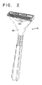
- Fig. 2 is a perspective view of one embodiment of the present invention illustrating the placement of a flexible cartridge thereon.
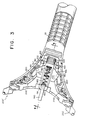
- Fig. 3 is a cross-sectional view of the razor mechanism of Fig. 1 taken along lines 3-3.
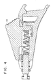
- Fig. 4 is a cross-sectional, side-view of the razor mechanism of the present invention illustrated in Fig. 3 taken along lines 4-4.
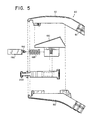
- Fig. 5 is an exploded side-view of the embodiment of the present invention illustrated in Figs. 3 and 4.
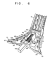
- Fig. 6 is a perspective bottom-view of the top cover assembly of the razor mechanism illustrated in Figs. 3 and 4.
- Fig. 7 is a top-view of the bottom assembly of the embodiment of the present invention illustrated in Figs. 3 and 4.
- Fig. 8 is a top-view of an attachment member of one embodiment of the present invention.
- Fig. 9 is a side-view of the attachment member illustrated in Fig. 8.
- Fig. 10 is a top-view of the distal end of the attachment member illustrated in Fig. 8 taken from the direction of Arrow 9.
- Fig. 11 is an exploded perspective view of the moving elements of the embodiment of the present invention shown in Figs. 3 and 4.
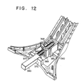
- Fig. 12 is a perspective bottom-view of the top cover assembly of a second embodiment of the razor mechanism of the present invention.
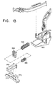
- Fig. 13 is an exploded perspective view of the moving elements of the embodiment of the present invention illustrated in Fig. 12.
- Fig. 14 is an exploded side-view of the embodiment of the present invention illustrated in Figs. 12 and 13.
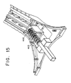
- Fig. 15 is a perspective bottom-view of the top cover assembly of a third embodiment of the razor mechanism of the present invention.
- Fig. 16 is an exploded perspective view of the moving elements of a third embodiment of the present invention illustrated in Fig. 15.
- Fig. 17 is a bottom-view of a portion of a flexible cartridge which may be used with the razor mechanism of the present invention.
- One embodiment of the present invention is a razor mechanism particularly adapted for supporting flexible cartridges and generally comprises a housing, an actuator, at least one attachment member, and a cartridge support wherein the attachment member and cartridge support are movable in response to the flexing of a flexible cartridge during shaving.
- the cartridge support is preferably slidably disposed along the central axis of the razor mechanism. At least a portion of the cartridge support extends outside of the housing for movable engagement with a flexible cartridge.
- the cartridge support is continuously biased outwardly such that the distal end of the cartridge support abuts the bottom of a flexible cartridge, i.e. the side opposite the cap, to assist the flexible cartridge in returning to a substantially linear configuration after flexing.
- the distal movement of the cartridge support is advantageously limited such that the cartridge support does not cause the flexible cartridge to bow outwardly.
- the razor mechanism of the present invention also comprises at least one attachment member for movably supporting a flexible cartridge during shaving.
- the attachment end of the attachment member may move linearly or in an arcuate fashion to provide movable support to the flexible cartridge.
- the attachment member is in sliding communication with a spring-biased actuator which normally urges the attachment end of the attachment member outwardly.
- razor mechanism 10 of one embodiment of the present invention comprises a housing 50, two attachment members 200, 200', an actuator 150 and a cartridge support 190.
- the razor mechanism 10 is adapted to be attached to a handle extension 11.
- Fig. 2 illustrates the positioning of a cartridge on razor mechanism 10.
- housing 50 comprises a top cover 60 and a bottom frame 80.
- Fig. 3 has sections removed to illustrate the cooperative arrangement of the attachment members 200, 200' with the actuator 150 and the positioning of the actuator/support spring 165 and cartridge support 190.
- top cover 60 comprises a gripping portion 61 and a control portion 62.
- Control portion 62 has a central longitudinal axis L best shown in Fig. 7.
- Gripping portion 61 may be designed to have any desirable cross section, for example cylindrical, and is preferably knurled to facilitate gripping by the person shaving.
- Fig. 5 which is an exploded view of this embodiment generally illustrates the relationship between top cover 60, bottom frame 80, center cartridge support 190 and attachment member 200 which are described in further detail below.
- Fig. 6 is a bottom view of the top cover 60 with actuator 150, cartridge support 190 and actuator/support spring 165 assembled thereon.
- control portion 62 of top cover 60 has an exterior side 62a and an interior side 62b.
- Control portion 62 also comprises a window 65 passing through control portion 62 from exterior side 62a to interior side 62b.
- the longitudinal edges of window 65 are substantially parallel to longitudinal axis L.
- Window 65 is adapted to slidably receive actuator 150 and is preferably located in the central region of control portion 62.
- control portion 62 comprises an abutment member 69 which extends downwardly from interior side 62b as shown in Fig. 6 and is preferably disposed adjacent the distal end of window 65.
- abutment member 69 which extends downwardly from interior side 62b as shown in Fig. 6 and is preferably disposed adjacent the distal end of window 65.
- distal refers to the end of an element closest to the end of the razor mechanism which receives the cartridge
- proximal refers to the opposite end, i.e. closest to the handle.
- cartridge support 190 is essentially oblong with a shoulder member 191 and a support pin 192 disposed at the proximal end thereof.
- the shoulder member 191 abuts the proximal side of a central recess 69a of abutment member 69 to limit the movement of the cartridge support 190 in the distal direction.
- the illustrated cartridge support 190 has a generally square cross-section, other symmetric or irregular shapes such as a T-shape could be used.
- Support pin 192 fits within actuator/support spring 165 to prevent slippage between actuator/support spring 165 and the cartridge support 190.
- the spring 165 continuously biases the cartridge support 190 in the distal direction.
- Attachment pins 67 and 68 are provided on interior side 62b for engagement in corresponding receptacles 87 and 88 in the interior side 81b of bottom frame 80 shown in Fig. 7. As shown in Fig. 7, receptacles 87 and 88 are preferably chamfered to aid in the insertion of attachment pins 67 and 68. While the use of pins 67, 68 and corresponding receptacles 87 and 88 is preferred, it will be appreciated by those skilled in the art that top cover 60 and bottom frame 80 may be attached by any suitable method known in the art.
- control portion 62 has a shape which generally flares outwardly from gripping portion 61 and has guide ends 76 and 77 at the distal end of control portion 62 for reasons discussed below.
- the central distal portion 78 of top cover 60 does not extend as far distally as guide ends 76 and 77.
- a lateral guide rail 97 extends downwardly from guide end 77 and extends in a direction generally perpendicular to the longitudinal axis L of razor mechanism 10.
- a similar lateral guide rail 96 extends from guide end 76 and is also positioned substantially perpendicular to the longitudinal axis L of razor mechanism 10.
- gripping portion 61 and control portion 62 may be disposed generally in the same plane, in a preferred embodiment of the present invention as shown in Figs. 5 and 6, gripping portion 61 is disposed at an angle to control portion 62. While the actual angle may vary, it will be appreciated by those skilled in the art that the angle is preferably in the range of about 145 to 160 degrees, and is most preferably about 150 degrees.
- grooved sections 71 and 72 are also adjacent to window 65 on the interior side 62b of top cover 60, shown in Fig. 6.
- the grooved sections 71 and 72 have outer edges which extend generally parallel to the longitudinal edges of window 65. These grooved sections 71 and 72 receive actuator shoulders 156,157 as the actuator 150 is moved within window 65.
- Interior portion 62b of top cover 60 has two recesses 301, 302 (not shown) disposed adjacent window 65 and proximally of the grooved sections 71, 72, respectively.
- An actuator 150 illustrated in Figs. 5 and 11, is slidably disposed in window 65 of top cover 60.
- Actuator 150 comprises an upper gripping portion 152 having a width slightly less than the width of window 65 and a length slightly greater than the length of window 65.
- Upper gripping surface 152 may advantageously comprise raised protrusions in order to facilitate gripping of actuator 150 by a person desiring to position a cartridge on razor mechanism 10.
- actuator 150 also has shoulders 156 and 157 which are disposed below and to either side of upper gripping portion 152.
- the shoulders 156 and 157 extend outwardly such that the distance between the ends of shoulders 156 and 157 is greater than the width of window 65.
- shoulders 156 and 157 are designed to slidingly fit within grooves 71 and 72 of control portion 62.
- Actuator 150 also comprises prong members 180 and 181 which extend downwardly from shoulders 156 and 157 of actuator 150.
- prong members 180 and 181 are positioned at the ends of shoulders 156 and 157 respectively, however, it will be appreciated that alternate positioning is possible within the scope of the present invention.
- Actuator 150 also has an actuator pin 161 best shown in Fig. 4, mounted on a support member 162 disposed below upper gripping surface 152 and toward the proximal end of actuator 150.
- Actuator pin 161 is designed to engage the proximal end of an actuator/support spring 165.
- the distal end of actuator/support spring 165 engages support pin 192 and thereby biases actuator 150 toward the proximal end of control portion 62.
- three sides of actuator pin 161 may be substantially surrounded by support member 162 and pin walls 166 and 167 in order to prevent other moving elements of the razor mechanism 10 from interfering with the action of actuator/support spring 165.
- Fig. 11 is an exploded view showing the cooperative arrangement of abutment member 69, cartridge support 190, actuator/support spring 165, actuator 150, and attachment members 200, 200'.
- actuator 150, cartridge support 190 and spring 165 are designed for easy assembly with top cover 60.
- the cartridge support 190 is placed within recess 69a of abutment member 69.
- the spring 165 is placed over the actuator pin 161 and, while the cartridge support 190 is held in place, gripping portion 152 of actuator 150 is inserted, distal end first, upwardly through window 65 of control portion 62 and the distal end of spring 165 is placed over support pin 192. It will be appreciated that shoulders 156 and 157 prevent actuator 150 from passing entirely through window 65.
- the actuator When the distal end of gripping portion 152 has passed through window 65, the actuator is slid distally compressing spring 165, and then actuator 150 is rotated so that the proximal end of gripping portion 152 passes through window 65. When the actuator 150 is released, spring 165, which is then in contact with support pin 192, urges actuator 150 proximally in window 65.
- the distance between the distal end of the actuator shoulders 156, 157 and the proximal end of the gripping portion 152 is less than the longitudinal length of window 65.
- the longitudinal length of gripping member 152 is greater than the longitudinal length of window 65, therefore, unless actuator 150 is rotated relative to control portion 62, actuator 150 will not fall downwardly through window 65 after it has been installed.
- a spring 165 may be placed upon pin actuator 161 and actuator 150 can then be easily positioned within control portion 62 of top cover 60.
- the spring 165 simultaneously serves the three purposes of biasing actuator 150 toward the proximal end of control portion 62, maintaining actuator 150 within the control portion 62 during normal operation of the razor mechanism 10, and biasing cartridge support 190 distally to maintain contact with a flexible cartridge.
- bottom frame 80 similarly has a control portion 81 and a stem portion 82.
- Control portion 81 has an exterior side 81a and an interior side 81b.
- Bottom frame 80 is shaped to correspond to top cover 60 such that control portion 81 also generally flares outwardly from stem portion 82.
- the distal end of control portion 81 has two guide ends 83, 84 and two lateral guide rail 85, 86 which, upon assembly of the housing 50, are aligned, but are not in contact with the two lateral guide rail 96, 97 of the top cover 60.
- the lateral guide rail 85, 86 of bottom frame 80 are disposed generally perpendicular to the longitudinal axis L of razor mechanism 10.
- the interior side 81b of bottom frame 80 also has two recesses 101, 102, (shown best in Fig. 3) which are preferably circular, in order to pivotally receive protrusions of attachment member 200 in a manner described below.
- Interior side 81b also has receptacles 87, 88 which receive the attachment pins 67, 68 of top cover 60.
- receptacles 87 and 88 are preferably chamfered in order to facilitate the aligning of the pins 67, 68 within the receptacles 87, 88.
- the attachment pins 67, 68 of top cover 60 are securably locked within the receptacles 87, 88 of the bottom frame 80 by any suitable method known in the art, such as by ultrasonic welding.
- the central, distal portion 100 of bottom frame 80 does not extend as far distally as the guide ends 83, 84.
- Disposed between the center of distal portion 100 and the guide ends 83, 84 are lower end plates 89, 90 which extend upwardly from the interior side 81b of bottom frame 80.
- the lower end plates 89, 90 in cooperation with abutment member 69, substantially seal the distal end of housing 50 to prevent soap, hair and other debris from entering the interior of housing 50 and interfering with the movement of pieces located therein.
- top cover 60 and bottom frame 80 are preferably in contact to prevent debris from entering the interior of housing 50 from other sides as well.
- interior guide surfaces 103 and 104 are advantageously disposed adjacent to receptacles 87 and 88, near the exterior edges of bottom frame 80 on interior side 81b.
- stops 105, 105' Disposed toward the distal ends of the interior guide surfaces 103, 104 and spaced proximally from the lateral guide rails 85, 86 are two stops 105, 105' which protrude upwardly from interior surface 81b.
- the stops 105, 105' limit the outward movement of the two attachment members 200, 200'. The inward movement is limited by the outer edges 89', 90' of the two lower end plates 89,90.
- Bottom frame 80 also comprises generally rectangular slots 99, 99' which are spaced by a distance slightly greater than the width of support member 162. Rectangular slots 99, 99' receive the lower end of actuator 150 defined by pin walls 166 and 167 in order to provide further guidance and support to the sliding movement of actuator 150 within housing 50.
- the attachment member 200 of one embodiment of the present invention comprises a proximal end 201 and a distal end 202.
- proximal end 201 has protrusions 210 and 211 which are adapted to pivotally connect attachment member 200 to the recesses 301 and 101 in top cover 60 and bottom frame 80, respectively. It will be appreciated by those skilled in the art that other mechanical arrangements may be utilized in pivotally attaching the proximal end 201 of attachment member 200 within housing 50.
- Attachment member 200 also comprises an actuator receptor 220 which receives a prong member 180 of actuator 150.
- the actuator receptor 220 is disposed at an acute angle to the longitudinal axis L of razor mechanism 10.
- the acute angle which is defined by a central line passing down the center of actuator receptor 220 and the longitudinal axis L of housing 50, is preferably between about 20 and 45 degrees when the attachment member 200 is in a relaxed position i.e. when attachment member 200 is not subject to outside forces such as those exerted by the actuator 150 or by a flexed cartridge at distal end 202.
- actuator 150 When attachment member 200 is in this "relaxed" position, prong 180 of actuator 150 is disposed at the proximal end of actuator receptor 220. While actuator receptor 220 preferably has chamfered rails 221, 222 on both sides and preferably passes entirely through attachment member 200, it will be appreciated by those skilled in the art that similarly positioned grooves which do not pass entirely through attachment member 200 may be utilized.
- attachment member 200 has lateral guide grooves 230 and 231, spaced slightly from distal end 202 of attachment member 200 which are designed to receive lateral guide rails 96 and 86 of housing top cover 60 and bottom frame 80, respectively.
- Lateral guide groove 230 has opposing generally parallel surfaces 232 and 233 which generally abut the lateral guide rail 96 of top cover 60.
- lateral guide rails 85, 86, 96 and 97 are all disposed substantially perpendicular to the longitudinal axis L of razor mechanism 10. Therefore, the engagement of the lateral guide rails within the lateral guide grooves of the attachment members 200, 200' maintains the relative motion of the distal ends of attachment members 200 and 200' substantially perpendicular to the longitudinal axis of razor mechanism 10.
- Inner stop surface 235 and outer stop surface 236 Disposed at the inner and outer edges of lateral guide groove 230 are inner stop surface 235 and outer stop surface 236.
- Outer stop surface 236 is aligned to contact stop 105' and thereby limits the outward movement of attachment member 200 when attachment member 200 is in a "relaxed" position.
- Inner stop surface 235 is aligned to contact lower end plate 90 which thereby limits the inward movement of attachment member 200 when an inwardly directed force is exerted on attachment member 200.
- attachment member 200 is pivotally attached to housing 50 at proximal end 201, it will be appreciated by those skilled in the art that if attachment member 200 was not sufficiently flexible in the region between actuator receptor 220 and distal end 202, the distal end 202 of pivot member 200 would tend to rotate around the recesses 101, 301 instead of moving perpendicular to the longitudinal axis L of razor mechanism 10 as desired in this embodiment. For this reason, attachment member 200 is provided with flexure points 239 and 240 between actuator receptor 220 and lateral guide grooves 230, 231. Flexure points 239 and 240 are preferably simply formed by using a resilient material, e.g. an acetal copolymer, when forming attachment member 200, and by keeping the thickness of attachment member 200 at these additional flexure points 239 and 240 within limits which allow the flexing but prevent breakage of the attachment member 200.
- a resilient material e.g. an acetal copolymer
- Distal end 202 of attachment member 200 has protrusion members 250 and 251 mounted on neck 255.
- neck 255 may be advantageously tapered having a narrower end 256 immediately adjacent the protrusion members 250, 251 and gradually get wider toward the proximal end of pivot member 200 until reaching shoulders 257 and 258. The advantages provided by this tapered configuration are discussed below.
- the attachment members 200, 200' are arranged such that the proximal ends 201, 201' are pivotally connected to the interior of housing 50, the actuator receptors 220, 220' receive prong members 180, 181, the lateral guide grooves are slidingly engaged by the lateral guide rails disposed at the distal ends of housing 50, and the distal ends 202, 202' of the attachment members are disposed outside of housing 50.
- the attachment ends of attachment members are guided in a direction substantially perpendicular to longitudinal axis L in response to forces applied by a flexing cartridge or by actuator 150.
- actuator 150 When actuator 150 is slid toward the distal end of housing 50, the two prong members 180, 181 engage the inner edges of two corresponding actuator receptors 220, 220'. Since the prong members 180, 181 move parallel to the longitudinal axis L of the razor handle mechanism 10, it will be appreciated from the above description and Figures that the distal end 223 of actuator receptor 220 is pulled toward the center of the razor mechanism 10. Movement of actuator receptor 220, therefore, causes the lateral movement of distal end 202 of attachment member 200 which, due to the cooperation of lateral guide grooves 230, 231 within lateral guide rails 301, 101, is substantially perpendicular to the longitudinal axis L of razor mechanism 10.
- actuator/support spring 165 urges the actuator in the proximal direction.
- the two prong members 180,181 engage the outer edges of the corresponding actuator receptors 220,220' as the actuator 150 urges the attachment members 200,200' away from the center of the razor mechanism 10.
- the operation of the attachment member 200 within housing 50 is similar to a conventional 4-bar linkage mechanism.
- the 4-bars are generally defined by: 1) the lower portion of the attachment member extending from proximal end 201 to first flexure point 239; 2) the extension of attachment member 200 between the first flexure point 239 and the second flexure point 240; 3) the portion of attachment member 200 disposed between second flexure point 240 and lateral guide groove 230, and 4) the portion of housing 50 between the recesses 101 and 301 which receive protrusions 210 and 211 at the proximal end of attachment member 200 and the lateral guide rails 96 and 86 which cooperate with lateral guide grooves 230 and 231 of attachment member 200.
- a support spring 365 extends into a bore 392 in the proximal end of cartridge support 390 and abuts the distal end of a stationary abutment member 369.
- An actuator spring 366 is disposed between the proximal side of the abutment member 369 and actuator pin 361. As illustrated, the abutment member 369 is spaced from the distal end of top cover 360. In this manner, cartridge support 390 is continuously biased distally to a point limited by distal abutment member 370, and actuator 350 is biased in the proximal direction.
- tandem spring design of this embodiment of the present invention operates in a fashion similar to the embodiment described above.
- the two spring design permits the application of different forces on the cartridge support and actuator, respectively.
- a third embodiment of the present invention which also utilizes two separate springs for biasing a cartridge support and an actuator.
- a support spring 465 is disposed in overlapping and concentric arrangement with an actuator spring 466.
- Support spring 465 engages both the actuator pin 461 and the slidable cartridge support 496.
- Actuator spring 466 engages the support member 462 of actuator 450 and the proximal side of abutment member 469.
- This embodiment has the advantage of providing the ability to independently control the forces maintained on the actuator and cartridge support while reducing the space within the razor mechanism which is used by the biasing elements. Since it is often desirable to minimize the size of a razor mechanism for aesthetic and other purposes, the embodiment of Figs. 15 and 16 can be particularly desirable.
- the cartridge 600 has an attachment slot 610 defined by outer sidewalls 615 and 620, inner wall 635, outer wall 640, and two slot cover plates 650, 660 having inner edges 651, 661, respectively.
- Inner wall 635 has an inner wall slot 680 defined by inner side walls 625, 630.
- the slot cover plates 650, 660 cover the outer ends of the slot 610 but, as shown in Fig. 17, leave a portion of the inner end of slot 610 and the entire central region of slot 610 uncovered for the passage of neck 255 of attachment member 200.
- the actuator 150 is moved distally causing distal ends 202, 202' to move "inwardly", i.e. toward the center of razor mechanism 10.
- the protrusions members 250, 251 are inserted into the inner end of slot 610 and then, upon release of actuator 150, are biased outwardly to the end of slot 610 covered by the slot cover plates 650, 660.
- At least one of the attachment members of the present invention must be movable, however, it is not required that the movement be in a direction perpendicular to the longitudinal axis L.
- a pair of movable rigid attachment members may be provided by simply forming the attachment members described above with a rigid material and eliminating the reduced thickness flexure points.
- the rigid attachment members could be similarly engaged with a spring-biased actuator, identical to actuator 150 described above, for biasing the rigid attachment members outward, i.e. away from the longitudinal axis of the razor mechanism. Since the attachment ends of such attachment members would move in an arcuate path, the guide grooves would have to be modified slightly. However, since each attachment end moves only a short distance, the short arcuate path approximates a straight line and adequately supports a flexible cartridge.
- rigid attachment members may be slidably disposed in lateral grooves for movement in the direction perpendicular to the longitudinal axis of the razor.
- the rigid attachment members could be urged outwardly, i.e. away from the central longitudinal axis, by a laterally disposed spring.
- the present invention advantageously utilizes the combined forces of a center cartridge support and at least one outwardly biased attachment member, to return a flexible cartridge to a substantially straight configuration.
- the center cartridge support is preferably freely slidable in order to constantly maintain a distally-directed force on a bent flexible cartridge.
- the term "flexible” includes shaving blade assemblies in which the amount of flexing thereof in response to normal human shaving forces is sufficient to substantially conform the blade assembly to many of the non-planar surfaces shaved, and to exclude the relatively rigid prior art shaving blade assemblies which in response to those same shaving forces do not flex or yield more than an insignificant amount insofar as contour-following characteristics are concerned.
- a typical razor cartridge is on the order of about 1.6 inches long.
- the present invention is designed to support flexible razor cartridges which may be deflected up to about 0.20 inches and preferably about 0.120 inches at their midpoints. It will be appreciated that this deflection is measured as the distance between the midpoint of the razor cartridge when the razor cartridge is in a "relaxed", generally straight configuration and when the cartridge is flexed as much as the razor mechanism of the present invention will permit during shaving.
- the attachment members of the present invention are designed to each move a maximum distance of about 0.040 inches, and preferably to move a distance of about 0.015 inches.
- the attachment members preferably move about 0.015 inches when the midpoint of the flexible cartridge is deflected about 0.120 inches.
- the attachment members preferably move about 0.050 inches in response to forces between about 60 and 150 grams and most preferably about 120 grams.
Abstract
Description
- The present invention is directed to a razor mechanism and, more particularly, to a razor mechanism with a slidable cartridge support adapted to support a flexible razor cartridge.
- Many types of razor mechanisms are known in the art. Razor mechanisms are typically designed to securably support a cartridge containing at least one razor blade at the ends and at least one midpoint of the cartridge.
- Among the various types of razor mechanisms known in the art are the channel-type razors which typically have two fixed opposing bars adapted to slidably receive a cartridge having a corresponding fixed track. Such channel-type razors provide support to a cartridge along the entire longitudinal length of the cartridge. An example of a "dynamic" cartridge, i.e. a cartridge having a changeable blade geometry having a track for such support is shown in U.S. Patent No. 4,516,320 to Peleckis.
- Another type of razor known in the art includes spring actuated engaging members which, upon the application of force to an actuator button, move inwardly or outwardly. After the cartridge has been properly positioned on the razor handle, the actuator button is released allowing the engaging members to return to their non-biased position and thereby engage the razor cartridge. Such razors have been designed to either maintain the razor cartridge fixed with respect to the razor handle or, are of the "pivoting" type, which allow the cartridge to pivot on the razor during shaving. An improved razor which allows the cartridge to pivot or to be locked in a non-pivoting manner is disclosed in U.S. Patent No. 4,797,998 which issued to Motta on January 17, 1989 entitled Lockable Pivotable Razor. The pivoting cartridge engaging arms disclosed in this Motta patent are releasably locked to provide pivoting support for a cartridge.
- The attaching mechanisms of the razors known in the prior art have generally been designed to remain in fixed lateral positions while the razor is in use. For example, U.S. Patent No. 4,069,580 to Cartwright et al., which reissued as U.S. Patent No. Re. 30,913, discloses a flexible blade cartridge wherein the cartridge is supported on fixed pins of the shaving handle head. Another support for a flexible blade cartridge is disclosed in U.S. Patent No. 4,443,939 to Motta et al.
- In order to provide a closer shave, a new type of flexible razor cartridge has recently been developed. This new flexible razor head, disclosed in U.S. Patent No. 4,854,043 issued on August 8, 1989 which is hereby incorporated by reference, comprises a flexible cartridge which is designed to flex along its longitudinal axis during shaving. It will be appreciated by those skilled in the art that when a flexible cartridge flexs along its longitudinal axis, the linear distance between the ends of the cartridge decreases. Since the attachment mechanisms of razors known in the art have been conventionally designed to remain in fixed positions except when the cartridge is being attached or detached from the razor, such conventional handles would either not permit the desired flexing of the flexible-type cartridges or, if such flexing was permitted, would create the risk that the cartridge becomes dislodged from the razor mechanism. Pending U.S. patent application Serial No. 07/361,454 filed on June 5, 1989 entitled "Razor Mechanism", which is hereby incorporated by reference, discloses alternatives to conventional designs. The alternatives have attachment members which provide moving support to a flexible cartridge which flexes during shaving.
- Additionally, some razor mechanisms known in the art for flexible cartridges require the flexing of the razor cartridges when the cartridge is being attached to the razor mechanism. It would be very desirable to eliminate the danger inherent in the manual flexing of a flexible cartridge which could slip and injure the user.
- In light of the relatively new flexible-type cartridge design, it is also desirable to provide a razor mechanism wherein the attaching mechanism will securably connect a flexible cartridge to the razor handle while permitting the cartridge to flex during shaving. Since the natural memory of the materials used in forming the flexible cartridge may not be sufficient to return the flexible cartridge to a straight configuration, a preferred razor mechanism would provide a straightening effect. Additionally, it would be especially advantageous to provide a razor mechanism which gives additional support to a flexible cartridge when the cartridge is engaged.
- The present invention provides a razor mechanism, having a central longitudinal axis, for use with a flexible cartridge characterised in that it comprises:
means for supporting said flexible cartridge on said razor mechanism
said supporting means being moveable in a direction toward said longitudinal axis of said razor mechanism in response to the flexing of said flexible cartridge during shaving; and
a cartridge support slidably disposed substantially parallel to said longitudinal axis. - A preferred embodiment of the present invention provides a razor mechanism having attachment members and a cartridge support which are movable in response to the flexing of a flexible cartridge during shaving. The razor mechanism preferably comprises a housing, an actuator, at least one attachment member, and a cartridge support. The actuator is slidably connected to the housing and has at least one prong member which engages the attachment member. The attachment member is partially disposed within the housing and has an attachment end for engagement with a flexible cartridge in a manner which provides moveable support to the cartridge when the cartridge is flexed during shaving. The cartridge support is slidably disposed within the housing and movably engages a center region of the cartridge. The cartridge support is advantageously biased in the distal direction to assist the attachment members in returning a deflected razor cartridge to a substantially straight configuration.
- Fig. 1 is a perspective view of the razor mechanism of one embodiment of the present invention.
- Fig. 2 is a perspective view of one embodiment of the present invention illustrating the placement of a flexible cartridge thereon.
- Fig. 3 is a cross-sectional view of the razor mechanism of Fig. 1 taken along lines 3-3.
- Fig. 4 is a cross-sectional, side-view of the razor mechanism of the present invention illustrated in Fig. 3 taken along lines 4-4.
- Fig. 5 is an exploded side-view of the embodiment of the present invention illustrated in Figs. 3 and 4.
- Fig. 6 is a perspective bottom-view of the top cover assembly of the razor mechanism illustrated in Figs. 3 and 4.
- Fig. 7 is a top-view of the bottom assembly of the embodiment of the present invention illustrated in Figs. 3 and 4.
- Fig. 8 is a top-view of an attachment member of one embodiment of the present invention.
- Fig. 9 is a side-view of the attachment member illustrated in Fig. 8.
- Fig. 10 is a top-view of the distal end of the attachment member illustrated in Fig. 8 taken from the direction of Arrow 9.
- Fig. 11 is an exploded perspective view of the moving elements of the embodiment of the present invention shown in Figs. 3 and 4.
- Fig. 12 is a perspective bottom-view of the top cover assembly of a second embodiment of the razor mechanism of the present invention.
- Fig. 13 is an exploded perspective view of the moving elements of the embodiment of the present invention illustrated in Fig. 12.
- Fig. 14 is an exploded side-view of the embodiment of the present invention illustrated in Figs. 12 and 13.
- Fig. 15 is a perspective bottom-view of the top cover assembly of a third embodiment of the razor mechanism of the present invention.
- Fig. 16 is an exploded perspective view of the moving elements of a third embodiment of the present invention illustrated in Fig. 15.
- Fig. 17 is a bottom-view of a portion of a flexible cartridge which may be used with the razor mechanism of the present invention.
- One embodiment of the present invention is a razor mechanism particularly adapted for supporting flexible cartridges and generally comprises a housing, an actuator, at least one attachment member, and a cartridge support wherein the attachment member and cartridge support are movable in response to the flexing of a flexible cartridge during shaving. The cartridge support is preferably slidably disposed along the central axis of the razor mechanism. At least a portion of the cartridge support extends outside of the housing for movable engagement with a flexible cartridge. In accordance with the various embodiments described in further detail below, the cartridge support is continuously biased outwardly such that the distal end of the cartridge support abuts the bottom of a flexible cartridge, i.e. the side opposite the cap, to assist the flexible cartridge in returning to a substantially linear configuration after flexing. The distal movement of the cartridge support is advantageously limited such that the cartridge support does not cause the flexible cartridge to bow outwardly.
- The razor mechanism of the present invention also comprises at least one attachment member for movably supporting a flexible cartridge during shaving. The attachment end of the attachment member may move linearly or in an arcuate fashion to provide movable support to the flexible cartridge. The attachment member is in sliding communication with a spring-biased actuator which normally urges the attachment end of the attachment member outwardly. Thus, it will be appreciated by those skilled in the art that the attachment member and cartridge support cooperate in returning the flexible cartridge to its substantially linear configuration.
- As shown in Figs. 1-11,
razor mechanism 10 of one embodiment of the present invention comprises ahousing 50, twoattachment members 200, 200', anactuator 150 and acartridge support 190. Therazor mechanism 10 is adapted to be attached to ahandle extension 11. Fig. 2 illustrates the positioning of a cartridge onrazor mechanism 10. - With particular reference to Figs. 3-7, in one embodiment of the present invention,
housing 50 comprises atop cover 60 and abottom frame 80. Fig. 3 has sections removed to illustrate the cooperative arrangement of theattachment members 200, 200' with theactuator 150 and the positioning of the actuator/support spring 165 andcartridge support 190. - With reference to Fig. 5,
top cover 60 comprises a grippingportion 61 and acontrol portion 62.Control portion 62 has a central longitudinal axis L best shown in Fig. 7. Grippingportion 61 may be designed to have any desirable cross section, for example cylindrical, and is preferably knurled to facilitate gripping by the person shaving. Fig. 5 which is an exploded view of this embodiment generally illustrates the relationship betweentop cover 60,bottom frame 80,center cartridge support 190 andattachment member 200 which are described in further detail below. - Fig. 6 is a bottom view of the
top cover 60 withactuator 150,cartridge support 190 and actuator/support spring 165 assembled thereon. As illustrated,control portion 62 oftop cover 60 has anexterior side 62a and aninterior side 62b.Control portion 62 also comprises awindow 65 passing throughcontrol portion 62 fromexterior side 62a tointerior side 62b. The longitudinal edges ofwindow 65 are substantially parallel to longitudinalaxis L. Window 65 is adapted to slidably receiveactuator 150 and is preferably located in the central region ofcontrol portion 62. - The
interior side 62b ofcontrol portion 62 comprises anabutment member 69 which extends downwardly frominterior side 62b as shown in Fig. 6 and is preferably disposed adjacent the distal end ofwindow 65. As used herein, the term "distal" refers to the end of an element closest to the end of the razor mechanism which receives the cartridge and the term "proximal" refers to the opposite end, i.e. closest to the handle. According to this embodiment of the present invention,cartridge support 190 is essentially oblong with ashoulder member 191 and asupport pin 192 disposed at the proximal end thereof. Theshoulder member 191 abuts the proximal side of acentral recess 69a ofabutment member 69 to limit the movement of thecartridge support 190 in the distal direction. While the illustratedcartridge support 190 has a generally square cross-section, other symmetric or irregular shapes such as a T-shape could be used.Support pin 192 fits within actuator/support spring 165 to prevent slippage between actuator/support spring 165 and thecartridge support 190. Thespring 165 continuously biases thecartridge support 190 in the distal direction. - Attachment pins 67 and 68 are provided on
interior side 62b for engagement in correspondingreceptacles interior side 81b ofbottom frame 80 shown in Fig. 7. As shown in Fig. 7,receptacles pins receptacles top cover 60 andbottom frame 80 may be attached by any suitable method known in the art. - As shown in Fig. 6,
control portion 62 has a shape which generally flares outwardly from grippingportion 61 and has guide ends 76 and 77 at the distal end ofcontrol portion 62 for reasons discussed below. The centraldistal portion 78 oftop cover 60 does not extend as far distally as guide ends 76 and 77. Alateral guide rail 97 extends downwardly fromguide end 77 and extends in a direction generally perpendicular to the longitudinal axis L ofrazor mechanism 10. A similarlateral guide rail 96 extends fromguide end 76 and is also positioned substantially perpendicular to the longitudinal axis L ofrazor mechanism 10. - While gripping
portion 61 andcontrol portion 62 may be disposed generally in the same plane, in a preferred embodiment of the present invention as shown in Figs. 5 and 6, grippingportion 61 is disposed at an angle to controlportion 62. While the actual angle may vary, it will be appreciated by those skilled in the art that the angle is preferably in the range of about 145 to 160 degrees, and is most preferably about 150 degrees. - Also adjacent to
window 65 on theinterior side 62b oftop cover 60 are groovedsections grooved sections window 65. Thesegrooved sections actuator 150 is moved withinwindow 65. -
Interior portion 62b oftop cover 60 has tworecesses 301, 302 (not shown) disposedadjacent window 65 and proximally of thegrooved sections recesses 301, 302 (not shown), along with correspondingrecesses bottom frame 80, pivotally secure the proximal ends ofattachment members 200, 200' within thehousing 50. - An
actuator 150, illustrated in Figs. 5 and 11, is slidably disposed inwindow 65 oftop cover 60.Actuator 150 comprises an uppergripping portion 152 having a width slightly less than the width ofwindow 65 and a length slightly greater than the length ofwindow 65. Uppergripping surface 152 may advantageously comprise raised protrusions in order to facilitate gripping ofactuator 150 by a person desiring to position a cartridge onrazor mechanism 10. - With reference to Fig. 6,
actuator 150 also hasshoulders gripping portion 152. Theshoulders shoulders window 65. As illustrated in Fig. 6, shoulders 156 and 157 are designed to slidingly fit withingrooves control portion 62. -
Actuator 150 also comprisesprong members shoulders actuator 150. In the illustrated embodiment,prong members shoulders -
Actuator 150 also has anactuator pin 161 best shown in Fig. 4, mounted on asupport member 162 disposed below uppergripping surface 152 and toward the proximal end ofactuator 150.Actuator pin 161 is designed to engage the proximal end of an actuator/support spring 165. As stated above, the distal end of actuator/support spring 165 engagessupport pin 192 and thereby biases actuator 150 toward the proximal end ofcontrol portion 62. As illustrated in Fig. 6, three sides ofactuator pin 161 may be substantially surrounded bysupport member 162 and pinwalls razor mechanism 10 from interfering with the action of actuator/support spring 165. - Fig. 11 is an exploded view showing the cooperative arrangement of
abutment member 69,cartridge support 190, actuator/support spring 165,actuator 150, andattachment members 200, 200'. - From the above description, it will be appreciated that
actuator 150,cartridge support 190 andspring 165 are designed for easy assembly withtop cover 60. During assembly, thecartridge support 190 is placed withinrecess 69a ofabutment member 69. Thespring 165 is placed over theactuator pin 161 and, while thecartridge support 190 is held in place, grippingportion 152 ofactuator 150 is inserted, distal end first, upwardly throughwindow 65 ofcontrol portion 62 and the distal end ofspring 165 is placed oversupport pin 192. It will be appreciated thatshoulders window 65. When the distal end of grippingportion 152 has passed throughwindow 65, the actuator is slid distally compressingspring 165, and then actuator 150 is rotated so that the proximal end of grippingportion 152 passes throughwindow 65. When theactuator 150 is released,spring 165, which is then in contact withsupport pin 192, urgesactuator 150 proximally inwindow 65. In order to facilitate the placement ofactuator 150 inwindow 65 ofcontrol portion 62, the distance between the distal end of the actuator shoulders 156, 157 and the proximal end of thegripping portion 152 is less than the longitudinal length ofwindow 65. As stated above, the longitudinal length of grippingmember 152 is greater than the longitudinal length ofwindow 65, therefore, unlessactuator 150 is rotated relative to controlportion 62,actuator 150 will not fall downwardly throughwindow 65 after it has been installed. - Thus it will be appreciated by those skilled in the art that a
spring 165 may be placed uponpin actuator 161 andactuator 150 can then be easily positioned withincontrol portion 62 oftop cover 60. Thespring 165 simultaneously serves the three purposes of biasingactuator 150 toward the proximal end ofcontrol portion 62, maintainingactuator 150 within thecontrol portion 62 during normal operation of therazor mechanism 10, and biasingcartridge support 190 distally to maintain contact with a flexible cartridge. - With reference to Fig. 7,
bottom frame 80 similarly has acontrol portion 81 and astem portion 82.Control portion 81 has anexterior side 81a and aninterior side 81b.Bottom frame 80 is shaped to correspond totop cover 60 such thatcontrol portion 81 also generally flares outwardly fromstem portion 82. The distal end ofcontrol portion 81 has two guide ends 83, 84 and twolateral guide rail housing 50, are aligned, but are not in contact with the twolateral guide rail top cover 60. Thus, thelateral guide rail bottom frame 80 are disposed generally perpendicular to the longitudinal axis L ofrazor mechanism 10. Theinterior side 81b ofbottom frame 80 also has tworecesses attachment member 200 in a manner described below.Interior side 81b also hasreceptacles top cover 60. As stated above,receptacles pins receptacles top cover 60 are securably locked within thereceptacles bottom frame 80 by any suitable method known in the art, such as by ultrasonic welding. - The central,
distal portion 100 ofbottom frame 80 does not extend as far distally as the guide ends 83, 84. Disposed between the center ofdistal portion 100 and the guide ends 83, 84 arelower end plates interior side 81b ofbottom frame 80. Thelower end plates abutment member 69, substantially seal the distal end ofhousing 50 to prevent soap, hair and other debris from entering the interior ofhousing 50 and interfering with the movement of pieces located therein. With the exception of the openings in the distal end ofhousing 50 which allow passage of the attachment members and cartridge support,top cover 60 andbottom frame 80 are preferably in contact to prevent debris from entering the interior ofhousing 50 from other sides as well. - As shown in Fig. 7, interior guide surfaces 103 and 104 are advantageously disposed adjacent to
receptacles bottom frame 80 oninterior side 81b. The interior guide surfaces 103, 104, along with thelower end plates attachment members 200, 200'. - Disposed toward the distal ends of the interior guide surfaces 103, 104 and spaced proximally from the
lateral guide rails stops 105, 105' which protrude upwardly frominterior surface 81b. Thestops 105, 105' limit the outward movement of the twoattachment members 200, 200'. The inward movement is limited by the outer edges 89', 90' of the twolower end plates -
Bottom frame 80 also comprises generallyrectangular slots 99, 99' which are spaced by a distance slightly greater than the width ofsupport member 162.Rectangular slots 99, 99' receive the lower end ofactuator 150 defined bypin walls actuator 150 withinhousing 50. - With reference to Figs. 8-10, the
attachment member 200 of one embodiment of the present invention comprises a proximal end 201 and adistal end 202. As best shown in Fig. 9, proximal end 201 hasprotrusions attachment member 200 to therecesses top cover 60 andbottom frame 80, respectively. It will be appreciated by those skilled in the art that other mechanical arrangements may be utilized in pivotally attaching the proximal end 201 ofattachment member 200 withinhousing 50. -
Attachment member 200 also comprises anactuator receptor 220 which receives aprong member 180 ofactuator 150. Whenattachment member 200 is disposed withinhousing 50 and the proximal end 201 ofattachment member 200 is pivotally attached inrecesses actuator receptor 220 is disposed at an acute angle to the longitudinal axis L ofrazor mechanism 10. The acute angle, which is defined by a central line passing down the center ofactuator receptor 220 and the longitudinal axis L ofhousing 50, is preferably between about 20 and 45 degrees when theattachment member 200 is in a relaxed position i.e. whenattachment member 200 is not subject to outside forces such as those exerted by theactuator 150 or by a flexed cartridge atdistal end 202. Whenattachment member 200 is in this "relaxed" position,prong 180 ofactuator 150 is disposed at the proximal end ofactuator receptor 220. Whileactuator receptor 220 preferably has chamferedrails attachment member 200, it will be appreciated by those skilled in the art that similarly positioned grooves which do not pass entirely throughattachment member 200 may be utilized. - As shown in Figs. 8 and 9,
attachment member 200 haslateral guide grooves distal end 202 ofattachment member 200 which are designed to receivelateral guide rails housing top cover 60 andbottom frame 80, respectively.Lateral guide groove 230 has opposing generallyparallel surfaces lateral guide rail 96 oftop cover 60. As stated above,lateral guide rails razor mechanism 10. Therefore, the engagement of the lateral guide rails within the lateral guide grooves of theattachment members 200, 200' maintains the relative motion of the distal ends ofattachment members 200 and 200' substantially perpendicular to the longitudinal axis ofrazor mechanism 10. - Disposed at the inner and outer edges of
lateral guide groove 230 areinner stop surface 235 andouter stop surface 236.Outer stop surface 236 is aligned to contact stop 105' and thereby limits the outward movement ofattachment member 200 whenattachment member 200 is in a "relaxed" position.Inner stop surface 235 is aligned to contactlower end plate 90 which thereby limits the inward movement ofattachment member 200 when an inwardly directed force is exerted onattachment member 200. - Since
attachment member 200 is pivotally attached tohousing 50 at proximal end 201, it will be appreciated by those skilled in the art that ifattachment member 200 was not sufficiently flexible in the region betweenactuator receptor 220 anddistal end 202, thedistal end 202 ofpivot member 200 would tend to rotate around therecesses razor mechanism 10 as desired in this embodiment. For this reason,attachment member 200 is provided withflexure points actuator receptor 220 andlateral guide grooves attachment member 200, and by keeping the thickness ofattachment member 200 at theseadditional flexure points attachment member 200. -
Distal end 202 ofattachment member 200 hasprotrusion members neck 255. As shown in Fig. 10, which is a top view of thedistal end 202 ofattachment member 200 taken from the direction indicated by ARROW 9 in Fig. 8,neck 255 may be advantageously tapered having anarrower end 256 immediately adjacent theprotrusion members pivot member 200 until reachingshoulders - In the embodiment illustrated in Fig. 3, the
attachment members 200, 200' are arranged such that the proximal ends 201, 201' are pivotally connected to the interior ofhousing 50, theactuator receptors 220, 220' receiveprong members housing 50, and the distal ends 202, 202' of the attachment members are disposed outside ofhousing 50. In this manner, the attachment ends of attachment members are guided in a direction substantially perpendicular to longitudinal axis L in response to forces applied by a flexing cartridge or byactuator 150. - When actuator 150 is slid toward the distal end of
housing 50, the twoprong members corresponding actuator receptors 220, 220'. Since theprong members razor handle mechanism 10, it will be appreciated from the above description and Figures that thedistal end 223 ofactuator receptor 220 is pulled toward the center of therazor mechanism 10. Movement ofactuator receptor 220, therefore, causes the lateral movement ofdistal end 202 ofattachment member 200 which, due to the cooperation oflateral guide grooves lateral guide rails razor mechanism 10. This "inward" lateral movement of the distal ends ofattachment members 200, 200' enables the easy attachment and detachment of a flexible cartridge having a corresponding connector receptor, as discussed below. Upon the release ofactuator 150, actuator/support spring 165 urges the actuator in the proximal direction. The two prong members 180,181 engage the outer edges of the corresponding actuator receptors 220,220' as theactuator 150 urges the attachment members 200,200' away from the center of therazor mechanism 10. - The operation of the
attachment member 200 withinhousing 50 is similar to a conventional 4-bar linkage mechanism. The 4-bars are generally defined by: 1) the lower portion of the attachment member extending from proximal end 201 tofirst flexure point 239; 2) the extension ofattachment member 200 between thefirst flexure point 239 and thesecond flexure point 240; 3) the portion ofattachment member 200 disposed betweensecond flexure point 240 andlateral guide groove 230, and 4) the portion ofhousing 50 between therecesses protrusions attachment member 200 and thelateral guide rails lateral guide grooves attachment member 200. - With reference to Figs. 12-14, an alternative embodiment of the present invention is illustrated which uses a tandem spring arrangement for biasing a
cartridge support 390 and anactuator 350. In accordance with this embodiment, asupport spring 365 extends into abore 392 in the proximal end ofcartridge support 390 and abuts the distal end of astationary abutment member 369. Anactuator spring 366 is disposed between the proximal side of theabutment member 369 andactuator pin 361. As illustrated, theabutment member 369 is spaced from the distal end oftop cover 360. In this manner,cartridge support 390 is continuously biased distally to a point limited bydistal abutment member 370, andactuator 350 is biased in the proximal direction. - In all other respects, the tandem spring design of this embodiment of the present invention operates in a fashion similar to the embodiment described above.
- The two spring design permits the application of different forces on the cartridge support and actuator, respectively. By providing one spring with a greater tension than the other spring, it will be appreciated by those skilled in the art that the forces applied to the actuator and cartridge support can be independently controlled.
- With reference to Figs. 15 and 16, a third embodiment of the present invention is shown which also utilizes two separate springs for biasing a cartridge support and an actuator. In this embodiment, a
support spring 465 is disposed in overlapping and concentric arrangement with anactuator spring 466.Support spring 465 engages both theactuator pin 461 and the slidable cartridge support 496.Actuator spring 466 engages the support member 462 ofactuator 450 and the proximal side ofabutment member 469. This embodiment has the advantage of providing the ability to independently control the forces maintained on the actuator and cartridge support while reducing the space within the razor mechanism which is used by the biasing elements. Since it is often desirable to minimize the size of a razor mechanism for aesthetic and other purposes, the embodiment of Figs. 15 and 16 can be particularly desirable. - With reference to Fig. 17, a portion of
flexible cartridge 600 adapted to be supported by therazor mechanism 10 of the present invention is shown. Thecartridge 600 has anattachment slot 610 defined byouter sidewalls inner wall 635,outer wall 640, and twoslot cover plates inner edges Inner wall 635 has aninner wall slot 680 defined byinner side walls slot cover plates slot 610 but, as shown in Fig. 17, leave a portion of the inner end ofslot 610 and the entire central region ofslot 610 uncovered for the passage ofneck 255 ofattachment member 200. - In order to attach the
flexible cartridge 600 toattachments members 200, 200' ofrazor mechanism 10, theactuator 150 is moved distally causing distal ends 202, 202' to move "inwardly", i.e. toward the center ofrazor mechanism 10. Theprotrusions members slot 610 and then, upon release ofactuator 150, are biased outwardly to the end ofslot 610 covered by theslot cover plates - When
flexible cartridge 600 is positioned onattachment members 200, 200' andflexible cartridge 600 is in a relaxed position, only an upper portion oftapered neck 255 will be disposed withinslot 610 andinner wall slot 680. However, when theflexible cartridge 600 is flexed during shaving, a greater portion ofneck 255 will enter and be disposed withinslot 610 andinner wall slot 680. Whenneck 255 has the preferred tapered shape as shown in Fig. 10, it will be appreciated by those skilled in the art that the clearance betweenneck 255 andinner edges cartridge 600 is flexed during shaving. In this manner, the flexing offlexible cartridge 600 serves to form a tighter connection betweencartridge 600 and razor handle 10 which is thereby less likely to rock or pivot. - In order to adequately support a flexible cartridge, at least one of the attachment members of the present invention must be movable, however, it is not required that the movement be in a direction perpendicular to the longitudinal axis L. It will be appreciated that a pair of movable rigid attachment members may be provided by simply forming the attachment members described above with a rigid material and eliminating the reduced thickness flexure points. The rigid attachment members could be similarly engaged with a spring-biased actuator, identical to
actuator 150 described above, for biasing the rigid attachment members outward, i.e. away from the longitudinal axis of the razor mechanism. Since the attachment ends of such attachment members would move in an arcuate path, the guide grooves would have to be modified slightly. However, since each attachment end moves only a short distance, the short arcuate path approximates a straight line and adequately supports a flexible cartridge. - Alternatively, rigid attachment members may be slidably disposed in lateral grooves for movement in the direction perpendicular to the longitudinal axis of the razor. The rigid attachment members could be urged outwardly, i.e. away from the central longitudinal axis, by a laterally disposed spring.
- The present invention advantageously utilizes the combined forces of a center cartridge support and at least one outwardly biased attachment member, to return a flexible cartridge to a substantially straight configuration. The center cartridge support is preferably freely slidable in order to constantly maintain a distally-directed force on a bent flexible cartridge.
- As used herein, the term "flexible" includes shaving blade assemblies in which the amount of flexing thereof in response to normal human shaving forces is sufficient to substantially conform the blade assembly to many of the non-planar surfaces shaved, and to exclude the relatively rigid prior art shaving blade assemblies which in response to those same shaving forces do not flex or yield more than an insignificant amount insofar as contour-following characteristics are concerned.
- It will be appreciated by those skilled in the art that a typical razor cartridge is on the order of about 1.6 inches long. The present invention is designed to support flexible razor cartridges which may be deflected up to about 0.20 inches and preferably about 0.120 inches at their midpoints. It will be appreciated that this deflection is measured as the distance between the midpoint of the razor cartridge when the razor cartridge is in a "relaxed", generally straight configuration and when the cartridge is flexed as much as the razor mechanism of the present invention will permit during shaving. The attachment members of the present invention are designed to each move a maximum distance of about 0.040 inches, and preferably to move a distance of about 0.015 inches. The attachment members preferably move about 0.015 inches when the midpoint of the flexible cartridge is deflected about 0.120 inches. The attachment members preferably move about 0.050 inches in response to forces between about 60 and 150 grams and most preferably about 120 grams.
Claims (21)
- A razor mechanism, having a central longitudinal axis (L), for use with a flexible cartridge characterised in that it comprises:
means for supporting said flexible cartridge on said razor mechanism,
said supporting means being movable in a direction toward said longitudinal axis (L) of said razor mechanism in response to the flexing of said flexible cartridge during shaving; and
a cartridge support (190) slidably disposed substantially parallel to said longitudinal axis (L). - A razor mechanism according to claim 1, characterised in that said razor mechanism comprises a proximal end and a distal end and said cartridge support (190) is distally biased.
- A razor mechanism according to claim 1 or 2, characterised by further comprising:
a housing (50) having a substantially enclosed interior portion, a distal end, a proximal end and a central longitudinal axis (L) extending from said distal end to said proximal end;
an actuator (150) slidably connected to said housing (50) for movement in a direction substantially parallel to said longitudinal axis (L), said actuator (150) comprising at least one prong member (180,181);
wherein said actuator (150) engages said supporting means such that at least a portion of said supporting means moves toward said longitudinal axis (L) in response to the movement of said actuator (150). - A razor mechanism according to any of claims 1 to 3, characterised in that said supporting means comprises an attachment member (200,200') having a pivoting end (201) and an attachment end (202), wherein said pivoting end (201) is pivotally connected to said housing (50) within said interior portion, and said attachment end (202) is movable in response to flexing of said flexible cartridge during shaving.
- A razor mechanism according to claim 4, characterised in that said razor mechanism comprises two attachment members (200,200') disposed on opposite sides of said central longitudinal axis (L).
- A razor mechanism according to claim 5, characterised in that the attachment members (200,200') are biased away from said central longitudinal axis (L) by a spring.
- A razor mechanism according to any of claims 4 to 6, characterised in that said attachment member (200,200') has at least one lateral guide groove (230,231);
said housing (50) has at least one lateral guide rail (96,86) disposed substantially perpendicular to said longitudinal axis (L); and
wherein said lateral guide groove (230,231) engages said lateral guide rail (96,86) to guide said attachment end (202) in a direction substantially perpendicular to said longitudinal axis (L). - A razor mechanism according to any of claims 4 to 7 characterised in that the attachment member (200,200') comprises at least one flexure point.
- A razor mechanism according to claim 8, characterised in that said attachment member (200,200') comprises at least two flexure points (239,240).
- A razor mechanism according to any of claims 4 to 9, characterised in that said attachment member (200,200') comprises an actuator receptor (220) which slidingly receives said prong member (180,181).
- A razor mechanism according to claim 10, characterised in that said actuator receptor (220) is normally disposed at an acute angle with said longitudinal axis (L).
- A razor mechanism according to any of claims 3 to 11, characterised in that said actuator (150) is biased toward said proximal end of said housing (50).
- A razor mechanism according to claim 12, characterised in that said actuator (150) is biased by at least one spring (165).
- A razor mechanism according to any of claims 4 to 13, characterised in that said attachment end (202) comprises a neck member (255) having an outer end (256) and an inner end, and wherein said outer end (256) of said neck member is narrower than said inner end of said neck member.
- A razor mechanism according to claim 14 characterised in that said neck member (255) tapers gradually from said outer end (256) to said inner end.
- A razor mechanism according to any of claims 3 to 15, characterised in that said portion of said supporting means moves in a direction substantially perpendicular to said longitudinal axis
- A razor mechanism according to any of claims 3 to 16, characterised in that said actuator and said cartridge support are biased by a single spring (165).
- A razor mechanism according to any of claims 3 to 16, characterised in that said actuator and said cartridge support are separately biased by two springs (365,366) arranged in tandem.
- A razor mechanism according to any of claims 3 to 16 characterised in that said actuator are biased by two separate springs (465,466) disposed in overlapping arrangement and said cartridge support is biased by at least one of said springs (465,466).
- A razor mechanism according to any of claims 4 to 19, characterised in that the actuator (150) engages said attachment member (200,200') such that said attachment end (202) moves toward said longitudinal axis (L) in response to the movement of said actuator (150) towards the distal end of said housing; and
the cartridge support (190) is slidably engaged with said housing (50) for returning a flexed cartridge to a substantially linear configuration. - A razor mechanism according to any preceding claim characterised in that the cartridge support (190) extends at least partially outside the distal end of the housing (50).
Applications Claiming Priority (2)
| Application Number | Priority Date | Filing Date | Title |
|---|---|---|---|
| US07/507,425 US5157834A (en) | 1990-04-10 | 1990-04-10 | Razor mechanism with slidable cartridge support |
| US507425 | 1990-04-10 |
Publications (2)
| Publication Number | Publication Date |
|---|---|
| EP0451403A1 true EP0451403A1 (en) | 1991-10-16 |
| EP0451403B1 EP0451403B1 (en) | 1994-01-12 |
Family
ID=24018598
Family Applications (1)
| Application Number | Title | Priority Date | Filing Date |
|---|---|---|---|
| EP90311663A Expired - Lifetime EP0451403B1 (en) | 1990-04-10 | 1990-10-24 | Razor mechanism with slidable cartridge support |
Country Status (15)
| Country | Link |
|---|---|
| US (1) | US5157834A (en) |
| EP (1) | EP0451403B1 (en) |
| JP (1) | JP3117705B2 (en) |
| AT (1) | ATE100013T1 (en) |
| AU (1) | AU643461B2 (en) |
| BR (1) | BR9100274A (en) |
| CA (1) | CA2026069C (en) |
| DE (1) | DE69006009T2 (en) |
| DK (1) | DK0451403T3 (en) |
| ES (1) | ES2047862T3 (en) |
| HK (1) | HK182596A (en) |
| IL (1) | IL95911A0 (en) |
| MX (1) | MX174453B (en) |
| PT (1) | PT97291A (en) |
| ZA (1) | ZA908438B (en) |
Cited By (2)
| Publication number | Priority date | Publication date | Assignee | Title |
|---|---|---|---|---|
| WO1994005468A1 (en) * | 1992-09-01 | 1994-03-17 | Warner-Lambert Company | Razor handle mechanism with convex-concave slidable cartridge support |
| GB2524371A (en) * | 2011-09-08 | 2015-09-23 | Evoshave Ltd | Razor handles |
Families Citing this family (56)
| Publication number | Priority date | Publication date | Assignee | Title |
|---|---|---|---|---|
| US5347717A (en) * | 1993-11-05 | 1994-09-20 | Ts Ai Tse Jen | Chuck assembly for a disposable razor |
| US5787586A (en) * | 1996-04-10 | 1998-08-04 | The Gillette Company | Shaving system and method |
| US6112412A (en) * | 1999-04-21 | 2000-09-05 | Warner-Lambert Company | Razor assembly and cartridge having improved wash-through |
| US6182366B1 (en) | 1999-04-21 | 2001-02-06 | Warner-Lambert Company | Flexible razor assembly and cartridge |
| US6772523B1 (en) | 1999-04-21 | 2004-08-10 | Eveready Battery Company, Inc. | Pivotable and flexible razor assembly and cartridge |
| US6138361A (en) * | 1999-04-21 | 2000-10-31 | Warner-Lambert Company | Pivotable razor assembly and cartridge |
| US6880253B1 (en) | 2000-06-23 | 2005-04-19 | Bic Violex S.A. | Razor with a movable shaving head |
| KR100352838B1 (en) * | 2000-06-24 | 2002-09-16 | 주식회사 도루코 | Shaver |
| EP1300220A1 (en) * | 2001-10-02 | 2003-04-09 | Warner-Lambert Company | Blade cartridge holding, releasing, and capturing mechanism for a replaceable cartridge razor |
| EP1308250A1 (en) * | 2001-11-01 | 2003-05-07 | Warner-Lambert Company | Razor assembly with replaceable cartridge |
| US20030182802A1 (en) * | 2002-03-28 | 2003-10-02 | Hugo Vega | V-shaped razor head and blades |
| US7152512B1 (en) | 2002-04-18 | 2006-12-26 | American Safety Razor | Razor handle with spring fingers |
| US7617607B2 (en) | 2003-07-21 | 2009-11-17 | The Gillette Company | Shaving razors and other hair cutting assemblies |
| US7669335B2 (en) | 2004-03-11 | 2010-03-02 | The Gillette Company | Shaving razors and shaving cartridges |
| US8104184B2 (en) | 2004-03-11 | 2012-01-31 | The Gillette Company | Shaving cartridges and razors |
| US7690122B2 (en) | 2004-03-11 | 2010-04-06 | The Gillette Company | Shaving razor with button |
| EP1789238B1 (en) * | 2004-09-07 | 2008-03-19 | BIC Violex S.A. | Razor handle and shaver including such a handle |
| BRPI0520352B1 (en) * | 2005-06-28 | 2018-07-31 | Bic-Violex Sa | ERGONOMIC SHAVING CABLE GIFTED |
| KR100749925B1 (en) | 2006-06-29 | 2007-08-16 | 주식회사 도루코 | Razor |
| KR100903191B1 (en) * | 2007-05-31 | 2009-06-17 | 주식회사 도루코 | Shaver |
| MX2010011155A (en) * | 2008-04-11 | 2011-04-27 | Bic Violex Sa | Razor handle for a retractable shaving cartridge and a razor comprising such a razor handle. |
| MX349201B (en) * | 2008-07-18 | 2017-07-17 | Bic-Violex Sa * | Process and station for manufacturing a safety razor cartridge, and safety razor cartridge. |
| US8671577B2 (en) * | 2008-12-03 | 2014-03-18 | Thomas A. Brown | Razor with independent suspension |
| US9027251B2 (en) * | 2009-04-29 | 2015-05-12 | Spectrum Brands, Inc. | Rotary electric shaver |
| US8793880B2 (en) * | 2010-02-16 | 2014-08-05 | The Gillette Company | Shaving razor adapter attaching a shaving razor cartridge to a shaving razor handle |
| US9073226B2 (en) * | 2011-02-09 | 2015-07-07 | The Gillette Company | Pivoting razor |
| US9440367B2 (en) * | 2011-08-31 | 2016-09-13 | Oak Novations, Ltd. | Device for wet shaving |
| JP6300955B2 (en) * | 2014-04-16 | 2018-03-28 | ビック・バイオレクス・エス・エー | Handle for the shaver releasably connected to the shaving cartridge |
| EP3204198B1 (en) * | 2014-10-10 | 2020-09-30 | Edgewell Personal Care Brands, LLC | Universal razor cartridge handle |
| GB201500491D0 (en) * | 2015-01-13 | 2015-02-25 | Rathbone Razor Ltd | Disposable razor |
| US20170087733A1 (en) * | 2015-09-29 | 2017-03-30 | The Gillette Company | Kit Comprising A Razor Cartridge And An Adapter |
| US10131063B2 (en) * | 2015-09-29 | 2018-11-20 | The Gillette Company Llc | Adapter for attaching a razor cartridge to a razor handle |
| AU2017235651B2 (en) | 2016-03-18 | 2019-10-31 | Personal Care Marketing And Research, Inc. | Razor cartridge |
| US10137584B2 (en) * | 2016-05-31 | 2018-11-27 | The Gillette Company Llc | Adapter for a handle and a cartridge of different razor systems |
| US10652956B2 (en) | 2016-06-22 | 2020-05-12 | The Gillette Company Llc | Personal consumer product with thermal control circuitry and methods thereof |
| US11130247B2 (en) | 2016-08-11 | 2021-09-28 | The Gillette Company Llc | Handle for a razor |
| US9993931B1 (en) | 2016-11-23 | 2018-06-12 | Personal Care Marketing And Research, Inc. | Razor docking and pivot |
| EP3351358B1 (en) | 2017-01-20 | 2019-11-20 | The Gillette Company LLC | Heating delivery element for a shaving razor |
| US20190299464A1 (en) | 2018-03-30 | 2019-10-03 | The Gillette Company Llc | Shaving razor cartridge |
| WO2019191178A1 (en) | 2018-03-30 | 2019-10-03 | The Gillette Company Llc | Razor handle with movable members |
| WO2019191163A1 (en) | 2018-03-30 | 2019-10-03 | The Gillette Company Llc | Razor handle with a pivoting portion |
| EP3774224A1 (en) * | 2018-03-30 | 2021-02-17 | The Gillette Company LLC | Razor handle with a pivoting portion |
| CA3091275A1 (en) | 2018-03-30 | 2019-10-03 | The Gillette Company Llc | Razor handle with a pivoting portion |
| USD874061S1 (en) | 2018-03-30 | 2020-01-28 | The Gillette Company Llc | Shaving razor cartridge |
| EP3774230A1 (en) | 2018-03-30 | 2021-02-17 | The Gillette Company LLC | Razor handle with a pivoting portion |
| US11607820B2 (en) | 2018-03-30 | 2023-03-21 | The Gillette Company Llc | Razor handle with movable members |
| AU2019242768B2 (en) | 2018-03-30 | 2022-03-10 | The Gillette Company Llc | Razor handle with movable members |
| JP2021517492A (en) | 2018-03-30 | 2021-07-26 | ザ ジレット カンパニー リミテッド ライアビリティ カンパニーThe Gillette Company Llc | Razor handle with pivot part |
| EP3546156B1 (en) | 2018-03-30 | 2021-03-10 | The Gillette Company LLC | Razor handle with a pivoting portion |
| US11345055B2 (en) | 2018-09-05 | 2022-05-31 | The Gillette Company Llc | Razor cartridge structure |
| US11298842B2 (en) * | 2018-09-05 | 2022-04-12 | The Gillette Company Llc | Razor structure |
| USD884969S1 (en) | 2019-02-27 | 2020-05-19 | Pcmr International Ltd | Combined razor cartridge guard and docking |
| USD884971S1 (en) | 2019-02-27 | 2020-05-19 | Pcmr International Ltd | Razor cartridge |
| USD884970S1 (en) | 2019-02-27 | 2020-05-19 | PCMR International Ltd. | Razor cartridge guard |
| KR102475474B1 (en) * | 2020-06-03 | 2022-12-08 | 주식회사 도루코 | Razor Assembly |
| US11000960B1 (en) | 2020-11-16 | 2021-05-11 | Personal Care Marketing And Research, Inc. | Razor exposure |
Citations (7)
| Publication number | Priority date | Publication date | Assignee | Title |
|---|---|---|---|---|
| GB2078589A (en) * | 1980-06-26 | 1982-01-13 | Gillette Co | Razor Handles |
| GB2086790A (en) * | 1980-11-10 | 1982-05-19 | Gillette Co | Safety razors |
| GB2093750A (en) * | 1981-03-02 | 1982-09-08 | Warner Lambert Co | Support for releasably retaining a blade cartridge |
| US4459744A (en) * | 1982-02-04 | 1984-07-17 | Alan K. Roberts | Razor blade apparatus and method |
| US4739553A (en) * | 1986-12-15 | 1988-04-26 | The Gillette Company | Razor handle assembly |
| US4797998A (en) * | 1986-12-08 | 1989-01-17 | Warner-Lambert Company | Lockable pivotable razor |
| EP0300478A2 (en) * | 1987-07-21 | 1989-01-25 | The Gillette Company | Safety razors |
Family Cites Families (14)
| Publication number | Priority date | Publication date | Assignee | Title |
|---|---|---|---|---|
| US3938247A (en) * | 1974-03-05 | 1976-02-17 | The Gillette Company | Shaving system with pivotal head |
| US3964159A (en) * | 1974-05-03 | 1976-06-22 | Warner-Lambert Company | Adjustable safety razor |
| US4069580A (en) * | 1976-08-18 | 1978-01-24 | Warner-Lambert Company | Safety razor with flexible blade cartridge |
| US4266340A (en) * | 1979-06-11 | 1981-05-12 | Warner-Lambert Company | Razor handle for mounting pivotable razor blade cartridges |
| US4253236A (en) * | 1979-06-19 | 1981-03-03 | The Gillette Company | Razor blade assembly |
| USRE30913E (en) * | 1980-01-17 | 1982-04-27 | Warner-Lambert Company | Safety razor with flexible blade cartridge |
| US4428116A (en) * | 1981-03-02 | 1984-01-31 | Warner-Lambert Company | Support for releasably retaining a blade cartridge |
| US4793553A (en) * | 1981-11-09 | 1988-12-27 | Berman Herbert L | Infrared thermostat control |
| US4443939A (en) * | 1982-04-30 | 1984-04-24 | Warner-Lambert Company | Flexible razor blade cartridge |
| US4747998A (en) * | 1982-09-30 | 1988-05-31 | The United States Of America As Represented By The United States Department Of Energy | Thermally actuated thermionic switch |
| US4516320A (en) * | 1983-04-28 | 1985-05-14 | Warner-Lambert Company | Dynamic razor |
| CA1262623A (en) * | 1984-10-15 | 1989-11-07 | Chester F. Jacobson | Razor blade assembly |
| EP0226633A1 (en) * | 1985-06-26 | 1987-07-01 | The Gillette Company | A razor assembly |
| US4854043A (en) * | 1987-10-30 | 1989-08-08 | Warner-Lambert Company | Flexible razor head |
-
1990
- 1990-04-10 US US07/507,425 patent/US5157834A/en not_active Expired - Fee Related
- 1990-09-24 CA CA002026069A patent/CA2026069C/en not_active Expired - Fee Related
- 1990-10-05 AU AU63818/90A patent/AU643461B2/en not_active Ceased
- 1990-10-05 IL IL95911A patent/IL95911A0/en unknown
- 1990-10-22 ZA ZA908438A patent/ZA908438B/en unknown
- 1990-10-24 DE DE69006009T patent/DE69006009T2/en not_active Expired - Fee Related
- 1990-10-24 DK DK90311663.0T patent/DK0451403T3/en active
- 1990-10-24 AT AT90311663T patent/ATE100013T1/en not_active IP Right Cessation
- 1990-10-24 MX MX022997A patent/MX174453B/en unknown
- 1990-10-24 ES ES90311663T patent/ES2047862T3/en not_active Expired - Lifetime
- 1990-10-24 EP EP90311663A patent/EP0451403B1/en not_active Expired - Lifetime
- 1990-11-07 JP JP02302318A patent/JP3117705B2/en not_active Expired - Fee Related
-
1991
- 1991-01-23 BR BR919100274A patent/BR9100274A/en unknown
- 1991-04-09 PT PT97291A patent/PT97291A/en not_active Application Discontinuation
-
1996
- 1996-10-03 HK HK182596A patent/HK182596A/en not_active IP Right Cessation
Patent Citations (7)
| Publication number | Priority date | Publication date | Assignee | Title |
|---|---|---|---|---|
| GB2078589A (en) * | 1980-06-26 | 1982-01-13 | Gillette Co | Razor Handles |
| GB2086790A (en) * | 1980-11-10 | 1982-05-19 | Gillette Co | Safety razors |
| GB2093750A (en) * | 1981-03-02 | 1982-09-08 | Warner Lambert Co | Support for releasably retaining a blade cartridge |
| US4459744A (en) * | 1982-02-04 | 1984-07-17 | Alan K. Roberts | Razor blade apparatus and method |
| US4797998A (en) * | 1986-12-08 | 1989-01-17 | Warner-Lambert Company | Lockable pivotable razor |
| US4739553A (en) * | 1986-12-15 | 1988-04-26 | The Gillette Company | Razor handle assembly |
| EP0300478A2 (en) * | 1987-07-21 | 1989-01-25 | The Gillette Company | Safety razors |
Cited By (3)
| Publication number | Priority date | Publication date | Assignee | Title |
|---|---|---|---|---|
| WO1994005468A1 (en) * | 1992-09-01 | 1994-03-17 | Warner-Lambert Company | Razor handle mechanism with convex-concave slidable cartridge support |
| GB2524371A (en) * | 2011-09-08 | 2015-09-23 | Evoshave Ltd | Razor handles |
| GB2524371B (en) * | 2011-09-08 | 2016-04-13 | Evoshave Ltd | Razor handles |
Also Published As
| Publication number | Publication date |
|---|---|
| ATE100013T1 (en) | 1994-01-15 |
| IL95911A0 (en) | 1991-07-18 |
| DE69006009T2 (en) | 1994-06-01 |
| AU643461B2 (en) | 1993-11-18 |
| ES2047862T3 (en) | 1994-03-01 |
| CA2026069A1 (en) | 1991-10-11 |
| ZA908438B (en) | 1991-08-28 |
| JP3117705B2 (en) | 2000-12-18 |
| DK0451403T3 (en) | 1994-05-02 |
| AU6381890A (en) | 1991-10-17 |
| JPH03292989A (en) | 1991-12-24 |
| US5157834A (en) | 1992-10-27 |
| CA2026069C (en) | 1994-05-03 |
| EP0451403B1 (en) | 1994-01-12 |
| DE69006009D1 (en) | 1994-02-24 |
| PT97291A (en) | 1993-05-31 |
| BR9100274A (en) | 1991-11-26 |
| HK182596A (en) | 1996-10-11 |
| MX174453B (en) | 1994-05-17 |
Similar Documents
| Publication | Publication Date | Title |
|---|---|---|
| EP0451403B1 (en) | Razor mechanism with slidable cartridge support | |
| EP0451402B1 (en) | Razor mechanism | |
| US5182858A (en) | Razor mechanism | |
| CA2121427C (en) | Movable blade shaving cartridge or the like | |
| EP2177328B1 (en) | Razor assembly | |
| EP0903205B1 (en) | Razors providing pivoting and swivelling razor head support | |
| US6161288A (en) | Four blade bi-directional razor structure with flexible guard system | |
| EP1321250B1 (en) | Razor assembly with replaceable cartridge | |
| MXPA96005173A (en) | Flexible dynamic head for afei machine | |
| WO2010065185A1 (en) | Razor with independent suspension | |
| US4860449A (en) | Razor blade assembly | |
| JPS5811235B2 (en) | razor | |
| US20230035264A1 (en) | Razor heads, kits, razors & methods comprising the same | |
| KR100539658B1 (en) | Safety razors | |
| GB2113594A (en) | A razor blade assembly | |
| CA2199129C (en) | Bi-directional razor structures and systems | |
| JPS5854987A (en) | Blade replacing cartridge | |
| KR200232975Y1 (en) | Razor | |
| EP1839821B1 (en) | Razor assembly | |
| CA1314137C (en) | Flexible blade contour razor | |
| MXPA97005966A (en) | Rasured |
Legal Events
| Date | Code | Title | Description |
|---|---|---|---|
| PUAI | Public reference made under article 153(3) epc to a published international application that has entered the european phase |
Free format text: ORIGINAL CODE: 0009012 |
|
| AK | Designated contracting states |
Kind code of ref document: A1 Designated state(s): AT BE CH DE DK ES FR GB GR IT LI LU NL SE |
|
| 17P | Request for examination filed |
Effective date: 19920415 |
|
| 17Q | First examination report despatched |
Effective date: 19920629 |
|
| ITF | It: translation for a ep patent filed |
Owner name: BARZANO' E ZANARDO ROMA S.P.A. |
|
| GRAA | (expected) grant |
Free format text: ORIGINAL CODE: 0009210 |
|
| AK | Designated contracting states |
Kind code of ref document: B1 Designated state(s): AT BE CH DE DK ES FR GB GR IT LI LU NL SE |
|
| REF | Corresponds to: |
Ref document number: 100013 Country of ref document: AT Date of ref document: 19940115 Kind code of ref document: T |
|
| REF | Corresponds to: |
Ref document number: 69006009 Country of ref document: DE Date of ref document: 19940224 |
|
| REG | Reference to a national code |
Ref country code: ES Ref legal event code: FG2A Ref document number: 2047862 Country of ref document: ES Kind code of ref document: T3 |
|
| ET | Fr: translation filed | ||
| REG | Reference to a national code |
Ref country code: GR Ref legal event code: FG4A Free format text: 3010450 |
|
| REG | Reference to a national code |
Ref country code: DK Ref legal event code: T3 |
|
| PGFP | Annual fee paid to national office [announced via postgrant information from national office to epo] |
Ref country code: SE Payment date: 19940916 Year of fee payment: 5 |
|
| PGFP | Annual fee paid to national office [announced via postgrant information from national office to epo] |
Ref country code: DK Payment date: 19940920 Year of fee payment: 5 |
|
| PGFP | Annual fee paid to national office [announced via postgrant information from national office to epo] |
Ref country code: AT Payment date: 19940921 Year of fee payment: 5 |
|
| PGFP | Annual fee paid to national office [announced via postgrant information from national office to epo] |
Ref country code: LU Payment date: 19941001 Year of fee payment: 5 |
|
| PGFP | Annual fee paid to national office [announced via postgrant information from national office to epo] |
Ref country code: NL Payment date: 19941031 Year of fee payment: 5 |
|
| PGFP | Annual fee paid to national office [announced via postgrant information from national office to epo] |
Ref country code: BE Payment date: 19941109 Year of fee payment: 5 |
|
| PLBE | No opposition filed within time limit |
Free format text: ORIGINAL CODE: 0009261 |
|
| STAA | Information on the status of an ep patent application or granted ep patent |
Free format text: STATUS: NO OPPOSITION FILED WITHIN TIME LIMIT |
|
| 26N | No opposition filed | ||
| PGFP | Annual fee paid to national office [announced via postgrant information from national office to epo] |
Ref country code: CH Payment date: 19950116 Year of fee payment: 5 |
|
| EAL | Se: european patent in force in sweden |
Ref document number: 90311663.0 |
|
| PG25 | Lapsed in a contracting state [announced via postgrant information from national office to epo] |
Ref country code: LU Free format text: LAPSE BECAUSE OF NON-PAYMENT OF DUE FEES Effective date: 19951024 Ref country code: DK Effective date: 19951024 Ref country code: AT Effective date: 19951024 |
|
| REG | Reference to a national code |
Ref country code: DK Ref legal event code: EBP |
|
| PG25 | Lapsed in a contracting state [announced via postgrant information from national office to epo] |
Ref country code: SE Effective date: 19951025 |
|
| PG25 | Lapsed in a contracting state [announced via postgrant information from national office to epo] |
Ref country code: LI Effective date: 19951031 Ref country code: CH Effective date: 19951031 Ref country code: BE Effective date: 19951031 |
|
| BERE | Be: lapsed |
Owner name: WARNER-LAMBERT CY Effective date: 19951031 |
|
| PG25 | Lapsed in a contracting state [announced via postgrant information from national office to epo] |
Ref country code: NL Effective date: 19960501 |
|
| REG | Reference to a national code |
Ref country code: CH Ref legal event code: PL |
|
| EUG | Se: european patent has lapsed |
Ref document number: 90311663.0 |
|
| NLV4 | Nl: lapsed or anulled due to non-payment of the annual fee |
Effective date: 19960501 |
|
| PGFP | Annual fee paid to national office [announced via postgrant information from national office to epo] |
Ref country code: ES Payment date: 19961021 Year of fee payment: 7 |
|
| PGFP | Annual fee paid to national office [announced via postgrant information from national office to epo] |
Ref country code: GR Payment date: 19961024 Year of fee payment: 7 |
|
| PG25 | Lapsed in a contracting state [announced via postgrant information from national office to epo] |
Ref country code: ES Free format text: LAPSE BECAUSE OF THE APPLICANT RENOUNCES Effective date: 19971025 |
|
| PG25 | Lapsed in a contracting state [announced via postgrant information from national office to epo] |
Ref country code: GR Free format text: LAPSE BECAUSE OF NON-PAYMENT OF DUE FEES Effective date: 19971031 |
|
| REG | Reference to a national code |
Ref country code: ES Ref legal event code: FD2A Effective date: 20001009 |
|
| REG | Reference to a national code |
Ref country code: GB Ref legal event code: IF02 |
|
| PGFP | Annual fee paid to national office [announced via postgrant information from national office to epo] |
Ref country code: GB Payment date: 20020913 Year of fee payment: 13 |
|
| PGFP | Annual fee paid to national office [announced via postgrant information from national office to epo] |
Ref country code: FR Payment date: 20021003 Year of fee payment: 13 |
|
| PGFP | Annual fee paid to national office [announced via postgrant information from national office to epo] |
Ref country code: DE Payment date: 20021031 Year of fee payment: 13 |
|
| PG25 | Lapsed in a contracting state [announced via postgrant information from national office to epo] |
Ref country code: GB Free format text: LAPSE BECAUSE OF NON-PAYMENT OF DUE FEES Effective date: 20031024 |
|
| PG25 | Lapsed in a contracting state [announced via postgrant information from national office to epo] |
Ref country code: DE Free format text: LAPSE BECAUSE OF NON-PAYMENT OF DUE FEES Effective date: 20040501 |
|
| GBPC | Gb: european patent ceased through non-payment of renewal fee |
Effective date: 20031024 |
|
| PG25 | Lapsed in a contracting state [announced via postgrant information from national office to epo] |
Ref country code: FR Free format text: LAPSE BECAUSE OF NON-PAYMENT OF DUE FEES Effective date: 20040630 |
|
| REG | Reference to a national code |
Ref country code: FR Ref legal event code: ST |
|
| PG25 | Lapsed in a contracting state [announced via postgrant information from national office to epo] |
Ref country code: IT Free format text: LAPSE BECAUSE OF NON-PAYMENT OF DUE FEES;WARNING: LAPSES OF ITALIAN PATENTS WITH EFFECTIVE DATE BEFORE 2007 MAY HAVE OCCURRED AT ANY TIME BEFORE 2007. THE CORRECT EFFECTIVE DATE MAY BE DIFFERENT FROM THE ONE RECORDED. Effective date: 20051024 |