EP0451374A1 - Optical pressure sensor for determining the variation of the pressure in an internal combustion engine - Google Patents
Optical pressure sensor for determining the variation of the pressure in an internal combustion engine Download PDFInfo
- Publication number
- EP0451374A1 EP0451374A1 EP90203523A EP90203523A EP0451374A1 EP 0451374 A1 EP0451374 A1 EP 0451374A1 EP 90203523 A EP90203523 A EP 90203523A EP 90203523 A EP90203523 A EP 90203523A EP 0451374 A1 EP0451374 A1 EP 0451374A1
- Authority
- EP
- European Patent Office
- Prior art keywords
- light
- membrane
- sheath
- ring
- bore
- Prior art date
- Legal status (The legal status is an assumption and is not a legal conclusion. Google has not performed a legal analysis and makes no representation as to the accuracy of the status listed.)
- Granted
Links
Images
Classifications
-
- G—PHYSICS
- G01—MEASURING; TESTING
- G01L—MEASURING FORCE, STRESS, TORQUE, WORK, MECHANICAL POWER, MECHANICAL EFFICIENCY, OR FLUID PRESSURE
- G01L23/00—Devices or apparatus for measuring or indicating or recording rapid changes, such as oscillations, in the pressure of steam, gas, or liquid; Indicators for determining work or energy of steam, internal-combustion, or other fluid-pressure engines from the condition of the working fluid
- G01L23/08—Devices or apparatus for measuring or indicating or recording rapid changes, such as oscillations, in the pressure of steam, gas, or liquid; Indicators for determining work or energy of steam, internal-combustion, or other fluid-pressure engines from the condition of the working fluid operated electrically
- G01L23/16—Devices or apparatus for measuring or indicating or recording rapid changes, such as oscillations, in the pressure of steam, gas, or liquid; Indicators for determining work or energy of steam, internal-combustion, or other fluid-pressure engines from the condition of the working fluid operated electrically by photoelectric means
-
- F—MECHANICAL ENGINEERING; LIGHTING; HEATING; WEAPONS; BLASTING
- F02—COMBUSTION ENGINES; HOT-GAS OR COMBUSTION-PRODUCT ENGINE PLANTS
- F02B—INTERNAL-COMBUSTION PISTON ENGINES; COMBUSTION ENGINES IN GENERAL
- F02B3/00—Engines characterised by air compression and subsequent fuel addition
- F02B3/06—Engines characterised by air compression and subsequent fuel addition with compression ignition
Definitions
- the invention relates to an optical pressure sensor for determining the variation of the pressure in an internal combustion engine, comprising a bolt having a through bore, a membrane which is mounted in the bore or at one end of said bore and at least one surface of which is reflective, means for causing light to fall on the reflective membrane part and means for measuring the light reflected at the membrane or guiding it to a light-measuring device.
- both the means for causing light to fall on the reflective membrane part and the means for guiding the light reflected at the membrane to a light-measuring device consist of separate bundles of optical fibres. Said sensor is cheap to manufacture and easy to install. The susceptibility to malfunction is also low.
- a drawback of the known sensor is that it is sensitive to the intensity of the light source, the spacing between the bundles of optical fibres and the membrane, the light loss in the input fibres, variations in the reflecting power of the reflective membrane surface and the ambient temperature. In view of this, the bundles of optical fibres will have to be accurately positioned.
- the pressure sensor referred to in the preamble is characterised in that the means for causing light to fall on the reflective membrane part have the form of a ring or sheath, in that means are situated both inside the ring or sheath and around the ring or sheath for measuring light reflected at the membrane or guiding it to a light-measuring device, and in that the pressure drop across the membrane is determined from the ratio of the reflected light which is received via the means provided around said ring or sheath and the reflected light which is received via the means provided in the ring or sheath.
- optical fibre assembly consisting of three concentric bundles of light-transmitting fibres.
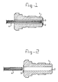
- Figure 1 shows a section through a first embodiment of an optical pressure sensor for an internal combustion engine.
- Figure 2 shows a second embodiment
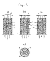
- Figures 3a, 3b and 3c show diagrammatically the operation of the pressure sensor in three positions of the membrane.
- Figure 3d shows a section of the fibre assembly.
- the pressure sensors shown comprise a bolt 1 to be screwed into a threaded opening in the wall of an internal combustion engine, in particular a diesel pump, which bolt is provided with a through bore 2, a membrane 3 provided at one end of the bolt and an optical fibre assembly 4 which in Figure 1 does, and in Figure 2 does not, project into the bore 2.
- the membrane surface facing the fibre assembly is reflective.
- the optical fibre assembly comprises three sheath-type optical fibre groups: a light-input fibre group 5 having a light-output fibre group 6 or 7, respectively, on either side.
- Figures 3a, 3b and 3c consecutively show the case where the pressure in the pump is higher than, equal to, and lower than the atmospheric pressure.
- the bulging of the membrane is a measure of the pressure in the internal combustion engine.
- the membrane reflects appreciably more light via the innermost fibre sheath 7 than via the outermost fibre sheath 6.
- it is the other way round, while in Figure 3b equally as much light is reflected via both fibre sheaths 6 and 7.
- the ratio of the light reflected via the sheath 6 to the light reflected via the sheath 7 is a measure of the bulging of the membrane, that is to say, of the pressure difference on either side of the membrane.
- the sensor is relatively insensitive to vibrations and emminently suitable for pressure measurements in an internal combustion engine, in particular a diesel engine.
- the bore 2 will be sealed by a plug or head. This is temporarily removed during measurement.
- the fibre assembly is not inserted into the bore 2 in the embodiment according to Figure 2 (the membrane is provided at the head of the bolt), the fibre assembly can be replaced by a central light source and two concentric photodiodes.
- the fibre assembly or the central light source with photodiodes will normally only be placed in or near the bolt during measurement.
Abstract
Description
- The invention relates to an optical pressure sensor for determining the variation of the pressure in an internal combustion engine, comprising a bolt having a through bore, a membrane which is mounted in the bore or at one end of said bore and at least one surface of which is reflective, means for causing light to fall on the reflective membrane part and means for measuring the light reflected at the membrane or guiding it to a light-measuring device.
- Such a sensor is disclosed by GB-A-2,186,360. In that case, both the means for causing light to fall on the reflective membrane part and the means for guiding the light reflected at the membrane to a light-measuring device consist of separate bundles of optical fibres. Said sensor is cheap to manufacture and easy to install. The susceptibility to malfunction is also low. A drawback of the known sensor is that it is sensitive to the intensity of the light source, the spacing between the bundles of optical fibres and the membrane, the light loss in the input fibres, variations in the reflecting power of the reflective membrane surface and the ambient temperature. In view of this, the bundles of optical fibres will have to be accurately positioned.
- The object of the invention is to avoid these drawbacks and for this purpose the pressure sensor referred to in the preamble is characterised in that the means for causing light to fall on the reflective membrane part have the form of a ring or sheath, in that means are situated both inside the ring or sheath and around the ring or sheath for measuring light reflected at the membrane or guiding it to a light-measuring device, and in that the pressure drop across the membrane is determined from the ratio of the reflected light which is received via the means provided around said ring or sheath and the reflected light which is received via the means provided in the ring or sheath.
- Since the pressure difference is determined from the abovementioned ratio, the measurement result is independent of an accurate positioning of the said means.
- Preferably, use is made of an optical fibre assembly consisting of three concentric bundles of light-transmitting fibres.
- In a variant, use is made of an annular light source and two concentric photodiodes.
- The invention will now be explained in greater detail by reference to the figures.
- Figure 1 shows a section through a first embodiment of an optical pressure sensor for an internal combustion engine.
- Figure 2 shows a second embodiment.
- Figures 3a, 3b and 3c show diagrammatically the operation of the pressure sensor in three positions of the membrane.
- Figure 3d shows a section of the fibre assembly.
- The pressure sensors shown comprise a bolt 1 to be screwed into a threaded opening in the wall of an internal combustion engine, in particular a diesel pump, which bolt is provided with a through
bore 2, amembrane 3 provided at one end of the bolt and anoptical fibre assembly 4 which in Figure 1 does, and in Figure 2 does not, project into thebore 2. The membrane surface facing the fibre assembly is reflective. - As is evident from Figure 3, the optical fibre assembly comprises three sheath-type optical fibre groups: a light-
input fibre group 5 having a light-output fibre group - Figures 3a, 3b and 3c consecutively show the case where the pressure in the pump is higher than, equal to, and lower than the atmospheric pressure. The bulging of the membrane is a measure of the pressure in the internal combustion engine. In the case of Figure 3a, the membrane reflects appreciably more light via the
innermost fibre sheath 7 than via theoutermost fibre sheath 6. In the case of Figure 3c, it is the other way round, while in Figure 3b equally as much light is reflected via bothfibre sheaths sheath 6 to the light reflected via thesheath 7 is a measure of the bulging of the membrane, that is to say, of the pressure difference on either side of the membrane. - The sensor is relatively insensitive to vibrations and emminently suitable for pressure measurements in an internal combustion engine, in particular a diesel engine. In order to prevent contamination of the reflective membrane, the
bore 2 will be sealed by a plug or head. This is temporarily removed during measurement. - Because the fibre assembly is not inserted into the
bore 2 in the embodiment according to Figure 2 (the membrane is provided at the head of the bolt), the fibre assembly can be replaced by a central light source and two concentric photodiodes. The fibre assembly or the central light source with photodiodes will normally only be placed in or near the bolt during measurement.
Claims (3)
- Optical pressure sensor for determining the variation of the pressure in an internal combustion engine, comprising a bolt (1) having a through bore (2), a membrane (3) which is mounted in the bore or at one end of said bore and at least one surface of which is reflective, means (5) for causing light to fall on the reflective membrane part and means (6, 7) for measuring the light reflected at the membrane or guiding it to a light-measuring device, characterised in that the means for causing light to fall on the reflective membrane part have the form of a ring or sheath (5), in that means (7 or 6, respectively) are situated both inside the ring or sheath (5) and around the ring or sheath (5) for measuring light reflected at the membrane or guiding it to a light measuring device, and in that the pressure drop across the membrane is determined from the ratio of the reflected light which is received via the means (6) provided around said ring or sheath (5) and the reflected light which is received via the means (7) provided in the ring or sheath (5).
- Optical pressure sensor according to Claim 1, characterised by an optical fibre assembly consisting of three concentric bundles of light-transmitting fibres (5, 6, 7).
- Optical pressure sensor according to Claim 1, characterised by an annular light source and two concentric photodiodes.
Priority Applications (1)
| Application Number | Priority Date | Filing Date | Title |
|---|---|---|---|
| AT90203523T ATE95280T1 (en) | 1990-04-05 | 1990-12-28 | OPTICAL PRESSURE SENSOR FOR DETECTING PRESSURE VARIATIONS IN AN ENGINE. |
Applications Claiming Priority (2)
| Application Number | Priority Date | Filing Date | Title |
|---|---|---|---|
| NL9000801 | 1990-04-05 | ||
| NL9000801A NL9000801A (en) | 1990-04-05 | 1990-04-05 | COMBUSTION ENGINE WITH OPTICAL PRESSURE SENSOR. |
Publications (2)
| Publication Number | Publication Date |
|---|---|
| EP0451374A1 true EP0451374A1 (en) | 1991-10-16 |
| EP0451374B1 EP0451374B1 (en) | 1993-09-29 |
Family
ID=19856870
Family Applications (1)
| Application Number | Title | Priority Date | Filing Date |
|---|---|---|---|
| EP90203523A Expired - Lifetime EP0451374B1 (en) | 1990-04-05 | 1990-12-28 | Optical pressure sensor for determining the variation of the pressure in an internal combustion engine |
Country Status (4)
| Country | Link |
|---|---|
| EP (1) | EP0451374B1 (en) |
| AT (1) | ATE95280T1 (en) |
| DE (1) | DE69003674T2 (en) |
| NL (1) | NL9000801A (en) |
Cited By (1)
| Publication number | Priority date | Publication date | Assignee | Title |
|---|---|---|---|---|
| WO1992008112A1 (en) * | 1990-10-24 | 1992-05-14 | Ford Motor Company Limited | Mounting a sensor in a combustion chamber |
Citations (4)
| Publication number | Priority date | Publication date | Assignee | Title |
|---|---|---|---|---|
| US3580082A (en) * | 1969-11-07 | 1971-05-25 | Bendix Corp | Pressure transducer |
| US4158310A (en) * | 1978-01-30 | 1979-06-19 | University Of Southern California | Optical pressure transducer of randomly distributed fiber optics |
| EP0208545A2 (en) * | 1985-07-10 | 1987-01-14 | Hitachi, Ltd. | Method and apparatus for detecting combustion pressure in engine |
| GB2186360A (en) * | 1986-02-07 | 1987-08-12 | Ford Motor Co | Stress transducer |
-
1990
- 1990-04-05 NL NL9000801A patent/NL9000801A/en not_active Application Discontinuation
- 1990-12-28 DE DE90203523T patent/DE69003674T2/en not_active Expired - Fee Related
- 1990-12-28 EP EP90203523A patent/EP0451374B1/en not_active Expired - Lifetime
- 1990-12-28 AT AT90203523T patent/ATE95280T1/en active
Patent Citations (4)
| Publication number | Priority date | Publication date | Assignee | Title |
|---|---|---|---|---|
| US3580082A (en) * | 1969-11-07 | 1971-05-25 | Bendix Corp | Pressure transducer |
| US4158310A (en) * | 1978-01-30 | 1979-06-19 | University Of Southern California | Optical pressure transducer of randomly distributed fiber optics |
| EP0208545A2 (en) * | 1985-07-10 | 1987-01-14 | Hitachi, Ltd. | Method and apparatus for detecting combustion pressure in engine |
| GB2186360A (en) * | 1986-02-07 | 1987-08-12 | Ford Motor Co | Stress transducer |
Non-Patent Citations (1)
| Title |
|---|
| PATENT ABSTRACTS OF JAPAN, vol. 10, no. 132 (P-456)[2189] 16 May 1986; & JP-A-60 253 930 (NIPPON DENKI K.K.) 14 December 1985, * |
Cited By (1)
| Publication number | Priority date | Publication date | Assignee | Title |
|---|---|---|---|---|
| WO1992008112A1 (en) * | 1990-10-24 | 1992-05-14 | Ford Motor Company Limited | Mounting a sensor in a combustion chamber |
Also Published As
| Publication number | Publication date |
|---|---|
| EP0451374B1 (en) | 1993-09-29 |
| DE69003674D1 (en) | 1993-11-04 |
| ATE95280T1 (en) | 1993-10-15 |
| NL9000801A (en) | 1991-11-01 |
| DE69003674T2 (en) | 1994-01-27 |
Similar Documents
| Publication | Publication Date | Title |
|---|---|---|
| US4745293A (en) | Method and apparatus for optically measuring fluid levels | |
| US4158310A (en) | Optical pressure transducer of randomly distributed fiber optics | |
| US5421195A (en) | Fiber optic microbend sensor for engine knock and misfire detection | |
| US4994682A (en) | Fiber optic continuous liquid level sensor | |
| US6649924B1 (en) | Optoelectronic measuring device | |
| US7340118B2 (en) | Fuel injectors with integral fiber optic pressure sensors and associated compensation and status monitoring devices | |
| US5390546A (en) | Fiber optic diaphragm sensors for engine knock and misfire detection | |
| EP1015855B1 (en) | Fuel injectors with integral fiber optic pressure sensors and associated compensation and status monitoring devices | |
| US4870292A (en) | Fibre optic sensor for liquid level and other parameters | |
| US6820488B2 (en) | Fiber-optic pressure sensor | |
| US5399876A (en) | Optical point level sensor with lens | |
| EP0823621A3 (en) | Apparatus for detecting a fault location in an optical fiber line | |
| GB2090095A (en) | Measuring signal transmission device for transmitting optical signals between a rotating portion and a rotationally stationary portion | |
| CA1332205C (en) | Fibre optic sensors for the continuous measurement of liquid level and other parameters | |
| US4355898A (en) | Optical detecting, monitoring or measuring arrangements | |
| EP0451374B1 (en) | Optical pressure sensor for determining the variation of the pressure in an internal combustion engine | |
| US20120161034A1 (en) | Sensor system for fluid detection and discrimination | |
| US4403152A (en) | Optical fiber position sensor | |
| US5349181A (en) | Fiber optic chemical sensor having specific channel connecting design | |
| US8084731B2 (en) | Sensor system for liquid detection with lens component having an apex | |
| SU1076787A1 (en) | Photoelectric pressure pickup | |
| SU1686321A1 (en) | Device for measuring sound pressure | |
| EP0075422A3 (en) | Measuring performance of reflex reflectors | |
| SU1753259A1 (en) | Linear movement optical converter | |
| SU956999A1 (en) | Optical electronic vibration pickup |
Legal Events
| Date | Code | Title | Description |
|---|---|---|---|
| PUAI | Public reference made under article 153(3) epc to a published international application that has entered the european phase |
Free format text: ORIGINAL CODE: 0009012 |
|
| AK | Designated contracting states |
Kind code of ref document: A1 Designated state(s): AT BE CH DE DK ES FR GB GR IT LI LU NL SE |
|
| 17P | Request for examination filed |
Effective date: 19920317 |
|
| 17Q | First examination report despatched |
Effective date: 19930309 |
|
| GRAA | (expected) grant |
Free format text: ORIGINAL CODE: 0009210 |
|
| AK | Designated contracting states |
Kind code of ref document: B1 Designated state(s): AT BE CH DE DK ES FR GB GR IT LI LU NL SE |
|
| PG25 | Lapsed in a contracting state [announced via postgrant information from national office to epo] |
Ref country code: IT Free format text: LAPSE BECAUSE OF FAILURE TO SUBMIT A TRANSLATION OF THE DESCRIPTION OR TO PAY THE FEE WITHIN THE PRE;WARNING: LAPSES OF ITALIAN PATENTS WITH EFFECTIVE DATE BEFORE 2007 MAY HAVE OCCURRED AT ANY TIME BEFORE 2007. THE CORRECT EFFECTIVE DATE MAY BE DIFFERENT FROM THE ONE RECORDED.SCRIBED TIME-LIMIT Effective date: 19930929 Ref country code: AT Effective date: 19930929 Ref country code: BE Effective date: 19930929 Ref country code: CH Effective date: 19930929 Ref country code: NL Effective date: 19930929 Ref country code: GR Free format text: LAPSE BECAUSE OF FAILURE TO SUBMIT A TRANSLATION OF THE DESCRIPTION OR TO PAY THE FEE WITHIN THE PRESCRIBED TIME-LIMIT Effective date: 19930929 Ref country code: ES Free format text: THE PATENT HAS BEEN ANNULLED BY A DECISION OF A NATIONAL AUTHORITY Effective date: 19930929 Ref country code: DK Effective date: 19930929 Ref country code: SE Effective date: 19930929 Ref country code: LI Effective date: 19930929 |
|
| REF | Corresponds to: |
Ref document number: 95280 Country of ref document: AT Date of ref document: 19931015 Kind code of ref document: T |
|
| REF | Corresponds to: |
Ref document number: 69003674 Country of ref document: DE Date of ref document: 19931104 |
|
| PG25 | Lapsed in a contracting state [announced via postgrant information from national office to epo] |
Ref country code: LU Free format text: LAPSE BECAUSE OF NON-PAYMENT OF DUE FEES Effective date: 19931231 |
|
| ET | Fr: translation filed | ||
| REG | Reference to a national code |
Ref country code: CH Ref legal event code: PL |
|
| NLV1 | Nl: lapsed or annulled due to failure to fulfill the requirements of art. 29p and 29m of the patents act | ||
| PLBE | No opposition filed within time limit |
Free format text: ORIGINAL CODE: 0009261 |
|
| STAA | Information on the status of an ep patent application or granted ep patent |
Free format text: STATUS: NO OPPOSITION FILED WITHIN TIME LIMIT |
|
| 26N | No opposition filed | ||
| PGFP | Annual fee paid to national office [announced via postgrant information from national office to epo] |
Ref country code: DE Payment date: 19941104 Year of fee payment: 5 |
|
| PG25 | Lapsed in a contracting state [announced via postgrant information from national office to epo] |
Ref country code: DE Effective date: 19960903 |
|
| PGFP | Annual fee paid to national office [announced via postgrant information from national office to epo] |
Ref country code: GB Payment date: 20011102 Year of fee payment: 12 |
|
| PGFP | Annual fee paid to national office [announced via postgrant information from national office to epo] |
Ref country code: FR Payment date: 20011203 Year of fee payment: 12 |
|
| REG | Reference to a national code |
Ref country code: GB Ref legal event code: IF02 |
|
| PG25 | Lapsed in a contracting state [announced via postgrant information from national office to epo] |
Ref country code: GB Free format text: LAPSE BECAUSE OF NON-PAYMENT OF DUE FEES Effective date: 20021228 |
|
| GBPC | Gb: european patent ceased through non-payment of renewal fee |
Effective date: 20021228 |
|
| PG25 | Lapsed in a contracting state [announced via postgrant information from national office to epo] |
Ref country code: FR Free format text: LAPSE BECAUSE OF NON-PAYMENT OF DUE FEES Effective date: 20030901 |
|
| REG | Reference to a national code |
Ref country code: FR Ref legal event code: ST |