EP0451306B1 - Frequency-selective laminated ultrasound transducer - Google Patents
Frequency-selective laminated ultrasound transducer Download PDFInfo
- Publication number
- EP0451306B1 EP0451306B1 EP90106773A EP90106773A EP0451306B1 EP 0451306 B1 EP0451306 B1 EP 0451306B1 EP 90106773 A EP90106773 A EP 90106773A EP 90106773 A EP90106773 A EP 90106773A EP 0451306 B1 EP0451306 B1 EP 0451306B1
- Authority
- EP
- European Patent Office
- Prior art keywords
- ultrasonic transducer
- laminated ultrasonic
- transducer according
- laminated
- breakage
- Prior art date
- Legal status (The legal status is an assumption and is not a legal conclusion. Google has not performed a legal analysis and makes no representation as to the accuracy of the status listed.)
- Expired - Lifetime
Links
- 238000002604 ultrasonography Methods 0.000 title claims description 20
- 239000011521 glass Substances 0.000 claims abstract description 20
- 238000001228 spectrum Methods 0.000 claims abstract description 10
- 239000000463 material Substances 0.000 claims description 7
- 239000000945 filler Substances 0.000 claims description 4
- 238000013016 damping Methods 0.000 claims description 2
- 230000011664 signaling Effects 0.000 claims 2
- 238000001514 detection method Methods 0.000 abstract description 7
- 230000035945 sensitivity Effects 0.000 abstract description 7
- 230000010355 oscillation Effects 0.000 abstract description 2
- 238000001914 filtration Methods 0.000 abstract 1
- 238000011156 evaluation Methods 0.000 description 7
- 238000013017 mechanical damping Methods 0.000 description 3
- 239000000919 ceramic Substances 0.000 description 2
- 239000002131 composite material Substances 0.000 description 2
- 238000010586 diagram Methods 0.000 description 2
- 238000000034 method Methods 0.000 description 2
- QXJJQWWVWRCVQT-UHFFFAOYSA-K calcium;sodium;phosphate Chemical compound [Na+].[Ca+2].[O-]P([O-])([O-])=O QXJJQWWVWRCVQT-UHFFFAOYSA-K 0.000 description 1
- 238000000295 emission spectrum Methods 0.000 description 1
- 239000003822 epoxy resin Substances 0.000 description 1
- 238000004519 manufacturing process Methods 0.000 description 1
- 238000005293 physical law Methods 0.000 description 1
- 239000004033 plastic Substances 0.000 description 1
- 229920000647 polyepoxide Polymers 0.000 description 1
- 230000001052 transient effect Effects 0.000 description 1
Images
Classifications
-
- B—PERFORMING OPERATIONS; TRANSPORTING
- B06—GENERATING OR TRANSMITTING MECHANICAL VIBRATIONS IN GENERAL
- B06B—METHODS OR APPARATUS FOR GENERATING OR TRANSMITTING MECHANICAL VIBRATIONS OF INFRASONIC, SONIC, OR ULTRASONIC FREQUENCY, e.g. FOR PERFORMING MECHANICAL WORK IN GENERAL
- B06B1/00—Methods or apparatus for generating mechanical vibrations of infrasonic, sonic, or ultrasonic frequency
- B06B1/02—Methods or apparatus for generating mechanical vibrations of infrasonic, sonic, or ultrasonic frequency making use of electrical energy
- B06B1/06—Methods or apparatus for generating mechanical vibrations of infrasonic, sonic, or ultrasonic frequency making use of electrical energy operating with piezoelectric effect or with electrostriction
- B06B1/0644—Methods or apparatus for generating mechanical vibrations of infrasonic, sonic, or ultrasonic frequency making use of electrical energy operating with piezoelectric effect or with electrostriction using a single piezoelectric element
- B06B1/0662—Methods or apparatus for generating mechanical vibrations of infrasonic, sonic, or ultrasonic frequency making use of electrical energy operating with piezoelectric effect or with electrostriction using a single piezoelectric element with an electrode on the sensitive surface
- B06B1/067—Methods or apparatus for generating mechanical vibrations of infrasonic, sonic, or ultrasonic frequency making use of electrical energy operating with piezoelectric effect or with electrostriction using a single piezoelectric element with an electrode on the sensitive surface which is used as, or combined with, an impedance matching layer
-
- G—PHYSICS
- G10—MUSICAL INSTRUMENTS; ACOUSTICS
- G10K—SOUND-PRODUCING DEVICES; METHODS OR DEVICES FOR PROTECTING AGAINST, OR FOR DAMPING, NOISE OR OTHER ACOUSTIC WAVES IN GENERAL; ACOUSTICS NOT OTHERWISE PROVIDED FOR
- G10K9/00—Devices in which sound is produced by vibrating a diaphragm or analogous element, e.g. fog horns, vehicle hooters or buzzers
- G10K9/12—Devices in which sound is produced by vibrating a diaphragm or analogous element, e.g. fog horns, vehicle hooters or buzzers electrically operated
- G10K9/122—Devices in which sound is produced by vibrating a diaphragm or analogous element, e.g. fog horns, vehicle hooters or buzzers electrically operated using piezoelectric driving means
Definitions
- the invention relates to an ultrasound film converter.
- Previously known ultrasound layer transducers are designed as broadband near-distance transducers (EP 0 154 706 A2) or as wide-beam proximity sensors. They have high mechanical damping, ie low sensitivity, and are comparatively expensive due to the high material and manufacturing costs.
- Another disadvantage of previously known ultrasonic layer transducers is their narrow directional diagram in certain frequency ranges, which is undesirable, for example, when used for all-round detection of glass breakages, for example in motor vehicles.
- Conventional converters with a very large bandwidth can be used for this application, which absorb the ultrasonic vibrations emitted when a glass plate is broken and convert them into an electrical signal with corresponding frequencies.
- the break frequencies that are typical for glass breakage enable a glass pane break to be detected by means of an evaluation circuit downstream of the ultrasound transducer.
- the evaluation device must first separate the break frequencies mentioned, for example by filters, from the entire spectrum in which the ultrasonic transducer is sensitive; because only the signals occurring at the relevant break frequencies are relevant for the detection of a broken glass pane.
- an ultrasound layer transducer which is only sensitive to certain frequencies, such as the breakage frequencies when a glass pane is broken, in order in this way to to be able to do without filters otherwise necessary in the evaluation circuit or at least to be able to keep the effort for the filters low.
- the object is achieved in that at least one of the geometrical dimensions of the ultrasound layer transducer is specifically adapted to the frequency selectivity required of it with regard to the bridging frequencies typical of glass breakage.
- the objects according to claims 2 and 3 represent advantageous configurations.
- the objects according to claims 3 to 5 are also advantageously designed, since the mechanical damping of the ultrasound layer converter can be varied within wide limits by adding fillers. The range of converter modes can thus be increased in a targeted and defined manner if an additional evaluation of oscillation processes is desired. If an evaluation device is connected downstream of the ultrasound layer converter, with which received ultrasound spectra can be compared and evaluated with the ultrasound spectrum typical for glass breakage, this represents a simple embodiment for the detection of a glass pane break. A further simplification is provided if the glass breakage detection arrangement contains a microprocessor for storing the contains ultrasound spectra typical for glass breakage.
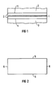
- the 1 shows an ultrasound layer transducer with a rectangular piezoceramic plate 1, which is preferably surrounded on both sides by a layer 2 of plastic material with low acoustic impedance.
- the two layers 2 consist, for example, of epoxy resin filled with hollow glass spheres.
- the geometrical external dimensions of the cuboid ultrasonic layer transducer are coordinated so that the effective sound velocities of the plastic-ceramic composite result in narrow-band resonance points of sensitivity at the frequencies at which the characteristic maxima also occur in the glass breakage spectrum to be evaluated.
- the glass breakage emission can thus advantageously be registered frequency-selectively with high sensitivity.
- the plastic-ceramic composite mentioned is surrounded by elastic embedding material 3, which contains variable fillers for damping.
- the narrow long side 5 or broad side 6 of the ultrasonic layer transducer can be used as a sound-receiving surface. It is kept free of the embedding material 3.
- the dimensions of such an ultrasound layer transducer can be, for example, 20 ⁇ 10 ⁇ 2 mm, the piezoceramic plate having dimensions of, for example, 20 ⁇ 10 ⁇ 0.2 mm.
- Such an ultrasonic layer converter has selective reception sensitivity at 60 and 120 kHz.
- the narrow long side is used as the sound-receiving surface.
- the broad part of the astigmatic directional diagram is greater than 120 ° at both frequencies.
- This ultrasonic layer converter is therefore suitable for use, for example, in a glass breakage detector for motor vehicles; because this ultrasonic layer converter is robust and inexpensive and also has a high sensitivity in a wide opening angle range (greater than 120 °). This enables the interior of a motor vehicle to be monitored by a single ultrasound slice converter.
- 1 instead of a rectangular shape of the piezoceramic plate Shapes, such as round shapes or other polygon shapes can be realized.
- the resonance frequencies mentioned above are calculated according to the known physical laws, i.e. they depend on the speed of sound in the material as well as on the dimensions. Due to the cuboid structure, there are therefore three basic resonances, namely in addition to the longitudinal resonance and a width and thickness resonance. In circular disc designs, there are the fundamental vibration modes of the thickness vibration and the radial vibration. If you want to utilize additional vibration modes and thus frequencies, you can use the harmonics of the respective vibrations, the frequencies of which are in multiples of the fundamental vibration.
- the use of such an ultrasonic transducer is not limited to glass breakage detection.
- the selective tuning of the transducer resonance frequencies can also be carried out for the spectrum of other ultrasound emissions to be measured. E.g. the characteristic emission spectrum of moving machine parts can be examined in order to test these parts for functionality or wear.
Landscapes
- Engineering & Computer Science (AREA)
- Mechanical Engineering (AREA)
- Physics & Mathematics (AREA)
- Acoustics & Sound (AREA)
- Multimedia (AREA)
- Investigating Or Analyzing Materials By The Use Of Ultrasonic Waves (AREA)
- Burglar Alarm Systems (AREA)
- Transducers For Ultrasonic Waves (AREA)
Abstract
Description
Die Erfindung betrifft einen Ultraschall-Schichtwandler.The invention relates to an ultrasound film converter.
Bisher bekannte Ultraschall-Schichtwandler sind als breitbandige Nahdistanzwandler (EP 0 154 706 A2) oder als breitstrahlende Näherungssensoren konzipiert. Sie weisen eine hohe mechanische Dämpfung, d.h. geringe Empfindlichkeit auf und sind infolge hoher Material- und Fertigungskosten vergleichsweise teuer. Ein weiterer Nachteil bisher bekannter Ultraschall-Schichtwandler ist ihr schmales Richtdiagramm in bestimmten Frequenzbereichen, was beispielsweise beim Einsatz zur Rundum-Detektion von Glasbrüchen, z.B. in Kraftfahrzeugen, unerwünscht ist. Für diesen Anwendungsfall können zwar herkömmliche Wandler mit sehr großer Bandbreite verwendet werden, die die beim Brechen einer Glasplatte abgestrahlten Ultraschall-Schwingungen aufnehmen und diese in ein elektrisches Signal mit entsprechenden Frequenzen umwandeln. Die beim Glasbruch typischen Bruchfrequenzen ermöglichen mittels einer dem Ultraschallwandler nachgeschalteten Auswerteschaltung, einen Glasscheibenbruch zu erkennen. Das Auswertegerät muß hierbei zunächst aus dem gesamten Spektrum, in dem der Ultraschallwandler empfindlich ist, die genannten Bruchfrequenzen, z.B. durch Filter, heraustrennen; denn nur die an den betreffenden Bruchfrequenzen auftretenden Signale sind zur Feststellung eines Glasscheibenbruchs relevant. Um z.B. eine solche Auswerteeinrichtung einer Glasbruchmeldeanordnung zu vereinfachen und damit auch Kosten zu sparen, wäre es vorteilhaft, einen Ultraschall-Schichtwandler einzusetzen, der nur für bestimmte Frequenzen, wie z.B. die Bruchfrequenzen beim Brechen einer Glasscheibe, empfindlich ist, um auf diese Weise auf den ansonsten in der Auswerteschaltung notwendigen Filter verzichten zu können oder wenigstens den Aufwand bei den Filtern gering halten zu können.Previously known ultrasound layer transducers are designed as broadband near-distance transducers (EP 0 154 706 A2) or as wide-beam proximity sensors. They have high mechanical damping, ie low sensitivity, and are comparatively expensive due to the high material and manufacturing costs. Another disadvantage of previously known ultrasonic layer transducers is their narrow directional diagram in certain frequency ranges, which is undesirable, for example, when used for all-round detection of glass breakages, for example in motor vehicles. Conventional converters with a very large bandwidth can be used for this application, which absorb the ultrasonic vibrations emitted when a glass plate is broken and convert them into an electrical signal with corresponding frequencies. The break frequencies that are typical for glass breakage enable a glass pane break to be detected by means of an evaluation circuit downstream of the ultrasound transducer. The evaluation device must first separate the break frequencies mentioned, for example by filters, from the entire spectrum in which the ultrasonic transducer is sensitive; because only the signals occurring at the relevant break frequencies are relevant for the detection of a broken glass pane. For example, to simplify such an evaluation device for a glass breakage detection arrangement and thus also to save costs, it would be advantageous to use an ultrasound layer transducer which is only sensitive to certain frequencies, such as the breakage frequencies when a glass pane is broken, in order in this way to to be able to do without filters otherwise necessary in the evaluation circuit or at least to be able to keep the effort for the filters low.
Daher liegt der Erfindung die Aufgabe zugrunde, einen Ultraschall-Schichtwandler zu schaffen, der für bestimmte vorzugebende Frequenzen hohe Ansprechempfindlichkeit aufweist.It is therefore an object of the invention to provide an ultrasound layer converter which has high sensitivity for certain frequencies to be specified.
Diese Aufgabe wird dadurch gelöst, daß zumindest eine der geometrischen Abmessungen des Ultraschall-Schichtwandlers gezielt der an ihn geforderten Frequenzselektivität hinsichtlich der bei Glasbruch typischen Bruckfrequenzen angepaßt ist. Die Gegenstände nach Anspruch 2 und 3 stellen vorteilhafte Ausgestaltungen dar. Ebenfalls sind auch die Gegenstände gemäß Anspruch 3 bis 5 vorteilhaft ausgebildet, da hier mittels der Zugabe von Füllstoffen die mechanische Dämpfung des Ultraschall-Schichtwandlers in weiten Grenzen variierbar ist. Die Bandbreite der Wandlermoden kann somit gezielt und definiert vergrößert werden, wenn eine zusätzliche Auswertung von schwingvorgängen gewünscht wird. Ist dem Ultraschall-Schichtwandler ein Auswertegerät nachgeschaltet, mit welchem empfangene Ultraschallspektren mit dem für Glasbruch typischen Ultraschallspektrum vergleichbar und auswertbar sind, so stellt dies eine einfache Ausführung zur Detektion eines Glasscheibenbruchs dar. Eine weitere Vereinfachung ist gegeben, wenn die Glasbruchmeldeanordnung einen Mikroprozessor zur Abspeicherung des für Glasbruch typischen Ultraschallspektrums enthält.This object is achieved in that at least one of the geometrical dimensions of the ultrasound layer transducer is specifically adapted to the frequency selectivity required of it with regard to the bridging frequencies typical of glass breakage. The objects according to
Ein Ausführungsbeispiel der Erfindung wird im folgenden anhand einer Zeichnung näher erläutert.An embodiment of the invention is explained below with reference to a drawing.
Es zeigen:
- FIG 1 einen Querschnitt eines Ultraschall-Schichtwandlers und
- FIG 2 eine Draufsicht desselben.
- 1 shows a cross section of an ultrasonic layer transducer and
- 2 shows a plan view of the same.
In FIG 1 ist ein Ultraschall-Schichtwandler mit einem rechteckigen Piezokeramikplättchen 1 dargestellt, das vorzugsweise beidseits von jeweils einer Schicht 2 aus Kunststoffmaterial niedriger akustischer Impedanz umgeben ist. Die beiden Schichten 2 bestehen z.B. aus mit Hohglaskugeln gefülltem Epoxidharz. Die geometrischen Außenmaße des quaderförmigen Ultraschall-Schichtwandlers sind so abgestimmt, daß sich mit den effektiven Schallgeschwindigkeiten des Kunststoff-Keramik-Verbundes schmalbandige Resonanzstellen der Empfindlichkeit bei den Frequenzen ergeben, bei denen auch im auszuwertenden Glasbruchspektrum die charakteristischen Maxima auftreten. Somit kann vorteilhafterweise die Glasbruch-Emission frequenzselektiv mit hoher Empfindlichkeit registriert werden. Der genannte Kunststoff-Keramik-Verbund ist von elastischem Einbettmaterial 3 umgeben, welches mengenmäßig variierbare Füllstoffe zur Dämpfung enthält. Dies bedeutet, daß durch Zugabe der Füllstoffe die mechanische Dämpfung des elastischen Einbettmaterials 3 in weiten Grenzen veränderbar ist. So kann die Bandbreite der Wandlermoden gezielt und definiert vergrößert werden, wenn eine zusätzliche Auswertung von Einschwingvorgängen gewünscht wird. Die schmale Längs- 5 oder Breitseite 6 des Ultraschall-Schichtwandlers kann als schallempfangende Oberfläche benutzt werden. Sie wird von dem Einbettmaterial 3 freigehalten. Die Abmessungen eines derartigen Ultraschall-Schichtwandlers können beispielsweise 20 × 10 × 2 mm betragen, wobei das Piezokeramikplättchen Abmessungen von beispielsweise 20 × 10 × 0,2 mm aufweist. Ein solcher Ultraschall-Schichtwandler besitzt selektive Empfangsempfindlichkeit bei 60 und 120 kHz. Als schallempfangende Fläche wird die schmale Längsseite benutzt. Der breite Teil des astigmatischen Richtdiagramms ist hier bei beiden Frequenzen größer als 120°. Somit ist dieser Ultraschall-Schichtwandler zum Einsatz z.B. in einem Glasbruchdetektor für Kraftfahrzeuge geeignet; denn dieser Ultraschall-Schichtwandler ist robust und kostengünstig und hat zudem in einem weiten Öffnungswinkelbereich (größer 120°) eine hohe Empfindlichkeit. Damit ist die Möglichkeit gegeben, den Innenraum einen Kraftfahrzeugs durch einen einzigen Ultraschall-Schichtwandler zu überwachen. Abweichend von der dargestellten Ausführungsform ist die Ausbildung eines Ultraschall-Schichtwandlers möglich, dessen Piezokeramikplättchen 1 nur auf einer Seite mit einer Schicht 2 niedriger akustischer Impedanz umgeben ist. Außerdem sind anstelle einer Rechteckform des Piezokeramikplättchens 1 andere Formen, z.B. runde Formen oder andere Vieleckformen realisierbar.1 shows an ultrasound layer transducer with a rectangular
Die obengenannten Resonanzfrequenzen berechnen sich nach den bekannten physikalischen Gesetzen, d.h. sie hängen sowohl von der Schallgeschwindigkeit im Material als auch von den Abmessungen ab. Aufgrund des quaderförmigen Aufbaus gibt es demnach drei Grund-Resonanzen, nämlich neben der Längsresonanz auch eine Breiten- und Dickenresonanz. Bei kreisscheibenförmigen Ausführungen gibt es die Grundschwingungsmoden der Dickenschwingung und der Radialschwingung. Will man noch zusätzliche Schwingungsmoden und damit-frequenzen ausnutzen, kann man die Oberwellen der jeweiligen Schwingungen heranziehen, deren Frequenzen bei Vielfachen der Grundschwingung liegen.The resonance frequencies mentioned above are calculated according to the known physical laws, i.e. they depend on the speed of sound in the material as well as on the dimensions. Due to the cuboid structure, there are therefore three basic resonances, namely in addition to the longitudinal resonance and a width and thickness resonance. In circular disc designs, there are the fundamental vibration modes of the thickness vibration and the radial vibration. If you want to utilize additional vibration modes and thus frequencies, you can use the harmonics of the respective vibrations, the frequencies of which are in multiples of the fundamental vibration.
Der Einsatz eines derartigen Ultraschallwandlers ist aber nicht auf Glasbruchdetektion beschränkt. Die selektive Abstimmung der Wandler-Resonanzfrequenzen kann auch für das zu messende Spektrum anderer Ultraschallemissionen erfolgen. Z.B. kann das charakteristische Emissionsspektrum von bewegten Maschinenteilen untersucht werden, um diese Teile auf Funktionsfähigkeit oder Verschleiß zu prüfen.The use of such an ultrasonic transducer is not limited to glass breakage detection. The selective tuning of the transducer resonance frequencies can also be carried out for the spectrum of other ultrasound emissions to be measured. E.g. the characteristic emission spectrum of moving machine parts can be examined in order to test these parts for functionality or wear.
Claims (8)
- Laminated ultrasonic transducer, characterised in that at least one of its geometrical dimensions is matched in a controlled manner to the frequency selectivity demanded of it with regard to the frequencies of breakage which are typical of glass breakage.
- Laminated ultrasonic transducer according to claim 1, characterised in that it has a thin piezoceramic plate (1) which is surrounded on at least one of its two plate surfaces by a layer (2) of low acoustic impedance.
- Laminated ultrasonic transducer according to claim 1 or 2, characterised in that at least one of the dimensions of height, length and width of this parallelepiped block-shaped body is determined such that it corresponds to a desired fundamental frequency.
- Laminated ultrasonic transducer according to claim 2 or 3, characterised in that it is surrounded, on its large outer surfaces (4) of the two layers, by elastic embedding material (3) which for damping purposes contains fillers, the quantities of which are predetermined.
- Laminated ultrasonic transducer according to claim 3, characterised in that the narrow longitudinal side (5) or broad side (6) can be used as a sound-receiving surface.
- Laminated ultrasonic transducer according to one of the preceding claims, characterised in that it is a component part of a glass-breakage signalling arrangement.
- Laminated ultrasonic transducer according to claim 6, characterised in that connected downstream of the laminated ultrasonic transducer there is an evaluating device with which the received ultrasound spectrum can be compared with the ultrasound spectrum typical of glass breakage and can be evaluated.
- Laminated ultrasonic transducer according to claim 6 or 7, characterised in that the glass-breakage signalling arrangement contains a microprocessor for storing the ultrasound spectrum which is typical of glass breakage.
Priority Applications (5)
| Application Number | Priority Date | Filing Date | Title |
|---|---|---|---|
| AT90106773T ATE155601T1 (en) | 1990-04-09 | 1990-04-09 | FREQUENCY SELECTIVE ULTRASONIC SLIM TRANSDUCER |
| DE59010738T DE59010738D1 (en) | 1990-04-09 | 1990-04-09 | Frequency-selective ultrasound layer converter |
| EP90106773A EP0451306B1 (en) | 1990-04-09 | 1990-04-09 | Frequency-selective laminated ultrasound transducer |
| JP3100373A JPH04227399A (en) | 1990-04-09 | 1991-04-05 | Frequency selection type ultrasonic layerlike converter |
| US08/301,521 US5457353A (en) | 1990-04-09 | 1994-09-07 | Frequency-selective ultrasonic sandwich transducer |
Applications Claiming Priority (1)
| Application Number | Priority Date | Filing Date | Title |
|---|---|---|---|
| EP90106773A EP0451306B1 (en) | 1990-04-09 | 1990-04-09 | Frequency-selective laminated ultrasound transducer |
Publications (2)
| Publication Number | Publication Date |
|---|---|
| EP0451306A1 EP0451306A1 (en) | 1991-10-16 |
| EP0451306B1 true EP0451306B1 (en) | 1997-07-16 |
Family
ID=8203872
Family Applications (1)
| Application Number | Title | Priority Date | Filing Date |
|---|---|---|---|
| EP90106773A Expired - Lifetime EP0451306B1 (en) | 1990-04-09 | 1990-04-09 | Frequency-selective laminated ultrasound transducer |
Country Status (5)
| Country | Link |
|---|---|
| US (1) | US5457353A (en) |
| EP (1) | EP0451306B1 (en) |
| JP (1) | JPH04227399A (en) |
| AT (1) | ATE155601T1 (en) |
| DE (1) | DE59010738D1 (en) |
Families Citing this family (13)
| Publication number | Priority date | Publication date | Assignee | Title |
|---|---|---|---|---|
| GB2282297B (en) * | 1993-09-23 | 1998-03-11 | Holroyd Instr Ltd | Improved resonant acoustic emission transducer |
| EP1005691A1 (en) * | 1997-08-23 | 2000-06-07 | Fraunhofer-Gesellschaft Zur Förderung Der Angewandten Forschung E.V. | Acoustic transducer |
| WO2002054827A2 (en) * | 2001-01-05 | 2002-07-11 | Angelsen Bjoern A J | Wideband transducer |
| JP2003036483A (en) * | 2001-07-25 | 2003-02-07 | Iwata Electric:Kk | Alarm signal output device |
| US6540683B1 (en) | 2001-09-14 | 2003-04-01 | Gregory Sharat Lin | Dual-frequency ultrasonic array transducer and method of harmonic imaging |
| US7259499B2 (en) | 2004-12-23 | 2007-08-21 | Askew Andy R | Piezoelectric bimorph actuator and method of manufacturing thereof |
| TWI268179B (en) * | 2005-04-12 | 2006-12-11 | Ind Tech Res Inst | Improved structure of atomizing nozzle the plate can be vibrated by the vibrator element to compress the fluid, so that the fluid is jet from the perforations in form of tiny particle |
| CN101111098B (en) * | 2007-08-31 | 2011-09-21 | 陕西师范大学 | Sandwich type radial vibration piezoelectric ceramic ultrasonic transducer |
| DE102010029283A1 (en) * | 2010-05-25 | 2011-12-01 | Robert Bosch Gmbh | Ultrasonic transducer for use in a fluid medium |
| CN102179361B (en) * | 2011-01-04 | 2013-02-27 | 瑞声声学科技(深圳)有限公司 | Method for manufacturing ultrasonic transducer |
| US10906494B1 (en) * | 2017-01-19 | 2021-02-02 | State Farm Mutual Automobile Insurance Company | Systems and methods for predicting occupant location based on vehicular collision |
| KR102668557B1 (en) | 2019-03-29 | 2024-05-22 | 엘지디스플레이 주식회사 | Display panel and display apparatus comprising the same |
| CN113504307B (en) * | 2021-09-10 | 2021-12-21 | 西南石油大学 | A multi-frequency core sound velocity measurement device |
Family Cites Families (25)
| Publication number | Priority date | Publication date | Assignee | Title |
|---|---|---|---|---|
| US3191913A (en) * | 1961-05-22 | 1965-06-29 | Hal C Mettler | Ultrasonic unit |
| US3457463A (en) * | 1965-07-07 | 1969-07-22 | Lewis Balamuth | Method and apparatus for generating electric currents of small magnitude |
| US3484741A (en) * | 1968-03-27 | 1969-12-16 | Us Navy | Shock wave sensor |
| US3846779A (en) * | 1972-08-28 | 1974-11-05 | Galloway C | Ultrasonic transducer |
| US3863250A (en) * | 1973-01-30 | 1975-01-28 | Jr Arthur Mccluskey | Glass breakage detector |
| US3861773A (en) * | 1973-06-29 | 1975-01-21 | Gen Electric | Wire terminal for aluminum wire |
| US3939467A (en) * | 1974-04-08 | 1976-02-17 | The United States Of America As Represented By The Secretary Of The Navy | Transducer |
| US4048454A (en) * | 1974-12-02 | 1977-09-13 | Barcus Lester M | Sonic transducer employing rigid radiating member |
| US4413331A (en) * | 1976-04-26 | 1983-11-01 | Westinghouse Electric Corp. | Broad beam transducer |
| CH594943A5 (en) * | 1976-09-09 | 1978-01-31 | Spirig Ernst | |
| AT353506B (en) * | 1976-10-19 | 1979-11-26 | List Hans | PIEZOELECTRIC RESONATOR |
| GB1580253A (en) * | 1977-02-21 | 1980-11-26 | Australasian Training Aids Pty | Firing range |
| US4114063A (en) * | 1977-04-27 | 1978-09-12 | Westinghouse Electric Corp. | Piezoelectric sediment particle transport detector |
| DE2842086B2 (en) * | 1978-09-27 | 1980-10-09 | Siemens Ag, 1000 Berlin Und 8000 Muenchen | Electroacoustic converter with high efficiency |
| JPS5832559B2 (en) * | 1979-07-04 | 1983-07-13 | 株式会社 モリタ製作所 | Transmission method of aerial ultrasonic pulses and ultrasonic transceiver equipment used therefor |
| DE3232177A1 (en) * | 1982-08-30 | 1984-03-01 | Siemens AG, 1000 Berlin und 8000 München | PIEZOELECTRIC CONVERTER |
| US4571520A (en) * | 1983-06-07 | 1986-02-18 | Matsushita Electric Industrial Co. Ltd. | Ultrasonic probe having a backing member of microballoons in urethane rubber or thermosetting resin |
| FR2551611B1 (en) * | 1983-08-31 | 1986-10-24 | Labo Electronique Physique | NOVEL ULTRASONIC TRANSDUCER STRUCTURE AND ULTRASONIC ECHOGRAPHY MEDIA EXAMINATION APPARATUS COMPRISING SUCH A STRUCTURE |
| US4536673A (en) * | 1984-01-09 | 1985-08-20 | Siemens Aktiengesellschaft | Piezoelectric ultrasonic converter with polyurethane foam damper |
| DE8408180U1 (en) * | 1984-03-16 | 1986-07-17 | Siemens AG, 1000 Berlin und 8000 München | Piezoelectric air-ultrasonic transducer with broadband characteristics |
| US4656384A (en) * | 1984-10-25 | 1987-04-07 | Siemens Aktiengesellschaft | Ultrasonic detection sensor in hybrid structure with appertaining electronic circuit |
| DE3446183A1 (en) * | 1984-12-18 | 1986-06-26 | Siemens AG, 1000 Berlin und 8000 München | Piezo-electric transducer |
| US4837558A (en) * | 1987-10-13 | 1989-06-06 | Sentrol, Inc. | Glass break detector |
| US4963782A (en) * | 1988-10-03 | 1990-10-16 | Ausonics Pty. Ltd. | Multifrequency composite ultrasonic transducer system |
| US5196755A (en) * | 1992-04-27 | 1993-03-23 | Shields F Douglas | Piezoelectric panel speaker |
-
1990
- 1990-04-09 EP EP90106773A patent/EP0451306B1/en not_active Expired - Lifetime
- 1990-04-09 AT AT90106773T patent/ATE155601T1/en not_active IP Right Cessation
- 1990-04-09 DE DE59010738T patent/DE59010738D1/en not_active Expired - Fee Related
-
1991
- 1991-04-05 JP JP3100373A patent/JPH04227399A/en active Pending
-
1994
- 1994-09-07 US US08/301,521 patent/US5457353A/en not_active Expired - Fee Related
Also Published As
| Publication number | Publication date |
|---|---|
| US5457353A (en) | 1995-10-10 |
| DE59010738D1 (en) | 1997-08-21 |
| ATE155601T1 (en) | 1997-08-15 |
| EP0451306A1 (en) | 1991-10-16 |
| JPH04227399A (en) | 1992-08-17 |
Similar Documents
| Publication | Publication Date | Title |
|---|---|---|
| EP0451306B1 (en) | Frequency-selective laminated ultrasound transducer | |
| DE60032535T2 (en) | Resonator with bulk acoustic waves with improved lateral mode rejection | |
| DE102007044490B4 (en) | Ultrasonic sensor for use in a motor vehicle | |
| DE102006055168A1 (en) | The obstacle detection system | |
| DE2429045A1 (en) | BODY SOUND MICROPHONE | |
| DE2738793A1 (en) | METHOD AND DEVICE FOR DETERMINING VIBRATIONS WHEN AN OBJECT IS DAMAGED, IN PARTICULAR A GLASS PANEL | |
| DE3005708C2 (en) | Transducer plate for piezoelectric transducers | |
| EP2031580B1 (en) | Ultrasound sensor with a holding element and a membrane, wherein the membrane is embedded into the holding element | |
| DE3732412A1 (en) | ULTRASONIC TRANSFORMER WITH ASTIGMATIC TRANSMITTER / RECEIVING CHARACTERISTICS | |
| DE69930652T2 (en) | MONOLITHIC MINIATURE ACCELERATION SENSOR | |
| EP0763232B1 (en) | Piezo-electric ultrasound transducer | |
| DE3015903A1 (en) | CONVERTER OR THE LIKE ELEMENT FOR ACOUSTIC SURFACE WAVES | |
| EP0035222A1 (en) | Electro-acoustic transducer | |
| DE2536750C3 (en) | Vibration detectors for musical instruments, in particular guitars | |
| DE1164708B (en) | Device for detecting surface defects on moving material webs, in particular paper webs | |
| DE2155026A1 (en) | LOW FREQUENCY CAPACITOR MICROPHONE HIGH LINEARITY | |
| DE2202254C2 (en) | Electroacoustic transducers, in particular microphones for telephone systems | |
| DE1909813C3 (en) | Ultrasonic delay line | |
| DE102011080971A1 (en) | Sensor, sensor unit and method for producing a sensor unit | |
| DE3023162C2 (en) | Electroacoustic converter for the audio frequency range | |
| DE3142069C2 (en) | ||
| DE3404492A1 (en) | Device for ultrasonic testing | |
| DE2353586C3 (en) | Device for monitoring thread-like structures | |
| DE102019102243A1 (en) | Transducer element, ultrasonic sensor assembly and ultrasonic sensor | |
| EP0354520A2 (en) | Electroacoustic transducer |
Legal Events
| Date | Code | Title | Description |
|---|---|---|---|
| PUAI | Public reference made under article 153(3) epc to a published international application that has entered the european phase |
Free format text: ORIGINAL CODE: 0009012 |
|
| 17P | Request for examination filed |
Effective date: 19901205 |
|
| AK | Designated contracting states |
Kind code of ref document: A1 Designated state(s): AT BE CH DE DK ES FR GB GR IT LI LU NL SE |
|
| RBV | Designated contracting states (corrected) |
Designated state(s): AT CH DE FR GB IT LI |
|
| 17Q | First examination report despatched |
Effective date: 19931217 |
|
| GRAG | Despatch of communication of intention to grant |
Free format text: ORIGINAL CODE: EPIDOS AGRA |
|
| GRAH | Despatch of communication of intention to grant a patent |
Free format text: ORIGINAL CODE: EPIDOS IGRA |
|
| GRAH | Despatch of communication of intention to grant a patent |
Free format text: ORIGINAL CODE: EPIDOS IGRA |
|
| GRAA | (expected) grant |
Free format text: ORIGINAL CODE: 0009210 |
|
| AK | Designated contracting states |
Kind code of ref document: B1 Designated state(s): AT CH DE FR GB IT LI |
|
| PG25 | Lapsed in a contracting state [announced via postgrant information from national office to epo] |
Ref country code: IT Free format text: LAPSE BECAUSE OF FAILURE TO SUBMIT A TRANSLATION OF THE DESCRIPTION OR TO PAY THE FEE WITHIN THE PRE;WARNING: LAPSES OF ITALIAN PATENTS WITH EFFECTIVE DATE BEFORE 2007 MAY HAVE OCCURRED AT ANY TIME BEFORE 2007. THE CORRECT EFFECTIVE DATE MAY BE DIFFERENT FROM THE ONE RECORDED.SCRIBED TIME-LIMIT Effective date: 19970716 |
|
| REF | Corresponds to: |
Ref document number: 155601 Country of ref document: AT Date of ref document: 19970815 Kind code of ref document: T |
|
| REG | Reference to a national code |
Ref country code: CH Ref legal event code: EP |
|
| REF | Corresponds to: |
Ref document number: 59010738 Country of ref document: DE Date of ref document: 19970821 |
|
| ET | Fr: translation filed | ||
| GBT | Gb: translation of ep patent filed (gb section 77(6)(a)/1977) |
Effective date: 19970826 |
|
| PG25 | Lapsed in a contracting state [announced via postgrant information from national office to epo] |
Ref country code: AT Free format text: LAPSE BECAUSE OF NON-PAYMENT OF DUE FEES Effective date: 19980409 |
|
| PG25 | Lapsed in a contracting state [announced via postgrant information from national office to epo] |
Ref country code: CH Free format text: LAPSE BECAUSE OF NON-PAYMENT OF DUE FEES Effective date: 19980430 Ref country code: LI Free format text: LAPSE BECAUSE OF NON-PAYMENT OF DUE FEES Effective date: 19980430 |
|
| PLBE | No opposition filed within time limit |
Free format text: ORIGINAL CODE: 0009261 |
|
| STAA | Information on the status of an ep patent application or granted ep patent |
Free format text: STATUS: NO OPPOSITION FILED WITHIN TIME LIMIT |
|
| 26N | No opposition filed | ||
| REG | Reference to a national code |
Ref country code: CH Ref legal event code: PL |
|
| PGFP | Annual fee paid to national office [announced via postgrant information from national office to epo] |
Ref country code: GB Payment date: 19990413 Year of fee payment: 10 |
|
| PGFP | Annual fee paid to national office [announced via postgrant information from national office to epo] |
Ref country code: FR Payment date: 19990422 Year of fee payment: 10 |
|
| PGFP | Annual fee paid to national office [announced via postgrant information from national office to epo] |
Ref country code: DE Payment date: 19990618 Year of fee payment: 10 |
|
| PG25 | Lapsed in a contracting state [announced via postgrant information from national office to epo] |
Ref country code: GB Free format text: LAPSE BECAUSE OF NON-PAYMENT OF DUE FEES Effective date: 20000409 |
|
| GBPC | Gb: european patent ceased through non-payment of renewal fee |
Effective date: 20000409 |
|
| PG25 | Lapsed in a contracting state [announced via postgrant information from national office to epo] |
Ref country code: FR Free format text: LAPSE BECAUSE OF NON-PAYMENT OF DUE FEES Effective date: 20001229 |
|
| PG25 | Lapsed in a contracting state [announced via postgrant information from national office to epo] |
Ref country code: DE Free format text: LAPSE BECAUSE OF NON-PAYMENT OF DUE FEES Effective date: 20010201 |
|
| REG | Reference to a national code |
Ref country code: FR Ref legal event code: ST |