EP0451010A1 - Apparatus for heating, forming and tempering glass sheets - Google Patents
Apparatus for heating, forming and tempering glass sheets Download PDFInfo
- Publication number
- EP0451010A1 EP0451010A1 EP91400787A EP91400787A EP0451010A1 EP 0451010 A1 EP0451010 A1 EP 0451010A1 EP 91400787 A EP91400787 A EP 91400787A EP 91400787 A EP91400787 A EP 91400787A EP 0451010 A1 EP0451010 A1 EP 0451010A1
- Authority
- EP
- European Patent Office
- Prior art keywords
- glass sheets
- chamber
- forming
- plate
- rollers
- Prior art date
- Legal status (The legal status is an assumption and is not a legal conclusion. Google has not performed a legal analysis and makes no representation as to the accuracy of the status listed.)
- Withdrawn
Links
Images


Classifications
-
- C—CHEMISTRY; METALLURGY
- C03—GLASS; MINERAL OR SLAG WOOL
- C03B—MANUFACTURE, SHAPING, OR SUPPLEMENTARY PROCESSES
- C03B23/00—Re-forming shaped glass
- C03B23/02—Re-forming glass sheets
- C03B23/023—Re-forming glass sheets by bending
- C03B23/035—Re-forming glass sheets by bending using a gas cushion or by changing gas pressure, e.g. by applying vacuum or blowing for supporting the glass while bending
-
- C—CHEMISTRY; METALLURGY
- C03—GLASS; MINERAL OR SLAG WOOL
- C03B—MANUFACTURE, SHAPING, OR SUPPLEMENTARY PROCESSES
- C03B23/00—Re-forming shaped glass
- C03B23/02—Re-forming glass sheets
- C03B23/023—Re-forming glass sheets by bending
-
- C—CHEMISTRY; METALLURGY
- C03—GLASS; MINERAL OR SLAG WOOL
- C03B—MANUFACTURE, SHAPING, OR SUPPLEMENTARY PROCESSES
- C03B23/00—Re-forming shaped glass
- C03B23/02—Re-forming glass sheets
- C03B23/023—Re-forming glass sheets by bending
- C03B23/03—Re-forming glass sheets by bending by press-bending between shaping moulds
- C03B23/0302—Re-forming glass sheets by bending by press-bending between shaping moulds between opposing full-face shaping moulds
-
- C—CHEMISTRY; METALLURGY
- C03—GLASS; MINERAL OR SLAG WOOL
- C03B—MANUFACTURE, SHAPING, OR SUPPLEMENTARY PROCESSES
- C03B27/00—Tempering or quenching glass products
- C03B27/04—Tempering or quenching glass products using gas
- C03B27/044—Tempering or quenching glass products using gas for flat or bent glass sheets being in a horizontal position
- C03B27/0442—Tempering or quenching glass products using gas for flat or bent glass sheets being in a horizontal position for bent glass sheets
- C03B27/0445—Tempering or quenching glass products using gas for flat or bent glass sheets being in a horizontal position for bent glass sheets the quench unit being adapted to the bend of the sheet
-
- C—CHEMISTRY; METALLURGY
- C03—GLASS; MINERAL OR SLAG WOOL
- C03B—MANUFACTURE, SHAPING, OR SUPPLEMENTARY PROCESSES
- C03B35/00—Transporting of glass products during their manufacture, e.g. hot glass lenses, prisms
- C03B35/14—Transporting hot glass sheets or ribbons, e.g. by heat-resistant conveyor belts or bands
- C03B35/145—Transporting hot glass sheets or ribbons, e.g. by heat-resistant conveyor belts or bands by top-side transfer or supporting devices, e.g. lifting or conveying using suction
-
- C—CHEMISTRY; METALLURGY
- C03—GLASS; MINERAL OR SLAG WOOL
- C03B—MANUFACTURE, SHAPING, OR SUPPLEMENTARY PROCESSES
- C03B35/00—Transporting of glass products during their manufacture, e.g. hot glass lenses, prisms
- C03B35/14—Transporting hot glass sheets or ribbons, e.g. by heat-resistant conveyor belts or bands
- C03B35/22—Transporting hot glass sheets or ribbons, e.g. by heat-resistant conveyor belts or bands on a fluid support bed, e.g. on molten metal
- C03B35/24—Transporting hot glass sheets or ribbons, e.g. by heat-resistant conveyor belts or bands on a fluid support bed, e.g. on molten metal on a gas support bed
Definitions
- the present invention relates to an installation for heating, forming and tempering glass sheets.
- the invention relates in particular to the production of curved glazing such as side windows or rear glasses or, where appropriate, automobile windshields.
- glazing with bending or deep forming generally curved by pressing between two forming surfaces have defects due to the difficulty of winding the glazing around the convex forming surface and the fact that this latter surface is a surface continuous pressing, which therefore presses on the entire surface of the glazing.
- the aim of the present invention is to provide a solution to the above problems, namely an installation which makes it possible to carry out forming and tempering on any type of automotive glass, by improving the quality of the bending or forming glazing. deep.
- the installation targeted by the invention comprises a furnace for heating glass sheets, at least one so-called standard forming chamber and a tempering chamber for said glass sheets, means for supporting the glass sheets and moving them in the furnace and towards said chambers.
- this installation is characterized in that it comprises at least one second forming chamber known as deep forming, in which the forming of the glass sheets is carried out by pressing them on a lower convex surface and in that between the furnace and said forming chambers is provided a turning chamber comprising means for turning said glass sheets before their introduction into the second forming chamber.
- second forming chamber known as deep forming
- the installation according to the invention comprises at least one standard forming chamber and a deep forming chamber.
- the installation is capable of carrying out both standard and deep forming and therefore of producing all types of automotive glazing.
- the turning chamber it is possible to turn the glass sheets before routing them to the deep forming chamber and therefore to bring the glass sheet to the inverted state on the lower convex surface of the deep forming chamber on which it is formed by pressing.
- the glass sheet is not turned over and it is brought to the conventional lower concave forming surface of the standard forming chamber on which this sheet is formed by pressing.
- the convex lower forming surface of the deep forming chamber has a peripheral rim whose contour corresponds to that of the sheet in the formed state, this rim surrounding a cavity.
- the glass sheet is in contact only with the rim of the lower convex surface, so that the entire central part of the sheet is free and does not risk being marked or presenting defaults.
- the cavity located inside the peripheral rim of the convex forming surface is provided with hot air blowing holes, which makes it possible to establish under the sheet an air pressure sufficient to compensate for the own weight. of the glass sheet in position on the edge. This avoids any risk of sagging and deformation of the glass sheet in the aforementioned cavity.
- said means for turning the glass sheets comprise a plate mounted in rotation in said turning chamber, this plate being hollow and comprising at least one face provided with a series of openings distributed over the 'all of this face, the interior of this tray being connected to suction means to create a depression inside said tray, sufficient to press a glass sheet on said face provided with openings.
- This turning plate thus maintains by suction, the glass sheet which can thus be turned over and moved towards the deep forming chamber.
- the installation comprises a series of parallel and rotating rollers for supporting the glass sheets and moving them towards the turning chamber and / or towards a forming chamber aligned with the heating furnace, means being further provided for removing the glass sheets from said rollers for transferring them to said chamber or chambers.
- said means comprise a suction plate movable in translation above the rollers supporting the glass sheets and parallel to these rollers, this plate itself being provided with rollers situated in a plane parallel to that of the rollers supporting the glass sheets, the rollers of the plate projecting under the underside of this plate and suction openings being formed between said rollers.
- This suction plate thus makes it possible to move the glass sheets towards the turning chamber or directly towards the standard forming chamber, the force of application of the glass sheet on the rollers of the plate being very close to zero.
- the rollers carried by the plate are rotated.
- the installation as shown in the appended figures for heating, forming and tempering glass sheets comprises an oven 1 for heating glass sheets, a suction chamber 2, a standard forming chamber 4, a deep forming chamber 5 and a quenching chamber 6. All of these chambers, with the exception of the quenching chamber, are heated to a temperature sufficient to maintain the glass sheets in a plastic state.
- the installation also includes means for supporting the glass sheets and moving them horizontally in the furnace 1 and towards said chambers 2 to 6.
- the installation further comprises, between the furnace 1 and the forming chambers 4 and 5, a turning chamber 3 comprising means for turning said sheets of glass.
- the furnace 1, the suction chamber 2, the turning chamber 3 and the standard forming chamber 4 are aligned, while the deep forming chamber 5 and the quench chamber 6 are located next to it. respectively the turning chamber 3 and the forming chamber 4. All the walls of these chambers are covered by a refractory lining 7.
- the means for turning the glass sheets 8 comprise a plate 9 rotatably mounted about an axis XX ′ in the turning chamber 3.
- This plate 9 is hollow and has on its two opposite faces 10, 11 a series of openings 12 distributed over all of these faces (see Figures 3 and 9).
- the interior of the plate 9 is connected by a pipe 9a (see fig. 6) to suction means such as a turbine not shown, to create a depression inside the plate 9, sufficient to press a sheet of glass 8 on the face 10 or 11 provided with openings 12.
- the plate 9 for turning the glass sheets 8 is supported by means making it possible to successively move the turned glass sheets 8 towards the deep forming chamber 5.
- Figures 2 and 3 show that inside the oven 1 and the suction chamber 2 is provided a series of parallel and rotating rollers 16 for supporting the glass sheets 8 (see Figure 2) and moving them horizontally towards the turning chamber 3 and / or towards the standard forming chamber 4 which is aligned with the heating oven 1.
- means are also provided for removing the glass sheets 8 from said rollers 16 in order to transfer them to the said chamber or chambers 3, 4.
- said means are suitable for sucking up the glass sheets 8.
- These means comprise (see FIGS. 2, 3, 4 and 5) a suction plate 17 movable in translation above the rollers 16 supporting the glass sheets 8 and parallel to these rollers 16.
- This plate is itself provided with rollers 18 located in a plane parallel to that of the rollers 16 supporting the glass sheets 8.
- the rollers 18 of the tray 17 protrude under the underside of this tray 17 and suction openings 19 are formed between the rollers 18 (see figure 5).
- the interior of the plate 17 is connected to a pipe 17a (FIG. 2) which is itself connected to a suction turbine not shown.
- rollers 18 carried by the plate 17 are rotated by pulleys 20 mounted at the end of their axis 21 and connected by a transmission member to a motor not shown.
- the length of the suction plate 17 measured in the direction of its movement exceeds that of the glass sheets 8.
- the turning plate 9 of the glass sheets 8 has a face 10 intended to receive the glass sheets 8, located in the extension of the rollers 16 supporting the sheets of glass, so that the suction plate 17 can pass over the turning plate 9, as shown in FIG. 3.
- the installation according to the invention comprises a standard forming chamber 4 and a deep forming chamber 5.
- the standard forming chamber 4 receives the glass sheets 8 in the position they occupy on the rollers 16 which support them, while the deep forming chamber 5 receives the sheets 8 in the inverted position, thanks to the turning plate 9.
- the forming chambers 4 and 5 each comprise (see Figures 8 and 6) two forming surfaces 30, 31; 32, 33 movable towards each other. One of these surfaces is convex and the other is concave.
- the concave forming surface 31 is movable horizontally towards the quenching chamber 6 and the convex forming surface 30 is movable vertically towards the latter, by means of command 34.
- the concave forming surface 32 is movable horizontally towards the quenching chamber 6 and the convex forming surface 33 is movable vertically towards the latter (see arrow F on the figure 6).
- the concave forming surface 31 is located at the lower part of the chamber and comprises (see also FIG. 10) a hollow ring 35 intended to receive the sheet 8 to be formed and whose outline corresponds to that of the sheet in the formed state.
- This ring 35 has on its surface 31 intended to receive a glass sheet 8, a series of holes 36 communicating with the interior of this ring 35 which is connected by a pipe 35a (see FIG. 10) to suction means (not shown) to create a depression inside this ring 35.
- a body 37 having a series of holes 38 connected to means (not shown) for blowing hot air under a sheet of glass 8 resting on the 'ring 35.
- the horizontally movable concave forming surface 32 is located at the upper part of the chamber and comprises a hollow ring 39 intended to receive the sheet to be formed.
- the contour of this ring 39 corresponds to that of the sheet in the formed state and has on its surface 32 intended to receive the sheet, a series of holes 40 communicating with the interior of this ring 39 and with suction means. (not shown) to create a depression inside.
- the convex and vertically movable forming surface 33 located at the lower part of the deep forming chamber 5 has a peripheral rim intended to correspond to the contour of the sheet in the formed state which surrounds a cavity 50 having a series of holes 41 connected to means (not shown) for blowing hot air under the glass sheet, so as to prevent the glass sheet from collapsing.
- the flat glass sheets 8 resting on the rollers 16 are first heated in the oven 1 to a temperature between 600 and 700 ° C to make them suitable for subsequent forming.
- the heated sheets are then conveyed by the rotary rollers 16 to the suction chamber 2 which is also heated to a certain temperature to avoid any cooling of the glass sheets.
- the suction plate 17 is positioned above a glass sheet 8. When the suction means are started, the glass sheet is sucked towards the plate 17 located in the immediate vicinity of this sheet, so that the latter comes into slight contact against the rollers 18 of the suction plate 17.
- the plate 17 is moved on its raceway 23 directly to the chamber 4 for standard forming.
- the glass sheet 8 pressed under the suction plate 17 undergoes translation relative to this plate, by rotation of the rollers 18 against which the sheet 8 is in contact, which has the effect of 'avoid marking the glass sheet by contact with these rollers 18 and allow positioning of the glass sheet 8 above the ring 35 of the forming chamber 4.
- the speed of rotation of the rollers 18 will be relatively reduced so that the speed of movement of the sheet 8 relative to the plate is less than the speed of movement of this plate 17.
- the plate 17 brings the glass sheet 8 just above the ring 35 constituting the lower forming surface of the chamber 4.
- the convex forming surface 30 is lowered to adapt the forming profile of the glass sheet to that of the convex 30 and concave 31 surfaces.
- jets of hot air are sent, through the holes 38, to the lower surface of the sheet. 8 to maintain the latter at the desired temperature and to prevent it from deforming by gravity through the ring 35.
- the suction is interrupted so that the glass sheet 8 can be deposited on the upper face 10 of the plate 9.
- a vacuum is then produced at the inside of the plate 9 so as to press the sheet 8 on the top of this plate by suction.
- the rotation of the plate 9 is then controlled around its axis X-X ′ so as to turn it over 180 ° and the glass sheet 8 is located under the plate.
- the glass sheet 8 remains pressed under the tray due to the suction.
- the suction is cut off and the glass sheet 8 is deposited on the lower and convex forming surface 33.
- the turning plate 9 is then brought back to the turning chamber 3 to receive, after rotation of 180 °, a new sheet of glass 8.
- the forming surface 33 on which the glass sheet 8 rests moves upwards to apply the sheet against the ring 39 and thus form this sheet according to the profile of the surfaces 33 and 32.
- jets of hot air are sent to the sheet 8 through the holes 41 to prevent sagging of this sheet, while a vacuum is made in the ring 39 in order to press the periphery of the glass sheet 8 against the surface 32 of the ring 39 and thus avoid any lateral sliding of the sheet 8.
- the glass sheets 8 After the glass sheets 8 have been formed, either in the standard forming chamber 4 or in the deep forming chamber 5, the glass sheets 8 are successively moved towards the tempering chamber 6.
- the glass sheet 8 is placed (see FIG. 7) between two bodies 46, 47 having vertical channels 48, 49 which send on either side of the glass sheet 8 gaseous jets intended for the tempering of the glass sheet 8.
Landscapes
- Chemical & Material Sciences (AREA)
- Engineering & Computer Science (AREA)
- Materials Engineering (AREA)
- Organic Chemistry (AREA)
- Physics & Mathematics (AREA)
- Thermal Sciences (AREA)
- Re-Forming, After-Treatment, Cutting And Transporting Of Glass Products (AREA)
Abstract
Description
La présente invention concerne une installation pour le chauffage, le formage et la trempe de feuilles de verre.The present invention relates to an installation for heating, forming and tempering glass sheets.
L'invention vise en particulier la fabrication de vitrages bombés tels que des vitres latérales ou des lunettes arrières ou le cas échéant des pare-brise d'automobiles.The invention relates in particular to the production of curved glazing such as side windows or rear glasses or, where appropriate, automobile windshields.
Les vitrages automobiles trempés peuvent être classés en trois catégories :
- les petites surfaces peu bombées (vitres latérales) dites à bombage ou formage standard,
- les grandes surfaces peu bombées (certaines lunettes arrières),
- les surfaces très bombées ou de formes complexes (principalement des lunettes arrières) dites à bombage ou formage profond.
- small areas with little curvature (side windows) called bending or standard forming,
- large areas with little curvature (certain rear glasses),
- very curved surfaces or complex shapes (mainly rear glasses) called bending or deep forming.
D'une part, généralement ces trois types de vitrage automobile sont produits dans trois types d'installation étudiées chacune pour produire un type de vitrage et ayant de très grosses difficultés sinon une impossibilité à produire les deux autres types de vitrage.On the one hand, generally these three types of automobile glazing are produced in three types of installation each studied to produce one type of glazing and having very great difficulties if not impossible to produce the other two types of glazing.
D'autre part, les vitrages à bombage ou formage profond généralement bombés par pressage entre deux surfaces de formage présentent des défauts dûs à la difficulté d'enroulement du vitrage autour de la surface de formage convexe et au fait que cette dernière surface est une surface de pressage continue, donc qui appuie sur toute la surface du vitrage.On the other hand, glazing with bending or deep forming generally curved by pressing between two forming surfaces have defects due to the difficulty of winding the glazing around the convex forming surface and the fact that this latter surface is a surface continuous pressing, which therefore presses on the entire surface of the glazing.
Le but de la présente invention est de proposer une solution aux problèmes ci-dessus, à savoir une installation qui permette de réaliser un formage et une trempe sur n'importe quel type de verre automobile, en améliorant la qualité des vitrages à bombage ou formage profond.The aim of the present invention is to provide a solution to the above problems, namely an installation which makes it possible to carry out forming and tempering on any type of automotive glass, by improving the quality of the bending or forming glazing. deep.
L'installation visée par l'invention comprend un four de chauffage des feuilles de verre, au moins une chambre de formage dite de formage standard et une chambre de trempe desdites feuilles de verre, des moyens pour supporter les feuilles de verre et les déplacer dans le four et vers lesdites chambres.The installation targeted by the invention comprises a furnace for heating glass sheets, at least one so-called standard forming chamber and a tempering chamber for said glass sheets, means for supporting the glass sheets and moving them in the furnace and towards said chambers.
Suivant l'invention, cette installation est caractérisée en ce qu'elle comprend au moins une seconde chambre de formage dite de formage profond, dans laquelle le formage des feuilles de verre est réalisé par pressage de celles-ci sur une surface inférieure convexe et en ce qu'entre le four et lesdites chambres de formage est prévue une chambre de retournement comportant des moyens pour retourner lesdites feuilles de verre avant leur introduction dans la seconde chambre de formage.According to the invention, this installation is characterized in that it comprises at least one second forming chamber known as deep forming, in which the forming of the glass sheets is carried out by pressing them on a lower convex surface and in that between the furnace and said forming chambers is provided a turning chamber comprising means for turning said glass sheets before their introduction into the second forming chamber.
Ainsi, l'installation conforme à l'invention comprend au moins une chambre de formage standard et une chambre de formage profond. De ce fait, l'installation est capable de réaliser à la fois des formages standards et profonds et donc de produire tous les types de vitrages automobiles.Thus, the installation according to the invention comprises at least one standard forming chamber and a deep forming chamber. As a result, the installation is capable of carrying out both standard and deep forming and therefore of producing all types of automotive glazing.
De plus, grâce à la chambre de retournement, il est possible de retourner les feuilles de verre avant de les acheminer vers la chambre de formage profond et donc d'amener la feuille de verre à l'état retourné sur la surface inférieure convexe de la chambre de formage profond sur laquelle elle est formée par pressage.In addition, thanks to the turning chamber, it is possible to turn the glass sheets before routing them to the deep forming chamber and therefore to bring the glass sheet to the inverted state on the lower convex surface of the deep forming chamber on which it is formed by pressing.
En revanche, lorsque l'on veut réaliser un formage standard, la feuille de verre n'est pas retournée et elle est amenée sur la surface de formage concave inférieure classique de la chambre de formage standard sur laquelle cette feuille est formée par pressage.On the other hand, when it is desired to carry out a standard forming, the glass sheet is not turned over and it is brought to the conventional lower concave forming surface of the standard forming chamber on which this sheet is formed by pressing.
Selon une version préférée de l'invention, la surface de formage inférieure convexe de la chambre de formage profond présente un rebord périphérique dont le contour correspond à celui de la feuille à l'état formé, ce rebord entourant une cavité.According to a preferred version of the invention, the convex lower forming surface of the deep forming chamber has a peripheral rim whose contour corresponds to that of the sheet in the formed state, this rim surrounding a cavity.
Ainsi, lors du formage profond, la feuille de verre n'est en contact qu'avec le rebord de la surface convexe inférieure, de sorte que toute la partie centrale de la feuille est libre et ne risque pas d'être marquée ou présenter des défauts.Thus, during deep forming, the glass sheet is in contact only with the rim of the lower convex surface, so that the entire central part of the sheet is free and does not risk being marked or presenting defaults.
De préférence, la cavité située à l'intérieur du rebord périphérique de la surface convexe de formage est munie de trous de soufflage d'air chaud, ce qui permet d'établir sous la feuille une pression d'air suffisante pour compenser le propre poids de la feuille de verre en position sur le rebord. On évite ainsi tout risque d'affaissement et de déformation de la feuille de verre dans la cavité précitée.Preferably, the cavity located inside the peripheral rim of the convex forming surface is provided with hot air blowing holes, which makes it possible to establish under the sheet an air pressure sufficient to compensate for the own weight. of the glass sheet in position on the edge. This avoids any risk of sagging and deformation of the glass sheet in the aforementioned cavity.
Selon une version avantageuse de l'invention, lesdits moyens pour retourner les feuilles de verre comprennent un plateau monté en rotation dans ladite chambre de retournement, ce plateau étant creux et comportant au moins une face pourvue d'une série d'ouvertures réparties sur l'ensemble de cette face, l'intérieur de ce plateau étant relié à des moyens d'aspiration pour créer une dépression à l'intérieur dudit plateau, suffisante pour plaquer une feuille de verre sur ladite face pourvue d'ouvertures.According to an advantageous version of the invention, said means for turning the glass sheets comprise a plate mounted in rotation in said turning chamber, this plate being hollow and comprising at least one face provided with a series of openings distributed over the 'all of this face, the interior of this tray being connected to suction means to create a depression inside said tray, sufficient to press a glass sheet on said face provided with openings.
Ce plateau de retournement maintient ainsi par aspiration, la feuille de verre qui peut ainsi être retournée et déplacée vers la chambre de formage profond.This turning plate thus maintains by suction, the glass sheet which can thus be turned over and moved towards the deep forming chamber.
Selon une version préférée de l'invention, l'installation comprend une série de rouleaux parallèles et rotatifs pour supporter les feuilles de verre et les déplacer vers la chambre de retournement et/ou vers une chambre de formage alignée avec le four de chauffage, des moyens étant prévus en outre pour prélever les feuilles de verre desdits rouleaux pour les transférer vers la ou lesdites chambres.According to a preferred version of the invention, the installation comprises a series of parallel and rotating rollers for supporting the glass sheets and moving them towards the turning chamber and / or towards a forming chamber aligned with the heating furnace, means being further provided for removing the glass sheets from said rollers for transferring them to said chamber or chambers.
De préférence, lesdits moyens comprennent un plateau aspirant mobile en translation au-dessus des rouleaux supportant les feuilles de verre et parallèlement à ces rouleaux, ce plateau étant lui-même pourvu de rouleaux situés dans un plan parallèle à celui des rouleaux supportant les feuilles de verre, les rouleaux du plateau faisant saillie sous la face inférieure de ce plateau et des ouvertures d'aspiration étant ménagées entre lesdits rouleaux.Preferably, said means comprise a suction plate movable in translation above the rollers supporting the glass sheets and parallel to these rollers, this plate itself being provided with rollers situated in a plane parallel to that of the rollers supporting the glass sheets, the rollers of the plate projecting under the underside of this plate and suction openings being formed between said rollers.
Ce plateau aspirant permet ainsi de déplacer les feuilles de verre vers la chambre de retournement ou directement vers la chambre de formage standard, la force d'application de la feuille de verre sur les rouleaux du plateau étant très voisine de zéro.This suction plate thus makes it possible to move the glass sheets towards the turning chamber or directly towards the standard forming chamber, the force of application of the glass sheet on the rollers of the plate being very close to zero.
Selon une particularité avantageuse de l'invention, les rouleaux portés par le plateau sont entraînés en rotation.According to an advantageous feature of the invention, the rollers carried by the plate are rotated.
Ainsi, en même temps que le plateau déplace une feuille de verre, selon un mouvement de translation, les rouleaux avec lesquels la feuille de verre est en contact déplacent la feuille parallèlement au plateau, ce qui permet :
- d'éviter que la feuille ne soit marquée au contact des rouleaux, et
- de régler la position de la feuille par rapport au plateau aspirant.
- to prevent the sheet from being marked in contact with the rollers, and
- to adjust the position of the sheet relative to the suction plate.
D'autres particularitis et avantages de l'invention apparaîtront encore dans la description ci-après.Other features and advantages of the invention will become apparent in the description below.
Aux dessins annexés donnés à titre d'exemples non limitatifs :
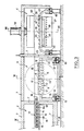
- la figure 1 est une vue en plan montrant l'emplacement des différentes unités de l'installation selon l'invention,
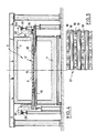
- la figure 2 est une vue en coupe longitudinale du four, des chambres d'aspiration, de retournement et de formage standard de l'installation,
- la figure 3 est une vue en coupe longitudinale des chambres d'aspiration, de retournement et de formage standard,
- la figure 4 est une vue en coupe selon le plan IV-IV de la figure 3,
- la figure 5 est une vue de dessous partielle du plateau aspirant,
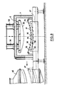
- la figure 6 est une vue en coupe suivant le plan VI-VI de la figure 3, montrant la chambre de retournement et la chambre de formage profond,
- la figure 7 est une vue en coupe selon le plan VII-VII de la figure 1,
- la figure 8 est une vue en coupe selon le plan VIII-VIII de la figure 3,
- la figure 9 est une vue de dessus partielle du plateau de retournement,
- la figure 10 est une vue de dessus de la partie inférieure de la chambre de formage standard.
- FIG. 1 is a plan view showing the location of the different units of the installation according to the invention,
- FIG. 2 is a view in longitudinal section of the furnace, of the suction, turning and standard forming chambers of the installation,
- FIG. 3 is a view in longitudinal section of the standard suction, turning and forming chambers,
- FIG. 4 is a sectional view along the plane IV-IV of FIG. 3,
- FIG. 5 is a partial bottom view of the suction plate,
- FIG. 6 is a sectional view along the plane VI-VI of FIG. 3, showing the turning chamber and the deep forming chamber,
- FIG. 7 is a sectional view along the plane VII-VII of FIG. 1,
- FIG. 8 is a sectional view along the plane VIII-VIII of FIG. 3,
- FIG. 9 is a partial top view of the turning table,
- Figure 10 is a top view of the bottom of the standard forming chamber.
L'installation telle que représentée sur les figures annexées pour le chauffage, le formage et la trempe de feuilles de verre, comprend un four 1 de chauffage des feuilles de verre, une chambre d'aspiration 2, une chambre de formage standard 4, une chambre de formage profond 5 et une chambre de trempe 6. Toutes ces chambres, à l'exception de celle de trempe, sont chauffées à une température suffisante pour maintenir les feuilles de verre à l'état plastique.The installation as shown in the appended figures for heating, forming and tempering glass sheets, comprises an
L'installation comprend également des moyens pour supporter les feuilles de verre et les déplacer horizontalement dans le four 1 et vers lesdites chambres 2 à 6.The installation also includes means for supporting the glass sheets and moving them horizontally in the
Conformément à l'invention, l'installation comprend en outre, entre le four 1 et les chambres de formage 4 et 5, une chambre de retournement 3 comportant des moyens pour retourner lesdites feuilles de verre.According to the invention, the installation further comprises, between the
Dans l'exemple représenté, le four 1, la chambre d'aspiration 2, la chambre de retournement 3 et la chambre de formage standard 4 sont alignées, tandis que la chambre de formage profond 5 et la chambre de trempe 6 sont situées à côté respectivement de la chambre de retournement 3 et la chambre de formage 4. Toutes les parois de ces chambres sont recouvertes par un revêtement réfractaire 7.In the example shown, the
Les moyens pour retourner les feuilles de verre 8 comprennent un plateau 9 monté en rotation autour d'un axe X-X′ dans la chambre de retournement 3. Ce plateau 9 est creux et comporte sur ses deux faces opposées 10, 11 une série d'ouvertures 12 réparties sur l'ensemble de ces faces (voir figures 3 et 9). L'intérieur du plateau 9 est relié par une conduite 9a (voir fig. 6) à des moyens d'aspiration telle qu'une turbine non représentée, pour créer une dépression à l'intérieur du plateau 9, suffisante pour plaquer une feuille de verre 8 sur la face 10 ou 11 pourvue d'ouvertures 12.The means for turning the
Par ailleurs, le plateau 9 pour retourner les feuilles de verre 8 est supporté par des moyens permettant de déplacer successivement les feuilles de verre retournées 8 vers la chambre de formage profond 5.Furthermore, the
A cet effet, (voir figures 3 et 6), les extrémités opposées de l'axe X-X′ de rotation du plateau 9 sont supportées par des montants 13 reposant par des galets 14 sur un chemin de roulement 15 qui s'étend entre la chambre de retournement 3 et la chambre de formage profond 5.To this end, (see Figures 3 and 6), the opposite ends of the axis XX ′ of rotation of the
Les figures 2 et 3 montrent qu'à l'intérieur du four 1 et de la chambre d'aspiration 2 est prévue une série de rouleaux parallèles et rotatifs 16 pour supporter les feuilles de verre 8 (voir figure 2) et les déplacer horizontalement vers la chambre de retournement 3 et/ou vers la chambre de formage standard 4 qui est alignée avec le four de chauffage 1.Figures 2 and 3 show that inside the
Selon l'invention, des moyens sont prévus en outre pour prélever les feuilles de verre 8 desdits rouleaux 16 pour les transférer vers la ou lesdites chambres 3, 4.According to the invention, means are also provided for removing the
Dans l'exemple représenté, lesdits moyens sont adaptés pour aspirer les feuilles de verre 8.In the example shown, said means are suitable for sucking up the
Ces moyens comprennent (voir figures 2, 3, 4 et 5) un plateau 17 aspirant mobile en translation au-dessus des rouleaux 16 supportant les feuilles de verre 8 et parallèlement à ces rouleaux 16. Ce plateau est lui-même pourvu de rouleaux 18 situés dans un plan parallèle à celui des rouleaux 16 supportant les feuilles de verre 8. Les rouleaux 18 du plateau 17 font saillie sous la face inférieure de ce plateau 17 et des ouvertures d'aspiration 19, sont ménagées entre les rouleaux 18 (voir figure 5).These means comprise (see FIGS. 2, 3, 4 and 5) a
L'intérieur du plateau 17 est relié à une conduite 17a (Fig. 2) elle-même reliée à une turbine d'aspiration non représentée.The interior of the
On voit en outre à la figure 4, que les rouleaux 18 portés par le plateau 17 sont entraînés en rotation par des poulies 20 montées à l'extrémité de leur axe 21 et reliées par un organe de transmission à un moteur non représenté.We also see in Figure 4, the
Par ailleurs, les extrémités des axes 21 des rouleaux 18 du plateau d'aspiration 17 sont soutenues par des bras 22 dont l'extrémité supérieure 22a repose sur un chemin de roulement 23 qui s'étend dans la chambre d'aspiration 2 et traverse les chambres de retournement 3 et la chambre de formage 4.Furthermore, the ends of the axes 21 of the
Par ailleurs, la longueur du plateau d'aspiration 17 mesurée dans la direction de son déplacement dépasse celle des feuilles de verre 8.Furthermore, the length of the
D'autre part, le plateau de retournement 9 des feuilles de verre 8 présente une face 10 destinée à recevoir les feuilles de verre 8, située dans le prolongement des rouleaux 16 supportant les feuilles de verre, de sorte que le plateau d'aspiration 17 peut passer au-dessus du plateau de retournement 9, comme le montre la figure 3.On the other hand, the turning
Comme indiqué précédemment, l'installation conforme à l'invention comprend une chambre de formage standard 4 et une chambre de formage profond 5. La chambre de formage standard 4 reçoit les feuilles de verre 8 dans la position qu'elles occupent sur les rouleaux 16 qui les supportent, tandis que la chambre de formage profond 5 reçoit les feuilles 8 en position retournée, grâce au plateau de retournement 9.As indicated above, the installation according to the invention comprises a
Les chambres de formage 4 et 5 comprennent chacune (voir figures 8 et 6) deux surfaces de formage 30, 31 ; 32, 33 mobiles l'une vers l'autre. L'une de ces surfaces est convexe et l'autre est concave.The forming
Dans le cas de la chambre de formage standard 4 (voir figure 8), la surface de formage concave 31 est mobile horizontalement vers la chambre de trempe 6 et la surface de formage convexe 30 est mobile verticalement vers cette dernière, grâce à des mécanismes de commande 34.In the case of the standard forming chamber 4 (see FIG. 8), the concave forming
Dans le cas de la chambre de formage profond 5 (voir figure 6), la surface de formage concave 32 est mobile horizontalement vers la chambre de trempe 6 et la surface de formage convexe 33 est mobile verticalement vers cette dernière (voir flèche F sur la figure 6).In the case of the deep forming chamber 5 (see FIG. 6), the concave forming
Par ailleurs, dans la chambre de formage standard 4, la surface de formage concave 31 est située à la partie inférieure de la chambre et comporte (voir également la figure 10) un anneau creux 35 destiné à recevoir la feuille 8 à former et dont le contour correspond à celui de la feuille à l'état formé. Cet anneau 35 présente sur sa surface 31 destinée à recevoir une feuille de verre 8, une série de trous 36 communiquant avec l'intérieur de cet anneau 35 qui est relié par une conduite 35a (voir figure 10) à des moyens d'aspiration (non représentés) pour créer une dépression à l'intérieur de cet anneau 35.Furthermore, in the
Par ailleurs, sous l'anneau 35 est disposé (voir figures 8 et 10) un corps 37 présentant une série de trous 38 reliés à des moyens (non représentés) pour souffler de l'air chaud sous une feuille de verre 8 reposant sur l'anneau 35.Furthermore, under the
Dans la chambre de formage profond 5 (voir figure 6) la surface de formage concave mobile horizontalement 32 est située à la partie supérieure de la chambre et comporte un anneau creux 39 destiné à recevoir la feuille à former. Le contour de cet anneau 39 correspond à celui de la feuille à l'état formé et présente sur sa surface 32 destinée à recevoir la feuille, une série de trous 40 communiquant avec l'intérieur de cet anneau 39 et avec des moyens d'aspiration (non représentés) pour créer une dépression en son intérieur.In the deep forming chamber 5 (see FIG. 6) the horizontally movable concave forming
D'autre part, la surface de formage convexe et mobile verticalement 33 située à la partie inférieure de la chambre de formage profond 5 comporte un rebord périphérique destiné à correspondre au contour de la feuille à l'état formé qui entoure une cavité 50 présentant une série de trous 41 reliés à des moyens (non représentés) pour souffler de l'air chaud sous la feuille de verre, de façon à éviter l'affaissement de la feuille de verre.On the other hand, the convex and vertically movable forming
On va maintenant décrire le fonctionnement de l'installation conforme à la présente invention.We will now describe the operation of the installation according to the present invention.
Les feuilles de verre plates 8 reposant sur les rouleaux 16 sont d'abord chauffées dans le four 1 à une température comprise entre 600 et 700°C pour les rendre aptes au formage ultérieur.The
Les feuilles chauffées sont ensuite acheminées par les rouleaux rotatifs 16 vers la chambre d'aspiration 2 qui est également chauffée à une certaine température pour éviter tout refroidissement des feuilles de verre. Le plateau 17 d'aspiration est positionné au-dessus d'une feuille de verre 8. A la mise en route des moyens d'aspiration, la feuille de verre est aspirée vers le plateau 17 situé à la proximité immédiate de cette feuille, de sorte que celle-ci vient légèrement en contact contre les rouleaux 18 du plateau aspirant 17.The heated sheets are then conveyed by the
Lorsque la feuille de verre 8 doit subir un formage standard, le plateau 17 est déplacé sur son chemin de roulement 23 directement vers la chambre 4 de formage standard.When the
Lors de ce déplacement, le plateau 17 passe au-dessus du plateau 9 de retournement.During this movement, the
Par ailleurs, lors de ce déplacement, la feuille de verre 8 plaquée sous le plateau 17 d'aspiration subit une translation par rapport à ce plateau, par rotation des rouleaux 18 contre lesquels la feuille 8 est en contact, ce qui a pour effet d'éviter le marquage de la feuille de verre par contact avec ces rouleaux 18 et de permettre le positionnement de la feuille de verre 8 au-dessus de l'anneau 35 de la chambre de formage 4. Bien entendu, la vitesse de rotation des rouleaux 18 sera relativement réduite afin que la vitesse de déplacement de la feuille 8 par rapport au plateau soit inférieure à la vitesse de déplacement de ce plateau 17.Furthermore, during this movement, the
A ce sujet, il convient bien entendu que la longueur du plateau 17 soit assez nettement supérieure à celle des feuilles à transporter.In this regard, it should of course be that the length of the
En fin de course, le plateau 17 amène la feuille de verre 8 juste au-dessus de l'anneau 35 constituant la surface de formage inférieure de la chambre 4.At the end of the race, the
Il suffit ensuite de couper l'aspiration pour libérer la feuille de verre du plateau 17 pour qu'elle se dépose sur l'anneau 35.It then suffices to cut the suction to release the glass sheet from the
Dès le retour du plateau 17, on commande la descente de la surface de formage convexe 30 pour adapter le profil de formage de la feuille de verre à celui des surfaces convexe 30 et concave 31.As soon as the
En même temps, on envoie des jets d'air chaud, par les trous 38, vers la surface inférieure de la feuille 8 pour maintenir celle-ci à la température voulue et pour éviter qu'elle se déforme par gravité à travers l'anneau 35.At the same time, jets of hot air are sent, through the
Lorsqu'on veut procéder à un formage profond, le plateau 17 situé dans la chambre d'aspiration 2 et maintenant sous lui, une feuille de verre 8 est déplacé vers la chambre de retournement 3.When a deep forming is to be carried out, the
Lorsque la feuille de verre 8 est située exactement au-dessus du plateau 9 de retournement, l'aspiration est interrompue de façon que la feuille de verre 8 puisse se déposer sur la face supérieure 10 du plateau 9. Une dépression est alors réalisée à l'intérieur du plateau 9 de façon à plaquer par aspiration la feuille 8 sur le dessus de ce plateau.When the
On commande alors la rotation du plateau 9 autour de son axe X-X′ de façon à le retourner de 180° et que la feuille de verre 8 soit située sous le plateau. La feuille de verre 8 reste plaquée sous le plateau du fait de l'aspiration. On peut alors déplacer le plateau 9 le long des chemins de roulement 15 vers la chambre de formage profond 5.The rotation of the
Lorsque le plateau 9 est situé entre les surfaces de formage 32 et 33 (voir position en traits mixtes sur la figure 6), l'aspiration est coupée et la feuille de verre 8 se dépose sur la surface de formage inférieure et convexe 33. Le plateau de retournement 9 est alors ramené vers la chambre de retournement 3 pour recevoir après rotation de 180° une nouvelle feuille de verre 8.When the
Dès que le plateau 9 a quitté la chambre de formage 5, la surface de formage 33 sur laquelle repose la feuille de verre 8 se déplace vers le haut pour appliquer la feuille contre l'anneau 39 et former ainsi cette feuille suivant le profil des surfaces 33 et 32.As soon as the
Pendant cette opération, des jets d'air chaud sont envoyés vers la feuille 8 par les trous 41 pour éviter l'affaissement de cette feuille, tandis qu'une dépression est réalisée dans l'anneau 39 afin de plaquer la périphérie de la feuille de verre 8 contre la surface 32 de l'anneau 39 et ainsi éviter tout glissement latéral de la feuille 8.During this operation, jets of hot air are sent to the
Après formage des feuilles de verre 8, soit dans !a chambre de formage standard 4, soit dans la chambre de formage profond 5, les feuilles de verre 8 sont déplacées successivement vers la chambre de trempe 6.After the
Lorsqu'une feuille de verre 8 a été formée dans la chambre standard 4, elle est déplacée vers la chambre de trempe 6, le long des chemins de roulement 42 (voir figure 2) sur lesquels prend appui le bâti 43 qui supporte l'anneau 35 qui supporte la feuille de verre formée 8.When a
Lorsqu'une feuille de verre 8 a été formée dans la chambre de formage profond 4, elle est déplacée vers la chambre de trempe 6, le long des chemins de roulement 44 (voir figure 6) sur lesquels prend appui le bâti 45 auquel est suspendu l'anneau 39 qui maintient par aspiration la feuille de verre 8 ayant subi un formage profond.When a
Lors de la trempe, la feuille de verre 8 est placée (voir figure 7) entre deux corps 46, 47 présentant des canaux verticaux 48, 49 qui envoient de part et d'autre de la feuille de verre 8 des jets gazeux destinés à la trempe de la feuille de verre 8.During tempering, the
Bien entendu, l'invention n'est pas limitée à l'exemple de réalisation que l'on vient de décrire et on peut apporter à celui-ci de nombreuses modifications sans sortir du cadre de l'invention.Of course, the invention is not limited to the embodiment which has just been described and many modifications can be made to it without departing from the scope of the invention.
Ainsi, toutes les chambres pourraient être alignées les unes à la suite des autres.Thus, all the rooms could be aligned one after the other.
Claims (17)
Applications Claiming Priority (2)
| Application Number | Priority Date | Filing Date | Title |
|---|---|---|---|
| FR9004097A FR2660302B1 (en) | 1990-03-30 | 1990-03-30 | INSTALLATION FOR HEATING, FORMING AND TEMPERING GLASS SHEETS. |
| FR9004097 | 1990-03-30 |
Publications (1)
| Publication Number | Publication Date |
|---|---|
| EP0451010A1 true EP0451010A1 (en) | 1991-10-09 |
Family
ID=9395290
Family Applications (1)
| Application Number | Title | Priority Date | Filing Date |
|---|---|---|---|
| EP91400787A Withdrawn EP0451010A1 (en) | 1990-03-30 | 1991-03-22 | Apparatus for heating, forming and tempering glass sheets |
Country Status (6)
| Country | Link |
|---|---|
| US (1) | US5160524A (en) |
| EP (1) | EP0451010A1 (en) |
| DE (1) | DE451010T1 (en) |
| ES (1) | ES2026439T1 (en) |
| FR (1) | FR2660302B1 (en) |
| GR (1) | GR910300138T1 (en) |
Cited By (3)
| Publication number | Priority date | Publication date | Assignee | Title |
|---|---|---|---|---|
| EP0494823A2 (en) * | 1991-01-09 | 1992-07-15 | Saint-Gobain Vitrage International | Method and apparatus for treating hot glass sheets |
| EP0520886A1 (en) * | 1991-06-27 | 1992-12-30 | Saint-Gobain Vitrage International | Method and apparatus for bending a sheet of glass |
| KR101169658B1 (en) * | 2002-11-08 | 2012-08-03 | 슈프레스타 엘엘씨 | Epoxy resin composition containing reactive flame retardant phosphonate oligomer and filler |
Families Citing this family (4)
| Publication number | Priority date | Publication date | Assignee | Title |
|---|---|---|---|---|
| DE4215285C1 (en) * | 1992-05-09 | 1993-08-19 | Vegla Vereinigte Glaswerke Gmbh, 5100 Aachen, De | |
| US5320661A (en) * | 1992-07-02 | 1994-06-14 | Ppg Industries, Inc. | Method and apparatus of bending glass sheets |
| JP4027266B2 (en) * | 2003-05-23 | 2007-12-26 | Hoya株式会社 | Method for slowly cooling glass article, method for heating glass article, method for producing glass molded article, and heat treatment apparatus |
| CN108793702B (en) * | 2018-07-08 | 2021-11-02 | 威海烟华安全玻璃有限公司 | Air-cooled quenching device for glass production |
Citations (5)
| Publication number | Priority date | Publication date | Assignee | Title |
|---|---|---|---|---|
| US3665730A (en) * | 1970-06-11 | 1972-05-30 | Frederick D Linzer | Apparatus for simultaneously supporting, cooling and shaping glass sheet and the like |
| US3680677A (en) * | 1969-09-19 | 1972-08-01 | Pilkington Brothers Ltd | Conveying of glass sheets |
| US4711653A (en) * | 1986-12-29 | 1987-12-08 | Ppg Industries, Inc. | Innovative press bending of thermoplastic sheets |
| EP0267119A1 (en) * | 1986-11-06 | 1988-05-11 | Saint-Gobain Vitrage International | Bending/tempering apparatus in the production of flat or bent glass sheets |
| EP0299869A1 (en) * | 1987-07-15 | 1989-01-18 | Saint-Gobain Vitrage International | Bending of glass sheets |
Family Cites Families (3)
| Publication number | Priority date | Publication date | Assignee | Title |
|---|---|---|---|---|
| DE3407173C1 (en) * | 1984-02-28 | 1985-01-03 | Mannesmann AG, 4000 Düsseldorf | Plant for the production of strongly curved glass panes |
| JPS6345138A (en) * | 1986-08-08 | 1988-02-26 | Asahi Glass Co Ltd | Bending method for glass plate |
| DE68905703T2 (en) * | 1988-08-03 | 1993-07-08 | Nippon Sheet Glass Co Ltd | DEVICE FOR BENDING GLASS PANES. |
-
1990
- 1990-03-30 FR FR9004097A patent/FR2660302B1/en not_active Expired - Fee Related
-
1991
- 1991-03-18 US US07/673,179 patent/US5160524A/en not_active Expired - Fee Related
- 1991-03-22 EP EP91400787A patent/EP0451010A1/en not_active Withdrawn
- 1991-03-22 DE DE199191400787T patent/DE451010T1/en active Pending
- 1991-03-22 ES ES199191400787T patent/ES2026439T1/en active Pending
-
1992
- 1992-06-30 GR GR91300138T patent/GR910300138T1/en unknown
Patent Citations (5)
| Publication number | Priority date | Publication date | Assignee | Title |
|---|---|---|---|---|
| US3680677A (en) * | 1969-09-19 | 1972-08-01 | Pilkington Brothers Ltd | Conveying of glass sheets |
| US3665730A (en) * | 1970-06-11 | 1972-05-30 | Frederick D Linzer | Apparatus for simultaneously supporting, cooling and shaping glass sheet and the like |
| EP0267119A1 (en) * | 1986-11-06 | 1988-05-11 | Saint-Gobain Vitrage International | Bending/tempering apparatus in the production of flat or bent glass sheets |
| US4711653A (en) * | 1986-12-29 | 1987-12-08 | Ppg Industries, Inc. | Innovative press bending of thermoplastic sheets |
| EP0299869A1 (en) * | 1987-07-15 | 1989-01-18 | Saint-Gobain Vitrage International | Bending of glass sheets |
Non-Patent Citations (1)
| Title |
|---|
| PATENT ABSTRACTS OF JAPAN, vol. 12, no. 258 (C-513)[3105] 20 juillet 1988; & JP-A-63 045 138 (ASAHI GLASS CO. LTD.) 26 février 1988, * |
Cited By (6)
| Publication number | Priority date | Publication date | Assignee | Title |
|---|---|---|---|---|
| EP0494823A2 (en) * | 1991-01-09 | 1992-07-15 | Saint-Gobain Vitrage International | Method and apparatus for treating hot glass sheets |
| EP0494823A3 (en) * | 1991-01-09 | 1993-08-04 | Saint-Gobain Vitrage International | Method and apparatus for treating hot glass sheets |
| EP0520886A1 (en) * | 1991-06-27 | 1992-12-30 | Saint-Gobain Vitrage International | Method and apparatus for bending a sheet of glass |
| FR2678261A1 (en) * | 1991-06-27 | 1992-12-31 | Saint Gobain Vitrage Int | METHOD AND DEVICE FOR BOMBING A GLASS SHEET |
| US5372624A (en) * | 1991-06-27 | 1994-12-13 | Saint-Gobain Vitrage International | Process and apparatus for bending a glass sheet |
| KR101169658B1 (en) * | 2002-11-08 | 2012-08-03 | 슈프레스타 엘엘씨 | Epoxy resin composition containing reactive flame retardant phosphonate oligomer and filler |
Also Published As
| Publication number | Publication date |
|---|---|
| FR2660302B1 (en) | 1992-08-07 |
| US5160524A (en) | 1992-11-03 |
| FR2660302A1 (en) | 1991-10-04 |
| GR910300138T1 (en) | 1992-06-30 |
| ES2026439T1 (en) | 1992-05-01 |
| DE451010T1 (en) | 1992-02-06 |
Similar Documents
| Publication | Publication Date | Title |
|---|---|---|
| EP0290346B1 (en) | Method and apparatus for bending glass plates | |
| EP0556103B1 (en) | Apparatus for bending windscreens | |
| EP0241355B1 (en) | Apparatus for bending glass sheets | |
| CA2031748C (en) | Glazing manufacturing line with multiple workstations | |
| FR2612509A1 (en) | METHOD AND APPARATUS FOR CAMBING SHEETS, ESPECIALLY GLASS | |
| CA2019486C (en) | Process and apparatus for effecting curving and tempering by contact | |
| FR2609017A1 (en) | APPARATUS AND METHOD FOR CAMBING SHEETS, IN PARTICULAR GLASS | |
| EP1611064A2 (en) | Method for crowning sheets of glass by pressing and suction | |
| WO2006075117A1 (en) | Glass-bending and cooling method and device comprising two support trains | |
| EP1301444B1 (en) | Method and device for bending a glass sheet | |
| EP0474531B1 (en) | Method and apparatus for bending glass sheets | |
| FR2757149A1 (en) | Multi=layered sheet material shaping system | |
| WO2005102945A1 (en) | Device and method for cambering a glass sheet | |
| EP0451010A1 (en) | Apparatus for heating, forming and tempering glass sheets | |
| EP0389315B1 (en) | Positioning of a glass sheet opposite to devices for bending and/or another thermal treatment | |
| FR2546503A1 (en) | MULTI-CHAMBER VACUUM SUPPORT, USED FOR FORMING GLASS SHEETS, WITH MEANS FOR ISOLATING NEIGHBORING VACUUM CHAMBERS | |
| FR2609283A1 (en) | APPARATUS AND METHOD FOR PROFILING A SOFT SHEET OF GLASS BY HEATING | |
| BE1000065A6 (en) | Method and apparatus for bending glass sheets. | |
| EP0373992A1 (en) | Process and apparatus for producing convex tempered car windows | |
| EP0299869B1 (en) | Bending of glass sheets | |
| FR2516502A1 (en) | METHOD AND APPARATUS FOR EXTRACTING HANGED AND TEMPERED GLASS SHEETS FROM A COOLING STATION | |
| EP0274295B1 (en) | Method and apparatus for automatically assembling layered-glass panes | |
| EP0409695B1 (en) | Method and apparatus for manufacturing curved and/or enamelled sheets of glass | |
| EP0463971A2 (en) | Method and apparatus for bending and tempering sheets of glass | |
| FR2546504A1 (en) | METHOD FOR COOLING A VACUUM-PRESSURE MEDIUM |
Legal Events
| Date | Code | Title | Description |
|---|---|---|---|
| PUAI | Public reference made under article 153(3) epc to a published international application that has entered the european phase |
Free format text: ORIGINAL CODE: 0009012 |
|
| 17P | Request for examination filed |
Effective date: 19910327 |
|
| AK | Designated contracting states |
Kind code of ref document: A1 Designated state(s): AT BE CH DE DK ES GB GR IT LI LU NL SE |
|
| TCAT | At: translation of patent claims filed | ||
| ITCL | It: translation for ep claims filed |
Representative=s name: BARZANO' E ZANARDO ROMA S.P.A. |
|
| GBC | Gb: translation of claims filed (gb section 78(7)/1977) | ||
| TCNL | Nl: translation of patent claims filed | ||
| DET | De: translation of patent claims | ||
| REG | Reference to a national code |
Ref country code: ES Ref legal event code: BA2A Ref document number: 2026439 Country of ref document: ES Kind code of ref document: T1 |
|
| 17Q | First examination report despatched |
Effective date: 19930510 |
|
| STAA | Information on the status of an ep patent application or granted ep patent |
Free format text: STATUS: THE APPLICATION IS DEEMED TO BE WITHDRAWN |
|
| 18D | Application deemed to be withdrawn |
Effective date: 19940705 |