EP0450872B1 - Endothermischer Reaktionsapparat - Google Patents
Endothermischer Reaktionsapparat Download PDFInfo
- Publication number
- EP0450872B1 EP0450872B1 EP91302767A EP91302767A EP0450872B1 EP 0450872 B1 EP0450872 B1 EP 0450872B1 EP 91302767 A EP91302767 A EP 91302767A EP 91302767 A EP91302767 A EP 91302767A EP 0450872 B1 EP0450872 B1 EP 0450872B1
- Authority
- EP
- European Patent Office
- Prior art keywords
- tube
- reaction vessel
- fuel
- reaction
- combustion tube
- Prior art date
- Legal status (The legal status is an assumption and is not a legal conclusion. Google has not performed a legal analysis and makes no representation as to the accuracy of the status listed.)
- Expired - Lifetime
Links
Images


Classifications
-
- B—PERFORMING OPERATIONS; TRANSPORTING
- B01—PHYSICAL OR CHEMICAL PROCESSES OR APPARATUS IN GENERAL
- B01J—CHEMICAL OR PHYSICAL PROCESSES, e.g. CATALYSIS OR COLLOID CHEMISTRY; THEIR RELEVANT APPARATUS
- B01J8/00—Chemical or physical processes in general, conducted in the presence of fluids and solid particles; Apparatus for such processes
- B01J8/02—Chemical or physical processes in general, conducted in the presence of fluids and solid particles; Apparatus for such processes with stationary particles, e.g. in fixed beds
- B01J8/04—Chemical or physical processes in general, conducted in the presence of fluids and solid particles; Apparatus for such processes with stationary particles, e.g. in fixed beds the fluid passing successively through two or more beds
- B01J8/0446—Chemical or physical processes in general, conducted in the presence of fluids and solid particles; Apparatus for such processes with stationary particles, e.g. in fixed beds the fluid passing successively through two or more beds the flow within the beds being predominantly vertical
- B01J8/0449—Chemical or physical processes in general, conducted in the presence of fluids and solid particles; Apparatus for such processes with stationary particles, e.g. in fixed beds the fluid passing successively through two or more beds the flow within the beds being predominantly vertical in two or more cylindrical beds
- B01J8/0453—Chemical or physical processes in general, conducted in the presence of fluids and solid particles; Apparatus for such processes with stationary particles, e.g. in fixed beds the fluid passing successively through two or more beds the flow within the beds being predominantly vertical in two or more cylindrical beds the beds being superimposed one above the other
-
- B—PERFORMING OPERATIONS; TRANSPORTING
- B01—PHYSICAL OR CHEMICAL PROCESSES OR APPARATUS IN GENERAL
- B01J—CHEMICAL OR PHYSICAL PROCESSES, e.g. CATALYSIS OR COLLOID CHEMISTRY; THEIR RELEVANT APPARATUS
- B01J19/00—Chemical, physical or physico-chemical processes in general; Their relevant apparatus
- B01J19/02—Apparatus characterised by being constructed of material selected for its chemically-resistant properties
-
- B—PERFORMING OPERATIONS; TRANSPORTING
- B01—PHYSICAL OR CHEMICAL PROCESSES OR APPARATUS IN GENERAL
- B01J—CHEMICAL OR PHYSICAL PROCESSES, e.g. CATALYSIS OR COLLOID CHEMISTRY; THEIR RELEVANT APPARATUS
- B01J8/00—Chemical or physical processes in general, conducted in the presence of fluids and solid particles; Apparatus for such processes
- B01J8/008—Details of the reactor or of the particulate material; Processes to increase or to retard the rate of reaction
-
- B—PERFORMING OPERATIONS; TRANSPORTING
- B01—PHYSICAL OR CHEMICAL PROCESSES OR APPARATUS IN GENERAL
- B01J—CHEMICAL OR PHYSICAL PROCESSES, e.g. CATALYSIS OR COLLOID CHEMISTRY; THEIR RELEVANT APPARATUS
- B01J8/00—Chemical or physical processes in general, conducted in the presence of fluids and solid particles; Apparatus for such processes
- B01J8/02—Chemical or physical processes in general, conducted in the presence of fluids and solid particles; Apparatus for such processes with stationary particles, e.g. in fixed beds
- B01J8/0242—Chemical or physical processes in general, conducted in the presence of fluids and solid particles; Apparatus for such processes with stationary particles, e.g. in fixed beds the fluid flow within the bed being predominantly vertical
- B01J8/025—Chemical or physical processes in general, conducted in the presence of fluids and solid particles; Apparatus for such processes with stationary particles, e.g. in fixed beds the fluid flow within the bed being predominantly vertical in a cylindrical shaped bed
-
- B—PERFORMING OPERATIONS; TRANSPORTING
- B01—PHYSICAL OR CHEMICAL PROCESSES OR APPARATUS IN GENERAL
- B01J—CHEMICAL OR PHYSICAL PROCESSES, e.g. CATALYSIS OR COLLOID CHEMISTRY; THEIR RELEVANT APPARATUS
- B01J8/00—Chemical or physical processes in general, conducted in the presence of fluids and solid particles; Apparatus for such processes
- B01J8/02—Chemical or physical processes in general, conducted in the presence of fluids and solid particles; Apparatus for such processes with stationary particles, e.g. in fixed beds
- B01J8/0285—Heating or cooling the reactor
-
- B—PERFORMING OPERATIONS; TRANSPORTING
- B01—PHYSICAL OR CHEMICAL PROCESSES OR APPARATUS IN GENERAL
- B01J—CHEMICAL OR PHYSICAL PROCESSES, e.g. CATALYSIS OR COLLOID CHEMISTRY; THEIR RELEVANT APPARATUS
- B01J8/00—Chemical or physical processes in general, conducted in the presence of fluids and solid particles; Apparatus for such processes
- B01J8/02—Chemical or physical processes in general, conducted in the presence of fluids and solid particles; Apparatus for such processes with stationary particles, e.g. in fixed beds
- B01J8/06—Chemical or physical processes in general, conducted in the presence of fluids and solid particles; Apparatus for such processes with stationary particles, e.g. in fixed beds in tube reactors; the solid particles being arranged in tubes
- B01J8/062—Chemical or physical processes in general, conducted in the presence of fluids and solid particles; Apparatus for such processes with stationary particles, e.g. in fixed beds in tube reactors; the solid particles being arranged in tubes being installed in a furnace
-
- C—CHEMISTRY; METALLURGY
- C01—INORGANIC CHEMISTRY
- C01B—NON-METALLIC ELEMENTS; COMPOUNDS THEREOF; METALLOIDS OR COMPOUNDS THEREOF NOT COVERED BY SUBCLASS C01C
- C01B3/00—Hydrogen; Gaseous mixtures containing hydrogen; Separation of hydrogen from mixtures containing it; Purification of hydrogen
- C01B3/02—Production of hydrogen or of gaseous mixtures containing a substantial proportion of hydrogen
- C01B3/32—Production of hydrogen or of gaseous mixtures containing a substantial proportion of hydrogen by reaction of gaseous or liquid organic compounds with gasifying agents, e.g. water, carbon dioxide, air
- C01B3/34—Production of hydrogen or of gaseous mixtures containing a substantial proportion of hydrogen by reaction of gaseous or liquid organic compounds with gasifying agents, e.g. water, carbon dioxide, air by reaction of hydrocarbons with gasifying agents
- C01B3/38—Production of hydrogen or of gaseous mixtures containing a substantial proportion of hydrogen by reaction of gaseous or liquid organic compounds with gasifying agents, e.g. water, carbon dioxide, air by reaction of hydrocarbons with gasifying agents using catalysts
- C01B3/384—Production of hydrogen or of gaseous mixtures containing a substantial proportion of hydrogen by reaction of gaseous or liquid organic compounds with gasifying agents, e.g. water, carbon dioxide, air by reaction of hydrocarbons with gasifying agents using catalysts the catalyst being continuously externally heated
-
- B—PERFORMING OPERATIONS; TRANSPORTING
- B01—PHYSICAL OR CHEMICAL PROCESSES OR APPARATUS IN GENERAL
- B01J—CHEMICAL OR PHYSICAL PROCESSES, e.g. CATALYSIS OR COLLOID CHEMISTRY; THEIR RELEVANT APPARATUS
- B01J2208/00—Processes carried out in the presence of solid particles; Reactors therefor
- B01J2208/00008—Controlling the process
- B01J2208/00017—Controlling the temperature
- B01J2208/00106—Controlling the temperature by indirect heat exchange
- B01J2208/00168—Controlling the temperature by indirect heat exchange with heat exchange elements outside the bed of solid particles
- B01J2208/00203—Coils
-
- B—PERFORMING OPERATIONS; TRANSPORTING
- B01—PHYSICAL OR CHEMICAL PROCESSES OR APPARATUS IN GENERAL
- B01J—CHEMICAL OR PHYSICAL PROCESSES, e.g. CATALYSIS OR COLLOID CHEMISTRY; THEIR RELEVANT APPARATUS
- B01J2208/00—Processes carried out in the presence of solid particles; Reactors therefor
- B01J2208/00008—Controlling the process
- B01J2208/00017—Controlling the temperature
- B01J2208/00389—Controlling the temperature using electric heating or cooling elements
- B01J2208/00407—Controlling the temperature using electric heating or cooling elements outside the reactor bed
-
- B—PERFORMING OPERATIONS; TRANSPORTING
- B01—PHYSICAL OR CHEMICAL PROCESSES OR APPARATUS IN GENERAL
- B01J—CHEMICAL OR PHYSICAL PROCESSES, e.g. CATALYSIS OR COLLOID CHEMISTRY; THEIR RELEVANT APPARATUS
- B01J2208/00—Processes carried out in the presence of solid particles; Reactors therefor
- B01J2208/00008—Controlling the process
- B01J2208/00017—Controlling the temperature
- B01J2208/00477—Controlling the temperature by thermal insulation means
- B01J2208/00495—Controlling the temperature by thermal insulation means using insulating materials or refractories
-
- B—PERFORMING OPERATIONS; TRANSPORTING
- B01—PHYSICAL OR CHEMICAL PROCESSES OR APPARATUS IN GENERAL
- B01J—CHEMICAL OR PHYSICAL PROCESSES, e.g. CATALYSIS OR COLLOID CHEMISTRY; THEIR RELEVANT APPARATUS
- B01J2208/00—Processes carried out in the presence of solid particles; Reactors therefor
- B01J2208/00008—Controlling the process
- B01J2208/00017—Controlling the temperature
- B01J2208/00504—Controlling the temperature by means of a burner
-
- B—PERFORMING OPERATIONS; TRANSPORTING
- B01—PHYSICAL OR CHEMICAL PROCESSES OR APPARATUS IN GENERAL
- B01J—CHEMICAL OR PHYSICAL PROCESSES, e.g. CATALYSIS OR COLLOID CHEMISTRY; THEIR RELEVANT APPARATUS
- B01J2208/00—Processes carried out in the presence of solid particles; Reactors therefor
- B01J2208/00008—Controlling the process
- B01J2208/00017—Controlling the temperature
- B01J2208/00513—Controlling the temperature using inert heat absorbing solids in the bed
-
- B—PERFORMING OPERATIONS; TRANSPORTING
- B01—PHYSICAL OR CHEMICAL PROCESSES OR APPARATUS IN GENERAL
- B01J—CHEMICAL OR PHYSICAL PROCESSES, e.g. CATALYSIS OR COLLOID CHEMISTRY; THEIR RELEVANT APPARATUS
- B01J2208/00—Processes carried out in the presence of solid particles; Reactors therefor
- B01J2208/00008—Controlling the process
- B01J2208/00716—Means for reactor start-up
-
- C—CHEMISTRY; METALLURGY
- C01—INORGANIC CHEMISTRY
- C01B—NON-METALLIC ELEMENTS; COMPOUNDS THEREOF; METALLOIDS OR COMPOUNDS THEREOF NOT COVERED BY SUBCLASS C01C
- C01B2203/00—Integrated processes for the production of hydrogen or synthesis gas
- C01B2203/02—Processes for making hydrogen or synthesis gas
- C01B2203/0205—Processes for making hydrogen or synthesis gas containing a reforming step
- C01B2203/0227—Processes for making hydrogen or synthesis gas containing a reforming step containing a catalytic reforming step
- C01B2203/0233—Processes for making hydrogen or synthesis gas containing a reforming step containing a catalytic reforming step the reforming step being a steam reforming step
-
- C—CHEMISTRY; METALLURGY
- C01—INORGANIC CHEMISTRY
- C01B—NON-METALLIC ELEMENTS; COMPOUNDS THEREOF; METALLOIDS OR COMPOUNDS THEREOF NOT COVERED BY SUBCLASS C01C
- C01B2203/00—Integrated processes for the production of hydrogen or synthesis gas
- C01B2203/02—Processes for making hydrogen or synthesis gas
- C01B2203/0266—Processes for making hydrogen or synthesis gas containing a decomposition step
- C01B2203/0277—Processes for making hydrogen or synthesis gas containing a decomposition step containing a catalytic decomposition step
-
- C—CHEMISTRY; METALLURGY
- C01—INORGANIC CHEMISTRY
- C01B—NON-METALLIC ELEMENTS; COMPOUNDS THEREOF; METALLOIDS OR COMPOUNDS THEREOF NOT COVERED BY SUBCLASS C01C
- C01B2203/00—Integrated processes for the production of hydrogen or synthesis gas
- C01B2203/02—Processes for making hydrogen or synthesis gas
- C01B2203/0283—Processes for making hydrogen or synthesis gas containing a CO-shift step, i.e. a water gas shift step
-
- C—CHEMISTRY; METALLURGY
- C01—INORGANIC CHEMISTRY
- C01B—NON-METALLIC ELEMENTS; COMPOUNDS THEREOF; METALLOIDS OR COMPOUNDS THEREOF NOT COVERED BY SUBCLASS C01C
- C01B2203/00—Integrated processes for the production of hydrogen or synthesis gas
- C01B2203/06—Integration with other chemical processes
- C01B2203/061—Methanol production
-
- C—CHEMISTRY; METALLURGY
- C01—INORGANIC CHEMISTRY
- C01B—NON-METALLIC ELEMENTS; COMPOUNDS THEREOF; METALLOIDS OR COMPOUNDS THEREOF NOT COVERED BY SUBCLASS C01C
- C01B2203/00—Integrated processes for the production of hydrogen or synthesis gas
- C01B2203/06—Integration with other chemical processes
- C01B2203/062—Hydrocarbon production, e.g. Fischer-Tropsch process
-
- C—CHEMISTRY; METALLURGY
- C01—INORGANIC CHEMISTRY
- C01B—NON-METALLIC ELEMENTS; COMPOUNDS THEREOF; METALLOIDS OR COMPOUNDS THEREOF NOT COVERED BY SUBCLASS C01C
- C01B2203/00—Integrated processes for the production of hydrogen or synthesis gas
- C01B2203/06—Integration with other chemical processes
- C01B2203/068—Ammonia synthesis
-
- C—CHEMISTRY; METALLURGY
- C01—INORGANIC CHEMISTRY
- C01B—NON-METALLIC ELEMENTS; COMPOUNDS THEREOF; METALLOIDS OR COMPOUNDS THEREOF NOT COVERED BY SUBCLASS C01C
- C01B2203/00—Integrated processes for the production of hydrogen or synthesis gas
- C01B2203/08—Methods of heating or cooling
- C01B2203/0805—Methods of heating the process for making hydrogen or synthesis gas
- C01B2203/0811—Methods of heating the process for making hydrogen or synthesis gas by combustion of fuel
- C01B2203/0816—Heating by flames
-
- C—CHEMISTRY; METALLURGY
- C01—INORGANIC CHEMISTRY
- C01B—NON-METALLIC ELEMENTS; COMPOUNDS THEREOF; METALLOIDS OR COMPOUNDS THEREOF NOT COVERED BY SUBCLASS C01C
- C01B2203/00—Integrated processes for the production of hydrogen or synthesis gas
- C01B2203/08—Methods of heating or cooling
- C01B2203/0805—Methods of heating the process for making hydrogen or synthesis gas
- C01B2203/0838—Methods of heating the process for making hydrogen or synthesis gas by heat exchange with exothermic reactions, other than by combustion of fuel
- C01B2203/0844—Methods of heating the process for making hydrogen or synthesis gas by heat exchange with exothermic reactions, other than by combustion of fuel the non-combustive exothermic reaction being another reforming reaction as defined in groups C01B2203/02 - C01B2203/0294
-
- C—CHEMISTRY; METALLURGY
- C01—INORGANIC CHEMISTRY
- C01B—NON-METALLIC ELEMENTS; COMPOUNDS THEREOF; METALLOIDS OR COMPOUNDS THEREOF NOT COVERED BY SUBCLASS C01C
- C01B2203/00—Integrated processes for the production of hydrogen or synthesis gas
- C01B2203/08—Methods of heating or cooling
- C01B2203/0805—Methods of heating the process for making hydrogen or synthesis gas
- C01B2203/085—Methods of heating the process for making hydrogen or synthesis gas by electric heating
-
- C—CHEMISTRY; METALLURGY
- C01—INORGANIC CHEMISTRY
- C01B—NON-METALLIC ELEMENTS; COMPOUNDS THEREOF; METALLOIDS OR COMPOUNDS THEREOF NOT COVERED BY SUBCLASS C01C
- C01B2203/00—Integrated processes for the production of hydrogen or synthesis gas
- C01B2203/08—Methods of heating or cooling
- C01B2203/0805—Methods of heating the process for making hydrogen or synthesis gas
- C01B2203/0866—Methods of heating the process for making hydrogen or synthesis gas by combination of different heating methods
-
- C—CHEMISTRY; METALLURGY
- C01—INORGANIC CHEMISTRY
- C01B—NON-METALLIC ELEMENTS; COMPOUNDS THEREOF; METALLOIDS OR COMPOUNDS THEREOF NOT COVERED BY SUBCLASS C01C
- C01B2203/00—Integrated processes for the production of hydrogen or synthesis gas
- C01B2203/08—Methods of heating or cooling
- C01B2203/0872—Methods of cooling
- C01B2203/0883—Methods of cooling by indirect heat exchange
-
- C—CHEMISTRY; METALLURGY
- C01—INORGANIC CHEMISTRY
- C01B—NON-METALLIC ELEMENTS; COMPOUNDS THEREOF; METALLOIDS OR COMPOUNDS THEREOF NOT COVERED BY SUBCLASS C01C
- C01B2203/00—Integrated processes for the production of hydrogen or synthesis gas
- C01B2203/10—Catalysts for performing the hydrogen forming reactions
- C01B2203/1005—Arrangement or shape of catalyst
- C01B2203/1011—Packed bed of catalytic structures, e.g. particles, packing elements
-
- C—CHEMISTRY; METALLURGY
- C01—INORGANIC CHEMISTRY
- C01B—NON-METALLIC ELEMENTS; COMPOUNDS THEREOF; METALLOIDS OR COMPOUNDS THEREOF NOT COVERED BY SUBCLASS C01C
- C01B2203/00—Integrated processes for the production of hydrogen or synthesis gas
- C01B2203/10—Catalysts for performing the hydrogen forming reactions
- C01B2203/1041—Composition of the catalyst
- C01B2203/1047—Group VIII metal catalysts
- C01B2203/1052—Nickel or cobalt catalysts
-
- C—CHEMISTRY; METALLURGY
- C01—INORGANIC CHEMISTRY
- C01B—NON-METALLIC ELEMENTS; COMPOUNDS THEREOF; METALLOIDS OR COMPOUNDS THEREOF NOT COVERED BY SUBCLASS C01C
- C01B2203/00—Integrated processes for the production of hydrogen or synthesis gas
- C01B2203/10—Catalysts for performing the hydrogen forming reactions
- C01B2203/1041—Composition of the catalyst
- C01B2203/1076—Copper or zinc-based catalysts
-
- C—CHEMISTRY; METALLURGY
- C01—INORGANIC CHEMISTRY
- C01B—NON-METALLIC ELEMENTS; COMPOUNDS THEREOF; METALLOIDS OR COMPOUNDS THEREOF NOT COVERED BY SUBCLASS C01C
- C01B2203/00—Integrated processes for the production of hydrogen or synthesis gas
- C01B2203/10—Catalysts for performing the hydrogen forming reactions
- C01B2203/1041—Composition of the catalyst
- C01B2203/1082—Composition of support materials
-
- C—CHEMISTRY; METALLURGY
- C01—INORGANIC CHEMISTRY
- C01B—NON-METALLIC ELEMENTS; COMPOUNDS THEREOF; METALLOIDS OR COMPOUNDS THEREOF NOT COVERED BY SUBCLASS C01C
- C01B2203/00—Integrated processes for the production of hydrogen or synthesis gas
- C01B2203/12—Feeding the process for making hydrogen or synthesis gas
- C01B2203/1205—Composition of the feed
- C01B2203/1211—Organic compounds or organic mixtures used in the process for making hydrogen or synthesis gas
- C01B2203/1235—Hydrocarbons
- C01B2203/1241—Natural gas or methane
-
- C—CHEMISTRY; METALLURGY
- C01—INORGANIC CHEMISTRY
- C01B—NON-METALLIC ELEMENTS; COMPOUNDS THEREOF; METALLOIDS OR COMPOUNDS THEREOF NOT COVERED BY SUBCLASS C01C
- C01B2203/00—Integrated processes for the production of hydrogen or synthesis gas
- C01B2203/16—Controlling the process
- C01B2203/1604—Starting up the process
-
- C—CHEMISTRY; METALLURGY
- C01—INORGANIC CHEMISTRY
- C01B—NON-METALLIC ELEMENTS; COMPOUNDS THEREOF; METALLOIDS OR COMPOUNDS THEREOF NOT COVERED BY SUBCLASS C01C
- C01B2203/00—Integrated processes for the production of hydrogen or synthesis gas
- C01B2203/80—Aspect of integrated processes for the production of hydrogen or synthesis gas not covered by groups C01B2203/02 - C01B2203/1695
- C01B2203/82—Several process steps of C01B2203/02 - C01B2203/08 integrated into a single apparatus
-
- Y—GENERAL TAGGING OF NEW TECHNOLOGICAL DEVELOPMENTS; GENERAL TAGGING OF CROSS-SECTIONAL TECHNOLOGIES SPANNING OVER SEVERAL SECTIONS OF THE IPC; TECHNICAL SUBJECTS COVERED BY FORMER USPC CROSS-REFERENCE ART COLLECTIONS [XRACs] AND DIGESTS
- Y02—TECHNOLOGIES OR APPLICATIONS FOR MITIGATION OR ADAPTATION AGAINST CLIMATE CHANGE
- Y02P—CLIMATE CHANGE MITIGATION TECHNOLOGIES IN THE PRODUCTION OR PROCESSING OF GOODS
- Y02P20/00—Technologies relating to chemical industry
- Y02P20/10—Process efficiency
- Y02P20/129—Energy recovery, e.g. by cogeneration, H2recovery or pressure recovery turbines
Definitions
- the present invention relates to apparatus used in conducting endothermic reactions, and particularly to furnaces for reforming light hydrocarbons, especially mixtures of steam and/or carbon dioxide and light hydrocarbons.
- Hydrogen for use in ammonia synthesis, methanol synthesis or hydrocracking plants is frequently produced in a process using the following endothermic reforming reaction:
- the hydrocarbon can be methane, which is shown in the above reaction, or other light hydrocarbons, or mixtures of these such as natural gas.
- the same reactions may also be employed where the desired product is CO or both CO and H2.
- Another endothermic reaction is the conversion (pyrolysis) of ethane to ethylene which also produces the by-product hydrogen (H2), and this reaction requires heat only, usually about 950°C and 3 atmospheres pressure, but needs no catalyst.
- the catalyst over which the methane reaction is carried out is, for example, nickel on an inert support, such as alumina, and is contained usually in vertical tubes which are supported in a furnace frequently called a "reforming furnace". Reforming furnaces are disclosed or schematically shown in the process flow diagrams of U.S. Patent Nos. 3,132,010; 3,264,066; and 3,382,044.
- the tubes in the usual reforming furnaces extend vertically with reactants being fed by a manifold to one end of the set of tubes and product-rich gases being withdrawn from the other end of the tubes. Because the reforming reaction occurs at a high temperature and is endothermic, heat must be supplied to the tubes to heat the reactants.
- the reaction is carried out in the tubes at a high temperature of about 1500 o F and at a pressure of about 150 to 450 psig.
- Apparatus which employs ceramic tubes for carrying out gas reactions in those ceramic tubes.
- US Patent No. 2,987,382 to F Endter et al discloses such a ceramic tube furnace.
- US Patent No. 2,018,619 to F Winkler et al teaches tubes made from material containing elementary silicon which may be embedded in other gas-tight tubes and which prevents carbon formation in carrying out pyrogenic conversion of hydrocarbons.
- GB-A-1039756 describes a steam reformer apparatus which has one or more tubular heating elements in the same vessel as the catalyst, each tubular element having an outer casing closed at the forward end and a flue outlet at the rear end, a tubular partition coaxial with the casing and a burner having a combustion chamber which converges towards an exit coaxial with the cylindrical casing for the discharge of hot product into the outer end of the partition tube which extends nearly from the exit to the closed forward end of the casing, but leaves a space beyond its end for the circulation of hot products.
- the air and fuel are premixed and ignited prior to entry into the reaction vessel.
- US-A-4157241 describes a heating tube comprising a burner fed by premixed fuel and air, the tube generally having a ceramic wall.
- the present invention employs a ceramic or metal tube burner design which is enclosed by the reaction vessel in which the endothermic hydrocarbon reforming reaction takes place. This can be contrasted to with the usual prior art apparatus in which the reaction is done in the tube and the heat is supplied externally.
- the present design allows for a more compact apparatus which can employ a large number and high density of burner tubes and can operate at high temperatures and pressures to achieve high conversion of the hydrocarbon with high thermal efficiency of the process. Further, the materials of construction permit good operation with moderate steam-to-carbon ratios and minimal coking.
- the apparatus of the present invention allows for the use of relatively low-temperature seals.
- the reaction apparatus of the present invention includes a reaction vessel for effecting an endothermic reaction, having an input for feeding the feed gas mixture into the reaction vessel, and a discharge for removing the product gas from said reaction vessel and at least one heat generating means for heating said reaction vessel and being enclosed by said reaction vessel.
- the reaction vessel may contain a catalyst bed at least partially filling the reaction vessel to facilitate the endothermic reaction to produce a product gas.
- the heat generating means comprises at least one ceramic or metal combustion tube concentrically surrounding a fuel feed tube which extends at least partially along the length and inside of the combustion tube.
- the heat generating means has inlets means for supplying fuel gas and air so the fuel gas and air will combust in said heat generating means and the heat which is generated will transfer from the heat generating means into the reaction vessel, and an exhaust outlet for removing the combustion exhaust gases from said heat generating means.
- the feed gas mixture enters the reaction vessel at one end and the fuel gas and air enter the heat generating means at an opposite end from the feed end so that the flow of the reaction gases and the combustion gases are countercurrent.
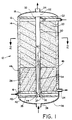
- Figure 1 is a cross sectional representation of the reforming apparatus of the present invention.
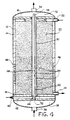
- Figure 2 is a cross sectional representation of the reforming apparatus of Figure 1 taken along lines 2.
- Figure 3 is a cross sectional representation similar to Figure 2 but showing another embodiment of the present invention.
- Figure 4 is a cross sectional representation, similar to Figure 1, of another embodiment of the invention which uses a perforated fuel feed tube.
- Figure 5 is a cross sectional representation of yet another embodiment of the present invention, which uses a bayonet combustion tube.
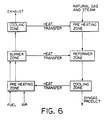
- Figure 6 is a block diagram of a methane reforming process which illustrates the present invention.
- the reaction apparatus 10 is shown generally in Figure 1. Although it is oriented vertically, it should be appreciated that it could be operated horizontally, and so is not limited to a particular orientation.
- the apparatus comprises a steel shell 12 lined inside with a refractory insulation material 14 having a bottom plate 16 (which may also be referred to as a tube sheet) sealed, by gaskets and bolting or the like, to the steel shell, and a top plate 18 (or top tube sheet), which together define the reaction vessel.
- the bottom plate 16 supports a catalyst bed 20 through which passes one or more combustion tubes 30, which are made of a ceramic material and are sealed to bottom plate 16 and top plate 18.
- the shape of the reformer 10 is generally cylindrical and could be described as somewhat similar in construction to a shell and tube heat exchanger.
- the ceramic burner tubes are sealed to plates 16 and 18 by a hollow screw (not shown) threaded into the tube sheet at the end of the tube in combination with a steel pressure ring which expands a graphite seal, preferably a graphite foil spiral wrapped annular cylinder seal (such as Grafoil brand foil from Union Carbide).
- a graphite seal preferably a graphite foil spiral wrapped annular cylinder seal (such as Grafoil brand foil from Union Carbide).
- each tube may be desirable to apply an axial compressive force or preload to each tube, which will tend to neutralize or subtract from the axial tensile stresses produced by heat flows, by incorporating, e.g., in the tube seal assembly a stack of Belleville type springs (not shown) or the like.
- the seals could be held in place by a device which also provides the axial compressive force.
- a feature of the present design is that it allows for the use of lower temperature seals where the combustion tube or tubes are joined to the tube sheet.
- Steel shell 12 has one or more feed inlets 22 for passing the feed gas mixture which is to be reformed into the reformer and down through the packed bed 20 to exit through one or more product outlet(s) 24.
- the feed gas mixture may be a mixture of natural gas and steam if the endothermic reaction is methane reforming reaction, although the mixture could be natural gas and water, which converts to steam in the reactor, or only natural gas, with the steam coming from water fed separately into the reactor.
- the catalytic bed 20 which can be nickel on an alumina, inert support, or other appropriate catalyst, could include an inert section or zone 26, or the entire bed could consist of a single catalyst material or plural catalyst materials. In fact, the apparatus could be operated without a catalyst for some endothermic reactions.
- a fuel feed tube 34 Located concentrically inside combustion tube 30 is a fuel feed tube 34, which can be made from a metal alloy or a ceramic material. Fuel feed tube 34 is fixed to outer plate (or tube sheet) 35 by welding, using an o-ring or graphite foil seal 37. Fuel is fed from inlet 36 into fuel inlet manifold 38 to fuel feed tube 34. Air is fed via air inlet 40 to air inlet manifold 42 which is defined by outer plate 35 which is spaced apart from tube sheet 16 and which communicates with combustion tube 30 via annular inlet 44 so that air will flow in the annular space between the outer wall of fuel tube 34 and the inner wall of combustion tube 30. The combination of combustion tube 30 and fuel feed tube 34, constitute the heat generating means for the reactor.
- the fuel gas is any clean fuel to which sufficient water vapor has been added (if necessary) to prevent coking prior to its combustion. If the fuel contains a high carbon level, it will require some preheating to maintain the necessary humidity level without condensation.
- a resistance heating coil 46 is used inside the outer shell wall 12 of the reactor for cold starting the reactor.
- the resistance heater will preheat the adjacent zone to approximately 600°C (which will be more or less, depending upon the specific fuel being used), at which point auto-ignition of the fuel and air can occur. It may be necessary to flow air through until preheating is complete when the gas can be introduced to produce ignition in flame zone 50.
- the exhaust from combustion tube 30 is collected in exhaust manifold 52 and passes out exhaust outlet 54 which is in communication with manifold 52.
- the ceramic combustion tube 30 is preferably made from sintered alumina and can be made by any of the various available processes for making and shaping dense (impervious) ceramic bodies. Also, there is no criticality in the use of alumina and other ceramic compositions can be used.
- U.S. Patent No. 4,346,049 to J.A. Coppola et al. teaches a silicon carbide composition and process for producing sintered alpha silicon carbide ceramic bodies, the teachings of which are incorporated herein by reference, and such could be used to make the ceramic tube.
- Other ceramic compositions that could be employed include silicon nitride, aluminum nitride, sialon, or the like. The exact material preferred will depend upon the reactants and reaction products involved in the process, as well as temperature and pressure conditions.
- the steel shell 12, bottom plate 16, top plate 18, manifolds 38 and 52, and outer plate 35 are preferably made of conventional pressure-vessel steel which is designed and rated for the reformer internal pressure of up 1200 psi or more and for temperatures of up to about 350°C.
- the refractory insulation 14 is preferably an erosion-resistant, low-conductivity type insulation such as an alumina composition with expansion joints used as required. The refractory should be rated for at least 1300°C continuous duty.
- FIG 2 shows a cross section of reformer 10 along lines 2-2 in Figure 1.
- fuel tube 34 is located concentrically within combustion tube 30 which in turn is surrounded by catalyst bed 20 inside insulated steel shell 12.
- the heat from combustion tube 30 will be transferred into catalyst bed 20 for effecting the endothermic reaction to reform the mixture of steam and light hydrocarbons.
- the use of external pressure surrounding the combustion tube 30 has the very significant advantage of placing the tube in a compressive stress state, where ceramics are much stronger than they are in tension.
- the design could consist of more than one burner tube with Figure 3 illustrating seven burner tubes in an appropriate pattern.
- the invention is not limited to the use of one or seven, and is contemplated that as many as many thousands of combustion tubes could be incorporated in an appropriate size reformer apparatus.
- the use of small-diameter ceramic combustion tubes and graphite foil seals facilitates a denser packing of burner tubes than has been previously available in prior art apparatus.
- the air supplied to inlet 40 could be supplied by a blower or a compressor depending upon the desired pressure drop, heat transfer requirements, and operation employed.
- a compressor will generate a higher inlet pressure than a blower, however, the cost of operating a blower would be less than operating a compressor.
- the apparatus shown in Figures 4 and 5 are basically similar to that shown in Figure 1 in that they include the shell 12, which contains a catalyst bed 20, and has feed inlet 22 and product outlet 24.
- the difference in these embodiments lies in the design of the heat generating means, although in each case, it is enclosed by the reaction vessel.
- combustion tube 30 has a feed gas tube 60 which has perforations or holes 64 at spaced intervals along its length and has one end 66 plugged or otherwise closed.
- fuel fed via inlet 36 into manifold 38 will pass down tube 60 until it exits via the perforations 64.
- the fuel will mix with the air fed via inlet 40 to manifold 42 and into the burner zone 68 and auto-ignite to heat the reactor.
- plug 66 need not resist very hot temperatures and thus could be made of graphite or heat resistant organic cement. Other methods for the staged introduction of the fuel could also be employed.
- the design in Figure 5 differs in that the heat generating means is a bayonet type heat generating means.
- the tube sheet is replaced by an insulated vessel closure 70 and the combustion tube is a closed end tube 80 sealed to plate 18.
- the combustion tube is shown with a closed end but it could be a plugged design as shown in Figure 4.
- the fuel is fed via fuel inlet 82 to fuel feed tube 84, while air is fed via air inlet 86 to air feed tube 88.
- the fuel will auto-ignite in flame zone 90 to produce the heat for conducting the endothermic reaction.
- the exhaust gases will pass up combustion tube 80, as shown by arrow 92 to manifold 52 where they exit the apparatus via exhaust line 54.
- the combustion tubes require a length to inside diameter ratio of typically 500 to 700 in order to achieve the required heat transfer per unit of flow volume for a natural gas plus steam reforming application. Even higher ratios are needed, if the reactor is to operate with low temperature differentials.
- the preferred tube separation distance is quite small; for example 0.3 to 0.5 inches. It is limited by the required sizes of the seals and their associated threads and the need to have some small distance between these threads. Small distances lead to smaller vessel sizes and improved shell-side heat transfer.
- the number of tubes in a single reactor could be as few as one to as many as 10,000 or more. Larger reactors will require thicker pressure-vessel walls, but will save on installation costs.
- the preferred tube wall thickness will depend upon tube strength, corrosion rates, and diameter.
- the use of external pressure will permit the use of relatively thin walls, since ceramics are much stronger in tension than compression.
- the preferred combustion tube inside diameter is usually equal to the tube separation distance (expressed as inside tube to inside tube surface).
- the preferred tube ID would be 0.4 inches for a centerline spacing of 0.8 inches.
- An equilateral triangular tube arrangement is preferred for maximum packing density.
- one design could use 10,000 tubes, each 0.4 inch ID x 0.5 inch OD x 20 feet long on 0.8 inch triangular pitch.
- the bundle diameter would be about 7 feet and the total inside-surface area would be about 20,900 square feet.
- the base-case embodiment employs a fuel and air stream entering the reactor at the same end where the process gas exits and flowing countercurrent to the process gas, with the exhaust leaving at the opposite end, where the process feed enters.
- Another variation would arrange cocurrent flow of combustion gases and process gases. This scheme would require a hot seal on the exhaust end of the ceramic tubes. Such a seal might be made of fused glass or a ceramic cement, for example.
- the cold-end seal could be an O-ring or graphite foil type to allow tube thermal expansion.
- Closed-end, triple-concentric combustion tubes might be used, with the combustion gas exiting at the same end of the reactor where the air and fuel enter. This is illustrated in Figure 5.
- the open ends of these concentric tubes might be at either the process feed or at the process exit end of the reactor.
- the reforming catalyst and its ceramic support particles must be chosen according to a number of criteria.
- the catalyst must maintain sufficient activity over a long period of time at the high bed temperatures. It should be strong enough to support the bed weight above it. It should have a particle size which is small enough to properly fill the spaces between the tubes but large enough to minimize pressure drop through the bed to an acceptable value. It should not sinter-bond excessively to itself or to the tubes upon long exposures at the high temperatures.
- a suitable form of nickel on alumina is one possible candidate, but other catalysts are also reported to be suitable.
- either a high-temperature shift catalyst and/or a low-temperature shift catalyst can optionally be placed within the reactor in the zone where the process gas is cooling and this will cause most of the CO to react with excess H2O to form more H2 with CO2 as a byproduct (the so-called "water-gas shift" reaction).
- syngas is desired for ammonia synthesis
- an appropriate (usually small) proportion of compressed air may be added to the natural gas and steam, such that the product syngas will contain the desired ratio of H2 to N2 (usually 3:1).
- This air addition will react in the catalyst bed during heatup, but will be low enough so as not to produce an excessive local temperature rise in the bed. The overall reaction will remain endothermic.
- This method for making ammonia syngas does not require the addition of any oxygen aside from the air itself, which is a desirable cost savings versus some competing processes which require the separation of oxygen from the air.
- Cold reactor preheat could be achieved alternatively by other means than the electric resistance heater shown.
- hot combustion gases could be introduced through supplementary nozzles in the reactor and circulated through the desired region.
- the upper operating temperature of the graphite foil seals is limited by oxidation by the air present on one side. If a controlled very slow leakage of process gas is permitted to occur through the seal, this could sweep this air away from the seal material and permit the seals to exhibit long life at higher temperatures. Such an arrangement may be termed a purged seal condition.
- thermal insulation might be used inside the pressure vessel.
- the maximum temperature of the combustion gases within the combustion tubes may be varied by adjusting the fuel composition and the fuel and air flow rates. Increasing the air flow rate progressively above the stoichiometric ratio will progressively lower the maximum local temperatures. Steam additions to the fuel can also reduce maximum temperatures.
- the reactor maximum process temperature can vary widely, as required. However, if the auto ignition condition is to be maintained, reactors using maximum process temperatures below about 500°C (depending upon the choice of fuel) will normally require the selection of one of the closed-end combustion tube variants. In these cases, the maximum process temperature could be as low as perhaps 100°C.
- the reactor (shell-side) fluid could be of many different types, including gases, boiling liquids, liquids, or slurries containing fine solids. Gas to liquid condensation might also desirably occur in the coolest zone of the reactor.
- the combustion tubes might be made of various ceramics, depending upon the service conditions (temperature, corrosion, stresses, etc.).
- alumina in addition to alumina, other possible materials for some applications would be carbide ceramics such as silicon carbide or other oxide ceramics such as mullite, stabilized zirconia, or the like.
- carbide ceramics such as silicon carbide or other oxide ceramics such as mullite, stabilized zirconia, or the like.
- the use of external pressure will be a major advantage in controlling the combined stresses in the ceramic tubes to acceptable levels.
- Still other materials are also possible, such as metal tubes for lower-temperature applications.
- a reforming catalyst might also be positioned within the tube 34 to cause the fuel to partially reform during its heatup and hence to both absorb more heat from the process gas (improving cooling) and to simultaneously increase the heating value of the fuel gas (improving heating).
- a feed containing 2.5 volumes steam plus 1.0 volume natural gas (with an assumed composition of 90 volume percent CH4, 7% C2H6, 2% N2, and 1% CO2) is passed through either a conventional reformer or this invention.
- the conventional reformer is similar to that described by Dwyer et al. (U.S. Patent No. 3,132,010) with a hot-zone reaction pressure of 155 psia, whereas the example of this invention uses 1070 psia for this pressure.
- the computed syngas compositions listed in Table 1 are based upon thermodynamic equilibrium compositions at the above pressures and at temperatures 20°C below the stated Table 1 peak temperatures. The compositions are tabulated after condensing water to 40°C.
- the advantages of the apparatus of the present invention are that the syngas pressure is much higher, thus eliminating or reducing the need for syngas compressors, the methane conversion percentage is much higher, the syngas CO/H2 ratio is much higher, and the syngas CO/CO2 ratio is much higher.
- the new process may, if desired, be operated at still higher temperatures to obtain still higher methane conversions. CO/H2 ratios, and CO/CO2 ratios. It may also be operated at either higher or lower pressures and/or steam ratios.
- the ceramic tubes are less prone to coking than are metallic tubes under conditions of low steam ratios.
- the new invention allows very high rates of heat transfer per unit of reactor vessel volume.
- the average rate of heat exchange between the process gas and the air/fuel/exhaust flow was calculated to be some 7 MW/m3 for the reformer internal volume for a reformer design in accordance with the present invention and based upon the stated example, and this figure is more than a factor of ten above the corresponding value for a typical radiant reformer.
Landscapes
- Chemical & Material Sciences (AREA)
- Chemical Kinetics & Catalysis (AREA)
- Organic Chemistry (AREA)
- Health & Medical Sciences (AREA)
- General Health & Medical Sciences (AREA)
- Engineering & Computer Science (AREA)
- Combustion & Propulsion (AREA)
- Inorganic Chemistry (AREA)
- Physics & Mathematics (AREA)
- Fluid Mechanics (AREA)
- Devices And Processes Conducted In The Presence Of Fluids And Solid Particles (AREA)
- Hydrogen, Water And Hydrids (AREA)
- Physical Or Chemical Processes And Apparatus (AREA)
- Transition And Organic Metals Composition Catalysts For Addition Polymerization (AREA)
- Feeding And Controlling Fuel (AREA)
- Yarns And Mechanical Finishing Of Yarns Or Ropes (AREA)
- Finish Polishing, Edge Sharpening, And Grinding By Specific Grinding Devices (AREA)
- Steering Control In Accordance With Driving Conditions (AREA)
- Power Steering Mechanism (AREA)
- Surgical Instruments (AREA)
Claims (28)
- Reaktionsapparat, mit:
einem Reaktionsgefäß zum Bewirken einer endothermischen Reaktion, und
wenigstens einer Wärmeerzeugungseinrichtung zum Erwärmen des Reaktionsgefäßes, wobei die Wärmeerzeugungseinrichtung von dem Reaktionsgefäß umschlossen ist;
wobei das Reaktionsgefäß aufweist: eine Eingabeeinrichtung zum Zuführen eines Zufuhrgases, welches der endothermischen Reaktion zu unterziehen ist, was dazu führt, daß in dem Reaktionsgefäß ein Produktgas erzeugt wird, und eine Ausgabeeinrichtung zum Entfernen des Produktgases aus dem Reaktionsgefäß; und
wobei die Wärmeerzeugungseinrichtung wenigstens ein keramisches oder metallisches Verbrennungsrohr aufweist, das ein Brennstoffzufuhrrohr konzentrisch umgibt, welches sich wenigstens teilweise über die Länge und im Inneren des Verbrennungsrohres erstreckt, wobei die Wärmeerzeugungseinrichtung aufweist: eine Einrichtung zur Zufuhr von Brennstoff zu dem Brennstoffzufuhrrohr und von Luft zu dem Verbrennungsrohr, wodurch der Brennstoff in dem Verbrennungsrohr verbrennt und Wärme erzeugt, die von dem Verbrennungsrohr in das Reaktionsgefäß übertragen wird, und eine Einrichtung zum Entfernen von Abgasen aus der Wärmeerzeugungseinrichtung,
wobei der Apparat gekennzeichnet ist durch die separate Zufuhr von Luft und Brennstoff durch eine Vorwärmzone innerhalb des Reaktionsgefäßes, wobei von wenigstens einem von Produktgas und Abgasen Wärme auf die Luft und den Brennstoff übertragen wird, um die Luft und den Brennstoff vor der Verbrennung vorzuwärmen. - Apparat nach Anspruch 1, dadurch gekennzeichnet, daß der Einlaß des Brennstoffes in das Reaktionsgefäß sich an dem Ende befindet, das dem Einlaß des Zufuhrgases in das Gefäß gegenüberliegt.
- Apparat nach Anspruch 2, dadurch gekennzeichnet, daß sich der Einlaß des Zufuhrgases in das Reaktionsgefäß an dessen erstem Ende befindet und der des Kraftstoffs in die Wärmeerzeugungseinrichtung am dem ersten Ende gegenüberliegenden Ende, wodurch die Ströme der Reaktion und der Verbrennung gegenläufig sind.
- Apparat nach einem der vorhergehenden Ansprüche, dadurch gekennzeichnet, daß der Einlaß der Luft- und Brennstoffströme in das Reaktionsgefäß sich am selben Ende wie der Auslaß des Produktgases befindet und die Ströme gegenläufig zu dem Produktgas strömen, wobei die Abgase an dem Ende austreten, das dem Ende des Eintritts des Zufuhrgases gegenüberliegt.
- Apparat nach einem der vorhergehenden Ansprüche, dadurch gekennzeichnet, daß er mehrere Verbrennungsrohre aufweist.
- Apparat nach einem der vorhergehenden Ansprüche, dadurch gekennzeichnet, daß er wenigstens ein Verbrennungsrohr aufweist, welches durch Dichtungen, die eine Wärmeausdehnung des Verbrennungsrohres zulassen, in Kontakt mit dem Reaktionsgefäß befestigt ist.
- Apparat nach Anspruch 6, dadurch gekennzeichnet, daß er Dichtungen aufweist, die Graphitdichtungen sind.
- Apparat nach einem der Ansprüche 5-7, dadurch gekennzeichnet, daß er mehrere Rohre aufweist, die sich jeweils unabhängig voneinander thermisch ausdehnen können.
- Apparat nach einem der vorhergehenden Ansprüche, dadurch gekennzeichnet, daß er wenigstens ein Verbrennungsrohr mit einer einzigen Wand zwischen der endothermischen Reaktion und der Verbrennung aufweist.
- Apparat nach einem der vorhergehenden Ansprüche, dadurch gekennzeichnet, daß er wenigstens eine inerte Zone in dem Reaktionsgefäß aufweist.
- Apparat nach Anspruch 10, gekennzeichnet durch eine die Vorwärmzone umgebende inerte Zone.
- Apparat nach einem der vorhergehenden Ansprüche, dadurch gekennzeichnet, daß das Reaktionsgefäß ein Katalysatorbett aufweist, welches das Reaktionsgefäß wenigstens teilweise füllt, um die endothermische Reaktion zu erleichtern.
- Apparat nach Anspruch 10, dadurch gekennzeichnet, daß das Katalysatorbett wenigstens zwei Katalysatorzonen aufweist.
- Apparat nach Anspruch 13, dadurch gekennzeichnet, daß er ein Katalysatorbett mit einem ersten Abschnitt mit einem ersten Katalysator für eine erste Reaktion und einem zweiten Abschnitt mit einem zweiten Katalysator für eine zweite Reaktion aufweist.
- Apparat nach einem der vorhergehenden Ansprüche, dadurch gekennzeichnet, daß er wenigstens ein keramisches Verbrennungsrohr aufweist.
- Apparat nach Anspruch 15, dadurch gekennzeichnet, daß das keramische Verbrennungsrohr aus der Gruppe gewählt ist, die aus Aluminiumoxid, Siliziumkarbid, Aluminiumnitrid, Siliziumnitrid oder Sialon besteht.
- Apparat nach Anspruch 16, dadurch gekennzeichnet, daß er ein Aluminiumoxidverbrennungsrohr aufweist.
- Appparat nach einem der Ansprüche 1-14, dadurch gekennzeichnet, daß er ein Metallverbrennungsrohr aufweist.
- Appparat nach einem der vorhergehenden Ansprüche, dadurch gekennzeichnet, daß das Reaktionsgefäß ein wenigstens ein Verbrennungsrohr umgebendes, im wesentlichen zylindrisches Gehäuse aufweist.
- Apparat nach Anspruch 19, dadurch gekennzeichnet, daß das Gehäuse aus Metall besteht.
- Apparat nach Anspruch 19 oder 20, dadurch gekennzeichnet, daß das Gehäuse ferner eine Isolierschicht auf seiner Innenfläche aufweist.
- Apparat nach einem der vorhergehenden Ansprüche, dadurch gekennzeichnet, daß er eine Einrichtung zum Vorwärmen der Luft aufweist.
- Apparat nach einem der vorhergehenden Ansprüche, dadurch gekennzeichnet, daß zwischen dem Verbrennungsrohr und dem Brennstoffzufuhrrohr ein Ringraum vorhanden ist und die Luft über den Ringraum in das Verbrennungsrohr eintritt.
- Apparat nach einem der vorhergehenden Ansprüche, dadurch gekennzeichnet, daß das Brennstoffzufuhrrohr ein Metallrohr aufweist.
- Apparat nach einem der Ansprüche 1-23, dadurch gekennzeichnet, daß das Brennstoffzufuhrrohr ein Keramikrohr aufweist.
- Apparat nach einem der vorhergehenden Ansprüche, dadurch gekennzeichnet, daß das Verbrennungsrohr durch eine Einrichtung befestigt wird, die eine Axialdruckkraft auf das Rohr aufbringt.
- Verfahren zum Bewirken einer endothermischen Reaktion, dadurch gekennzeichnet, daß es den Schritt der Verwendung eines Reaktionsapparates nach einem der vorhergehenden Ansprüche aufweist.
- Verfahren nach Anspruch 27, dadurch gekennzeichnet, daß Luft und Brennstoff separat in der Vorwärmzone erwärmt werden, so daß sie bei Vermischung in dem Verbrennungsrohr selbstzünden.
Applications Claiming Priority (2)
| Application Number | Priority Date | Filing Date | Title |
|---|---|---|---|
| US50437590A | 1990-04-03 | 1990-04-03 | |
| US504375 | 1990-04-03 |
Publications (2)
| Publication Number | Publication Date |
|---|---|
| EP0450872A1 EP0450872A1 (de) | 1991-10-09 |
| EP0450872B1 true EP0450872B1 (de) | 1994-11-23 |
Family
ID=24006004
Family Applications (1)
| Application Number | Title | Priority Date | Filing Date |
|---|---|---|---|
| EP91302767A Expired - Lifetime EP0450872B1 (de) | 1990-04-03 | 1991-03-28 | Endothermischer Reaktionsapparat |
Country Status (10)
| Country | Link |
|---|---|
| EP (1) | EP0450872B1 (de) |
| JP (1) | JP3075757B2 (de) |
| KR (1) | KR0170398B1 (de) |
| AT (1) | ATE114253T1 (de) |
| AU (2) | AU7356491A (de) |
| BR (1) | BR9101266A (de) |
| CA (1) | CA2038289C (de) |
| DE (1) | DE69105230T2 (de) |
| DK (1) | DK0450872T3 (de) |
| ZA (1) | ZA911838B (de) |
Cited By (3)
| Publication number | Priority date | Publication date | Assignee | Title |
|---|---|---|---|---|
| US6162267A (en) * | 1998-12-11 | 2000-12-19 | Uop Llc | Process for the generation of pure hydrogen for use with fuel cells |
| DE19855769B4 (de) * | 1998-12-03 | 2008-10-09 | Nucellsys Gmbh | Katalytisch beheizte Komponente für einen chemischen Reaktor |
| WO2026012935A1 (en) * | 2024-07-08 | 2026-01-15 | Topsoe A/S | Multiple-bed catalytic reactor comprising sandwich tube sheet |
Families Citing this family (34)
| Publication number | Priority date | Publication date | Assignee | Title |
|---|---|---|---|---|
| US6153152A (en) * | 1990-04-03 | 2000-11-28 | The Standard Oil Company | Endothermic reaction apparatus and method |
| US5567398A (en) * | 1990-04-03 | 1996-10-22 | The Standard Oil Company | Endothermic reaction apparatus and method |
| US6096106A (en) * | 1990-04-03 | 2000-08-01 | The Standard Oil Company | Endothermic reaction apparatus |
| AU661877B2 (en) * | 1990-04-03 | 1995-08-10 | Standard Oil Company, The | Endothermic reaction apparatus |
| DE69631886T2 (de) * | 1996-11-12 | 2004-12-30 | Ammonia Casale S.A. | Reformierungsanlage |
| AU775023B2 (en) * | 1996-11-12 | 2004-07-15 | Ammonia Casale S.A. | Use of a seal of the compression ring type |
| US6409974B1 (en) | 1998-12-11 | 2002-06-25 | Uop Llc | Water gas shift process and apparatus for purifying hydrogen for use with fuel cells |
| US7025940B2 (en) * | 1997-10-08 | 2006-04-11 | Shell Oil Company | Flameless combustor process heater |
| DE19813053C2 (de) | 1998-03-25 | 2001-10-18 | Xcellsis Gmbh | Reaktoreinheit für eine katalytische chemische Reaktion, insbesondere zur katalytischen Methanolreformierung |
| US6616909B1 (en) * | 1998-07-27 | 2003-09-09 | Battelle Memorial Institute | Method and apparatus for obtaining enhanced production rate of thermal chemical reactions |
| EP1136444B1 (de) * | 2000-03-22 | 2012-05-09 | Ammonia Casale S.A. | Verfahren zur Kohlenwasserstoffreformierung |
| FR2807746B1 (fr) * | 2000-04-13 | 2002-12-13 | Air Liquide | Procede de production d'un melange comportant de l'hydrogene et du co |
| EP1249272A1 (de) * | 2001-04-11 | 2002-10-16 | Ammonia Casale S.A. | Dichtungsvorrichtung für chemische Reaktoren |
| JP2002326805A (ja) * | 2001-04-27 | 2002-11-12 | Daikin Ind Ltd | 改質装置及びこれを備える燃料電池システム |
| JP4762496B2 (ja) * | 2004-01-06 | 2011-08-31 | 東京瓦斯株式会社 | 触媒反応装置 |
| US20080066438A1 (en) * | 2004-06-02 | 2008-03-20 | Ebara Ballard Corporation | Fuel Treating Device |
| DE102004059014B4 (de) | 2004-12-08 | 2009-02-05 | Lurgi Gmbh | Reaktionsbehälter zur Herstellung von H2 und CO enthaltendem Synthesegas |
| RU2400669C2 (ru) | 2005-03-10 | 2010-09-27 | Шелл Интернэшнл Рисерч Маатсхаппий Б.В. | Способ пуска системы непосредственного нагревания (варианты), способ пуска устройства непосредственного нагревания (варианты) |
| EP1856443B1 (de) * | 2005-03-10 | 2015-08-12 | Shell Internationale Research Maatschappij B.V. | Mehrfachröhren-wärmeübertragungssystem zur verbrennung eines brennstoffs und zur erhitzung einer prozessflüssigkeit sowie verwendung davon |
| CA2601359A1 (en) * | 2005-03-10 | 2006-09-21 | Shell Internationale Research Maatschappij B.V. | A heat transfer system for the combustion of a fuel and heating of a process fluid and a process that uses same |
| FR2914395B1 (fr) * | 2007-03-30 | 2009-11-20 | Inst Francais Du Petrole | Nouveau reacteur echangeur compact utilisant un bruleur poreux |
| US20100055518A1 (en) * | 2008-08-26 | 2010-03-04 | Idatech, Llc | Hydrogen-producing assemblies, fuel cell systems including the same, methods of producing hydrogen gas, and methods of powering an energy-consuming device |
| US8441361B2 (en) | 2010-02-13 | 2013-05-14 | Mcallister Technologies, Llc | Methods and apparatuses for detection of properties of fluid conveyance systems |
| AU2011216244A1 (en) * | 2010-02-13 | 2012-09-06 | Mcalister Technologies, Llc | Reactor vessels with transmissive surfaces for producing hydrogen-based fuels and structural elements, and associated systems and methods |
| BR112012020280A2 (pt) * | 2010-02-13 | 2016-05-03 | Mcalister Technologies Llc | sistema reator químico e método para operar uma máquina e um reator químico |
| CN102829181A (zh) * | 2011-06-16 | 2012-12-19 | 阿梅尼亚·卡萨莱股份有限公司 | 用于化学反应器的密封装置 |
| WO2013025650A1 (en) | 2011-08-12 | 2013-02-21 | Mcalister Technologies, Llc | Mobile transport platforms for producing hydrogen and structural materials and associated systems and methods |
| ITVR20120101A1 (it) * | 2012-05-18 | 2013-11-19 | I C I Caldaie S P A | Struttura di reattore chimico |
| AU2014346844B2 (en) | 2013-11-06 | 2017-06-15 | Watt Fuel Cell Corp. | Chemical reactor with manifold for management of a flow of gaseous reaction medium thereto |
| WO2018046590A1 (en) | 2016-09-09 | 2018-03-15 | Shell Internationale Research Maatschappij B.V. | Process for the preparation of hydrogen |
| MY189567A (en) * | 2017-04-25 | 2022-02-17 | Bin Halim Rasip Amin | Reaction chamber for exothermic and endothermic reactions |
| CN110947354A (zh) * | 2019-12-31 | 2020-04-03 | 淮阴工学院 | 一种甲烷氢氯化反应器 |
| US12403445B2 (en) | 2020-07-23 | 2025-09-02 | Topsoe A/S | Structured catalyst |
| US20240269662A1 (en) * | 2021-06-28 | 2024-08-15 | Topsoe A/S | A structured catalyst |
Family Cites Families (3)
| Publication number | Priority date | Publication date | Assignee | Title |
|---|---|---|---|---|
| GB1039756A (en) * | 1962-10-29 | 1966-08-24 | Gas Council | Improvements in or relating to methods of treating gases |
| US4157241A (en) * | 1976-03-29 | 1979-06-05 | Avion Manufacturing Co. | Furnace heating assembly and method of making the same |
| JPS55154303A (en) * | 1979-05-18 | 1980-12-01 | Toyo Eng Corp | Method and apparatus for steam-reforming hydrocarbon |
-
1991
- 1991-03-13 ZA ZA911838A patent/ZA911838B/xx unknown
- 1991-03-14 AU AU73564/91A patent/AU7356491A/en not_active Abandoned
- 1991-03-14 CA CA002038289A patent/CA2038289C/en not_active Expired - Fee Related
- 1991-03-28 DE DE69105230T patent/DE69105230T2/de not_active Expired - Fee Related
- 1991-03-28 BR BR9101266-0A patent/BR9101266A/pt not_active IP Right Cessation
- 1991-03-28 EP EP91302767A patent/EP0450872B1/de not_active Expired - Lifetime
- 1991-03-28 DK DK91302767.8T patent/DK0450872T3/da active
- 1991-03-28 AT AT91302767T patent/ATE114253T1/de not_active IP Right Cessation
- 1991-04-02 JP JP03070019A patent/JP3075757B2/ja not_active Expired - Fee Related
- 1991-04-02 KR KR1019910005313A patent/KR0170398B1/ko not_active Expired - Fee Related
-
1995
- 1995-11-09 AU AU37774/95A patent/AU698930B2/en not_active Ceased
Cited By (3)
| Publication number | Priority date | Publication date | Assignee | Title |
|---|---|---|---|---|
| DE19855769B4 (de) * | 1998-12-03 | 2008-10-09 | Nucellsys Gmbh | Katalytisch beheizte Komponente für einen chemischen Reaktor |
| US6162267A (en) * | 1998-12-11 | 2000-12-19 | Uop Llc | Process for the generation of pure hydrogen for use with fuel cells |
| WO2026012935A1 (en) * | 2024-07-08 | 2026-01-15 | Topsoe A/S | Multiple-bed catalytic reactor comprising sandwich tube sheet |
Also Published As
| Publication number | Publication date |
|---|---|
| JP3075757B2 (ja) | 2000-08-14 |
| AU3777495A (en) | 1996-01-18 |
| JPH0596149A (ja) | 1993-04-20 |
| EP0450872A1 (de) | 1991-10-09 |
| AU698930B2 (en) | 1998-11-12 |
| AU7356491A (en) | 1991-12-19 |
| DE69105230D1 (de) | 1995-01-05 |
| BR9101266A (pt) | 1991-11-26 |
| ZA911838B (en) | 1991-12-24 |
| KR0170398B1 (ko) | 1999-01-15 |
| KR910018071A (ko) | 1991-11-30 |
| DK0450872T3 (da) | 1994-12-12 |
| CA2038289A1 (en) | 1991-10-04 |
| CA2038289C (en) | 2002-02-19 |
| ATE114253T1 (de) | 1994-12-15 |
| DE69105230T2 (de) | 1995-05-18 |
Similar Documents
| Publication | Publication Date | Title |
|---|---|---|
| EP0450872B1 (de) | Endothermischer Reaktionsapparat | |
| AU661877B2 (en) | Endothermic reaction apparatus | |
| US6096106A (en) | Endothermic reaction apparatus | |
| EP0703823B1 (de) | Endothermischer reaktionsapparat | |
| US5229102A (en) | Catalytic ceramic membrane steam-hydrocarbon reformer | |
| CN101432065B (zh) | 固定床吸热反应内燃交换反应器 | |
| US4909809A (en) | Apparatus for the production of gas | |
| US5156821A (en) | Reactor for reforming hydrocarbon | |
| US6153152A (en) | Endothermic reaction apparatus and method | |
| JP3834069B2 (ja) | 吸熱反応装置 | |
| JP4850696B2 (ja) | 圧力スイング改質を使用する水素製造 | |
| EP1063008A2 (de) | Reaktor zur Durchführung eines nicht-adiabatischen Verfahren | |
| KR100241568B1 (ko) | 흡열 반응장치 및 이 반응을 수행하기 위한 방법 | |
| JPS61232203A (ja) | 水素含有ガスを生成する方法 | |
| NZ245475A (en) | Endothermic reaction vessel with metallic reaction tube in thermal contact with combustion zone | |
| SA93140127B1 (ar) | عملية تفاعل ماص للحرارة | |
| JPS62201632A (ja) | 改質装置 |
Legal Events
| Date | Code | Title | Description |
|---|---|---|---|
| PUAI | Public reference made under article 153(3) epc to a published international application that has entered the european phase |
Free format text: ORIGINAL CODE: 0009012 |
|
| AK | Designated contracting states |
Kind code of ref document: A1 Designated state(s): AT BE CH DE DK ES FR GB GR IT LI LU NL SE |
|
| 17P | Request for examination filed |
Effective date: 19920316 |
|
| 17Q | First examination report despatched |
Effective date: 19921127 |
|
| GRAA | (expected) grant |
Free format text: ORIGINAL CODE: 0009210 |
|
| AK | Designated contracting states |
Kind code of ref document: B1 Designated state(s): AT BE CH DE DK ES FR GB GR IT LI LU NL SE |
|
| PG25 | Lapsed in a contracting state [announced via postgrant information from national office to epo] |
Ref country code: CH Effective date: 19941123 Ref country code: NL Effective date: 19941123 Ref country code: GR Free format text: LAPSE BECAUSE OF FAILURE TO SUBMIT A TRANSLATION OF THE DESCRIPTION OR TO PAY THE FEE WITHIN THE PRESCRIBED TIME-LIMIT Effective date: 19941123 Ref country code: ES Free format text: THE PATENT HAS BEEN ANNULLED BY A DECISION OF A NATIONAL AUTHORITY Effective date: 19941123 Ref country code: BE Effective date: 19941123 Ref country code: AT Effective date: 19941123 Ref country code: LI Effective date: 19941123 |
|
| REF | Corresponds to: |
Ref document number: 114253 Country of ref document: AT Date of ref document: 19941215 Kind code of ref document: T |
|
| REG | Reference to a national code |
Ref country code: DK Ref legal event code: T3 |
|
| ITF | It: translation for a ep patent filed | ||
| REF | Corresponds to: |
Ref document number: 69105230 Country of ref document: DE Date of ref document: 19950105 |
|
| ET | Fr: translation filed | ||
| PG25 | Lapsed in a contracting state [announced via postgrant information from national office to epo] |
Ref country code: SE Effective date: 19950223 |
|
| REG | Reference to a national code |
Ref country code: CH Ref legal event code: PL |
|
| PG25 | Lapsed in a contracting state [announced via postgrant information from national office to epo] |
Ref country code: LU Free format text: LAPSE BECAUSE OF NON-PAYMENT OF DUE FEES Effective date: 19950331 |
|
| NLV1 | Nl: lapsed or annulled due to failure to fulfill the requirements of art. 29p and 29m of the patents act | ||
| PLBE | No opposition filed within time limit |
Free format text: ORIGINAL CODE: 0009261 |
|
| STAA | Information on the status of an ep patent application or granted ep patent |
Free format text: STATUS: NO OPPOSITION FILED WITHIN TIME LIMIT |
|
| 26N | No opposition filed | ||
| REG | Reference to a national code |
Ref country code: GB Ref legal event code: IF02 |
|
| PGFP | Annual fee paid to national office [announced via postgrant information from national office to epo] |
Ref country code: DK Payment date: 20040123 Year of fee payment: 14 |
|
| PGFP | Annual fee paid to national office [announced via postgrant information from national office to epo] |
Ref country code: DE Payment date: 20040212 Year of fee payment: 14 |
|
| PGFP | Annual fee paid to national office [announced via postgrant information from national office to epo] |
Ref country code: FR Payment date: 20040216 Year of fee payment: 14 |
|
| PG25 | Lapsed in a contracting state [announced via postgrant information from national office to epo] |
Ref country code: IT Free format text: LAPSE BECAUSE OF NON-PAYMENT OF DUE FEES;WARNING: LAPSES OF ITALIAN PATENTS WITH EFFECTIVE DATE BEFORE 2007 MAY HAVE OCCURRED AT ANY TIME BEFORE 2007. THE CORRECT EFFECTIVE DATE MAY BE DIFFERENT FROM THE ONE RECORDED. Effective date: 20050328 |
|
| PG25 | Lapsed in a contracting state [announced via postgrant information from national office to epo] |
Ref country code: DK Free format text: LAPSE BECAUSE OF NON-PAYMENT OF DUE FEES Effective date: 20050331 |
|
| PG25 | Lapsed in a contracting state [announced via postgrant information from national office to epo] |
Ref country code: DE Free format text: LAPSE BECAUSE OF NON-PAYMENT OF DUE FEES Effective date: 20051001 |
|
| PG25 | Lapsed in a contracting state [announced via postgrant information from national office to epo] |
Ref country code: FR Free format text: LAPSE BECAUSE OF NON-PAYMENT OF DUE FEES Effective date: 20051130 |
|
| REG | Reference to a national code |
Ref country code: DK Ref legal event code: EBP |
|
| REG | Reference to a national code |
Ref country code: FR Ref legal event code: ST Effective date: 20051130 |
|
| PGFP | Annual fee paid to national office [announced via postgrant information from national office to epo] |
Ref country code: GB Payment date: 20100326 Year of fee payment: 20 |
|
| REG | Reference to a national code |
Ref country code: GB Ref legal event code: PE20 Expiry date: 20110327 |
|
| PG25 | Lapsed in a contracting state [announced via postgrant information from national office to epo] |
Ref country code: GB Free format text: LAPSE BECAUSE OF EXPIRATION OF PROTECTION Effective date: 20110327 |