EP0450578A2 - Method and apparatus for controlling ultrasonic fragmentation of body tissue - Google Patents
Method and apparatus for controlling ultrasonic fragmentation of body tissue Download PDFInfo
- Publication number
- EP0450578A2 EP0450578A2 EP91105207A EP91105207A EP0450578A2 EP 0450578 A2 EP0450578 A2 EP 0450578A2 EP 91105207 A EP91105207 A EP 91105207A EP 91105207 A EP91105207 A EP 91105207A EP 0450578 A2 EP0450578 A2 EP 0450578A2
- Authority
- EP
- European Patent Office
- Prior art keywords
- tip
- displacement
- vibrational energy
- operative tip
- handpiece assembly
- Prior art date
- Legal status (The legal status is an assumption and is not a legal conclusion. Google has not performed a legal analysis and makes no representation as to the accuracy of the status listed.)
- Granted
Links
Images


Classifications
-
- A—HUMAN NECESSITIES
- A61—MEDICAL OR VETERINARY SCIENCE; HYGIENE
- A61F—FILTERS IMPLANTABLE INTO BLOOD VESSELS; PROSTHESES; DEVICES PROVIDING PATENCY TO, OR PREVENTING COLLAPSING OF, TUBULAR STRUCTURES OF THE BODY, e.g. STENTS; ORTHOPAEDIC, NURSING OR CONTRACEPTIVE DEVICES; FOMENTATION; TREATMENT OR PROTECTION OF EYES OR EARS; BANDAGES, DRESSINGS OR ABSORBENT PADS; FIRST-AID KITS
- A61F9/00—Methods or devices for treatment of the eyes; Devices for putting-in contact lenses; Devices to correct squinting; Apparatus to guide the blind; Protective devices for the eyes, carried on the body or in the hand
- A61F9/007—Methods or devices for eye surgery
- A61F9/00736—Instruments for removal of intra-ocular material or intra-ocular injection, e.g. cataract instruments
- A61F9/00745—Instruments for removal of intra-ocular material or intra-ocular injection, e.g. cataract instruments using mechanical vibrations, e.g. ultrasonic
-
- A—HUMAN NECESSITIES
- A61—MEDICAL OR VETERINARY SCIENCE; HYGIENE
- A61B—DIAGNOSIS; SURGERY; IDENTIFICATION
- A61B17/00—Surgical instruments, devices or methods, e.g. tourniquets
- A61B17/32—Surgical cutting instruments
- A61B17/320068—Surgical cutting instruments using mechanical vibrations, e.g. ultrasonic
- A61B2017/320084—Irrigation sleeves
Definitions
- This invention relates generally to an improved ultrasonic surgical apparatus for enhancing tissue fragmentation.
- an apparatus of this type includes an ultrasonic transducer housed in a handpiece. Such ultrasonic transducers are operable for converting electrical energy supplied thereto into high velocity vibrational movements. The transducer generated ultrasonic vibrations are transmitted to a surgical operative tip that is coupled thereto.
- the operative tip is insertable through a small incision formed in the eye and is manipulated so as to actually contact the cataractous lens.
- Ultrasonic vibrations cause the lens to fragment.
- the tissue fragments and other body fluids including irrigation fluid are aspirated from the surgical site by an aspiration system that includes an aspiration passage extending through the operative tip.
- the aspiration is established by an external vacuum pump located on an external control device.
- the fragmentation of the lens is the result of cutting action introduced by the vibrating tip and the disruptive cavitation developed by the intense ultrasonic field adjacent the operative tip.
- Known prior art ultrasonic devices such as described in U.S. Patent No. 4,750,902, tend to produce high cutting displacement at the operative tip.
- cavitation has a tendency to obscure or cloud the visibility around the operative site so as to hinder the physician during the operation.
- cavitation can be produced by tool portions such as the tip nut or other sections of the ultrasonic horn and can lead to an unnecessary waste of power.
- Ultrasonic surgical devices of the kind discussed above are usually operated at relatively high mechanical displacement. High mechanical displacement generates heat any time a frictional force has to be overcome. Most of the frictional losses are generated within the threads used to couple different sections of the handpiece. It is common practice to use threads for coupling the tip with the horn and to use a threaded bolt for compressing the piezoelectric elements between two metal cylinders in a sandwich-type configuration. If those threads are placed in a high vibrational displacement area then we should expect temperature increases especially if the fluid flow stops due to an occlusion. Besides several ultrasonic surgical aspirators utilize low frequency (i.e., below 40 KHz) which only enhances cavitation and thus eye turbulence.
- low frequency i.e., below 40 KHz
- an ultrasonic apparatus comprising a handpiece assembly.
- the apparatus includes transducer means mounted in the handpiece assembly and being operable for converting electrical power to ultrasonic mechanical vibrational energy.
- motion amplifying means are provided and is acoustically coupled at one end thereof to the transducer means.
- the amplifying means includes an operative tip portion at another end thereof for contacting body tissue to be removed.
- the amplifying means includes a symmetrical step horn portion and an asymmetrical step horn portion being connected in series with each other.
- the operative tip portion is connected to one of the horn portions and is operable for providing a desired degree of displacement at a distal end segment thereof.
- the operative tip portion is part of the symmetrical horn portion and provides substantially zero displacement at its proximal end segment and maximum displacement at a distal end segment thereof.
- a body or asymmetrical portion is connected to the symmetrical horn portion does not substantially amplify displacement of the vibrational energy.
- the transducer means is operable at an anti-resonant frequency of the amplifying means so as to act as a high impedance to the vibrational energy. Accordingly, the vibrational energy will flow substantially to the tip portion and provide a localized region of cavitation about the tip portion under varying loads experienced thereby.
- the asymmetrical step horn portion includes the operative tip, wherein the asymmetrical and symmetrical portions provide a high gain feature for mechanical displacement.
- an aspiration passage means extending through the tip portion and at least partially through the body portion for allowing aspiration of body tissue into a tip opening in response to a source of vacuum being applied to one end of the passage means.
- passage means having an opening at the distal end of the operative tip portion wherein cavitation produced by the operative tip is localized in a region in the form of generally circular fluidic currents.
- the localized region is a few millimeters from the tip opening.
- an ultrasonic apparatus the provisions for an improved method and apparatus for enhancing fragmenting efficiency; the provision for an ultrasonic handpiece which has an ultrasonic horn assembly which yields high displacement magnification; the provision for an ultrasonic handpiece which minimizes frictional losses and power consumption; the provision for an ultrasonic handpiece which includes series connected asymmetrical and symmetrical horn portions, wherein one of the horn portions includes a working operative tip; the provision for an ultrasonic handpiece which provides minimal and highly localized cavitation to a working tip thereof; the provision for an ultrasonic handpiece for use in fragmentation and extraction of cataracts; the provision for an ultrasonic handpiece of the above-noted type which provides high displacement but with significantly reduced power; and the provision for an ultrasonic actuator which utilizes high frequency.
- Fig. 1 for showing an illustrated embodiment of an improved ultrasonically vibrated surgical aspirator apparatus 10 made according to the present invention.
- the aspiration apparatus 10 is, preferably, adapted for use in precisely removing unwanted body tissue, such as cataractous lens tissue.
- Ultrasonic surgical apparatus representative of the type to which this embodiment is directed are known and described in U.S. Patent No. 3,693,613.
- the apparatus 10 can be a modified 500 series handpiece and irrigationiaspiration system manufactured by Alcon Surgical of Irvine, California.
- the ultrasonic surgical apparatus 10 is intended for operation with a control system depicted generally by reference numeral 12.
- the control system 12 allows control of electrical power through leads L to the ultrasonic surgical apparatus 10.
- the control system 12 also includes external fluid conduit 14 that is controlled through the system 12 to supply irrigation fluid from a source (not shown) to the ultrasonic aspirator apparatus 10.
- the control system 12 also includes an aspiration conduit 16 connected to the surgical apparatus 10 for allowing withdrawal of the fragmented tissue particles as well as treatment and body fluids from the operative site.
- Exemplary of the type of control system contemplated for use with the ultrasonic aspirator apparatus 10 is the 10,000 Series control system manufactured by Alcon Surgical of Irvine, California or that described generally in U.S. Patent No. 4,713,051. This latter patent is incorporated herein by reference to provide for a more detailed description of the type control system contemplated.
- the ultrasonic aspirator apparatus 10 includes a handpiece or housing assembly 18 having an outer casing constructed to be held by a surgeon's hand and to isolate the latter from vibrations during use.
- the handpiece assembly 18 supports and houses an ultrasonic transducer assembly 20.
- the transducer assembly 20 includes a pair of opposed piezoelectric crystals 22, such as the PZT, which are sandwiched together between a pair of spaced apart and opposing insulated cylindrical transducer end members 24.
- the transducer assembly 20 is operable, in response to high frequency electrical energy supplied thereto from the control system 12, under the control of a footswitch or the like.
- the transducer assembly 20 When operated, the transducer assembly 20 produces corresponding high frequency mechanical vibrations which are transmitted in a standing wave-pattern.
- the transducer assembly 20 is operable to produce ultrasonic vibrations in a range of, for example, 20 kHz to 100 kHz, and, preferably, in a range of about 60 kHz to 80 kHz.
- an elongated vibration coupling or transmitting rod 26 Directly and centrally coupled to the transducer assembly 20 is an elongated vibration coupling or transmitting rod 26.
- the vibration transmitting rod 26 is also coupled to a surgical or operative tip 28 which together define a vibration transmitting or displacement amplifying device 30.
- the elongated vibration transmitting rod 26 has threaded portions 32 which are threadedly joined to internal threaded portions of the transducer end members 24 as shown in Fig. 1.
- the vibration transmitting rod 26 is also formed with an aspiration conduit or passage 34 extending along the axial extent thereof.
- the aspiration passage 34 fluidically interconnects at one end with a central bore 36 of the operative tip 28 and at the other end to the aspiration conduit 16 leading from the handpiece to a suction pump (not shown) associated with the control system 12. Operation of the suction pump causes fragmented body tissue and fluids present at the surgical site to be aspirated through the operative tip 28 and the handpiece assembly 18 to a suitable collection vessel (not shown) associated with the control system 12.
- the ultrasonic transducer assembly 20 of this embodiment generates longitudinal ultrasonic vibrations which are propagated along the vibration transmitting or wave amplification device 30.
- the propagated vibrational waves have nodal and antinodal points along the standing wave pattern, as seen in Fig. 2C.
- a vibrational nodal point or node is where there is no vibrational movement. Vibrational displacement and velocity increase from about zero (0) at the nodal points to a maximum at antinodal points.
- the antinodal points are located midway between adjacent nodal points. It will be appreciated that the nodal points are separated by a vibrational half-wavelength.
- an antinodal point 35 (Fig.
- FIG. 2C Another vibrational nodal point 35b (Fig. 2C) is located adjacent the threaded junctions between the vibrational transmitting rod 26 and a transducer end member 24. This latter area of no displacement reduces frictional loses between the threaded portions. Also it serves as a region that the housing assembly 18 is connected thereto as by solder or welding. In this latter regard, the housing assembly 18 will have significantly reduced vibrational energy transmitted thereto.
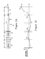
- Fig. 2B schematically illustrates the handpiece of Fig. 2A, but shows the arrangement of half-wavelength step horns associated therewith.
- Reference character A of Fig. 2B depicts a symmetrical step horn portion and reference character B shows an asymmetrical step horn portion.
- the symmetrical portion A includes the operative tip 32 which is a quarter-wavelength resonator.
- the half-wavelength step portions or resonators of Fig. 2B and the actual vibrational wavelength depicted in Fig. 2C differ in length. In other words, the standing wavelength dimensions of Fig. 2C do not coincide with the actual physical lengths of the half-wavelength resonators or step horns A and B.
- a half-wavelength resonator can be defined as a single or composite bar which when driven at a certain frequency, called resonant frequency, experiences the following two conditions: the force at both ends is equal to zero and only one node is generated along the bar.
- Fig. 2D wherein points of force F1-F3 are depicted. These points are of zero force amplitude and coincide with the respective ends of the symmetrical and asymmetrical horn portions A and B.
- the symmetrical portion B is made of two quarter-wavelength sections or resonators one of them being the operative tip 28. As seen in Fig.
- the operative tip 28 has a narrow cross-sectional area adjacent the distal end segment 38 and a relatively larger threaded portion 42.
- the operative tip 28 provides a relatively high gain of 30.
- the member 50 in this embodiment provides a gain of 3.
- the total gain of the force amplifying device is about 90.
- the operative tip 28 defines, in this embodiment, a quarter-wavelength vibrational transformer.
- the operative tip 28 includes an elongated and hollow needle portion 40 having a uniform cross-section up to the threaded proximal end or nut portion 42.
- the operative tip 28 includes a tip opening 44 at its distal end segment 38 through which the fragmented tissue and fluids are aspirated.
- the materials forming the operative tip 28 can be made of, for instance, titanium or stainless steel. Other materials can be used so long as they have the physical characteristics which allow them to perform the functions contemplated by the invention.
- the distal end segment 38 has a maximum displacement and velocity for providing the fragmenting and cavitation for tissue disintegration.
- the distal end segment 38 is spaced from the nut portion 42 by one-quarter of the vibrational wavelength which is generated.
- the nut portion 42 can be spaced from the distal end segment 38 by integer multiples of the one-quarter wavelength.
- the distal end segment 38 of the operative tip 28 is arranged to provide relatively high amplification of the original wave amplitude generated by the transducer assembly as compared to a portion 50 (Fig. 2A) of the rod 26 extending forwardly of the end member 24.
- the transducer assembly 20 provides high frequency in the order of about 60-80 kHz to the vibrating rod 26. It has been determined that this minimizes the likelihood of cavitation of irrigation fluid in contact therewith.
- the high frequency in the order noted, increases cutting action and enhances localization of cavitation to generally circular currents around the opening 44. Furthermore, frictional losses and power consumption are minimized by the above construction.
- the straight ultrasonic horn portion 50 extends between the transducer and member 24 and the operative tip 28.
- the horn portion 50 is made of suitable materials, such as stainless steel and titanium and have a uniform cross-sectional area.
- the length of the horn portion 50 is about one-half wavelength. Accordingly, there is provided a node 35b at the threaded section 32. Frictional losses and power consumption are reduced because the node is at this point.
- the transducer assembly 20 has another node 35c located between the piezoelectric crystals 22 for the same reasons.
- the combination of the two crystals 22 and end members 24 extends slightly greater than one-half-wavelength.
- the transducer assembly 20 is welded or otherwise secured to the housing assembly 18.
- the horn 50 serves as a lossless transmission member which minimizes vibrational gain so that the mechanical displacement at the antinodal points is roughly the same as the transducer assembly 20. Because of this reduced mechanical displacement the heat losses are significantly reduced.
- the operative tip 28 is sufficiently sized and located to produce the necessary gain in vibrational amplification to produce the desired stroke and localized cavitation.
- the cavitation is in generally circular fluidic currents in a range of from about 0.5 millimeters to 2.0 millimeters from the tip opening 44.
- the transducer assembly 20 electrically drives the vibration transmitting device at its anti-resonant frequency. Since a quarter-wavelength line is equivalent to a parallel resonant circuit, this presents a very high mechanical impedance to the power source.
- the operative tip 28, in effect is connected to the transducer assembly 20 through a half-wavelength line 50 which is equivalent to a series resonant circuit and has a low impedance. Accordingly, the vibrational energy will flow substantially to the operative tip 28.
- a fluid capacitive sleeve 52 surrounding the transducer assembly 20 as well as the vibrating transmitting device 30 is a fluid capacitive sleeve 52.
- the sleeve 52 is constructed so as to be connected to the housing assembly 18 and provide a irrigation fluid chamber 54 which is sized and constructed in a manner to increase the fluid capacity of the chamber 54.
- the sleeve 52 has a narrow tip portion 56 which is spaced from the operative tip 18 to define an annular fluid chamber 58 surrounding the tip. It will be appreciated that the irrigation fluid will flow from the chamber 54 to the operative site through the open-ended passage 58.
- the volume of the handpiece body reservoir or chamber 54 is such that it will act as a fluid accumulator (See Fig. 4) which is placed very close to the irrigation port.
- the operative tip 28 is vibrated for fragmenting the lens into a multitude of small fragments. These tissue fragments are aspirated into the opening 44 of the passage 34 and through the aspiration conduit to a collection device 16. Simultaneously the irrigation fluid travels into the chamber 54 through the annular passageway 58 to the operative site whereat it will be aspirated along with the tissues.
- the fragmentation of the lens is the result of a cutting action introduced by the vibrating operative tip 28 as well as disruptive cavitation developed by the intense ultrasonic field adjacent to the distal end segment 38. It has been determined that both actions play equally important roles in providing for efficient fragmentation.
- the highly localized cavitation at the distal end segment 38 of the needle 40 enhances efficient fragmentation, and as noted, reduces the size of the tissue particles entering the aspiration passageway 34. Furthermore, the high frequency vibrations (e.g., 60 kHz - 80 kHz) reduce cavitation because the smaller bubbles are formed in which the negative pressure created thereby when collapsing is diminished. This cavitation lessens the tendency to create a longitudinal displacement of the fragmented particles along the operative tip 28 and away from the tip opening 40. According to the present embodiment, with a frequency range of about 60 to 80 kHz the size of the cavitation bubbles produced by the moving nut is small enough not to disturb the surgical view.
- the high frequency vibrations e.g. 60 kHz - 80 kHz
- the vibrational pressure field is low and does not push the fragmented particles away from the tip. Accordingly, there is provided a highly localized cavitation action which provides the kind of swirling action that enhances the fragmentation efficiency of the tool.
- Figs. 3A and 3B illustrate another embodiment of the present invention.
- This embodiment differs from the others insofar as the position of the symmetrical and asymmetrical step horns is reversed.
- the tip 28' is now part of the asymmetrical horn.
- the construction and operation of the transducer assembly 20' and the vibration transmitting or wave amplifying device 30' are to be housed in a housing assembly (not shown), but like that described above in the previous embodiment.
- section 62 is a symmetrical step horn and section 64 is an asymmetrical step horn both tuned on the same frequency.
- the transducer assembly 20' includes a pair of piezoelectric crystals 22' mounted together on a vibrating transmitting rod 26'.
- the rear transducer end member 24' is made of stainless steel and the forward transducer end member 24' is made of titanium.
- the transducer assembly 20' is a half-wavelength resonator and provides a low displacement magnification displacement ratio of about 1.82 (see Fig. 36). This ratio is the ratio of the specific acoustic impedances of the steel and titanium members 24'.
- the symmetrical horn portion 60 is made of titanium and has an enlarged cylindrical portion 64 which is an extension of the front transducer end member 24'.
- the symmetrical horn portion 60 serves to magnify the vibrational displacement of the generated standing wave-pattern as it enters the reduced diameter portion of the transmission rod 26' extending forwardly from the portion 64.
- There the symmetrical portion 60 provides a desired amplification of displacement in accordance with known formulas. It should be noted that a step horn vibrating in free air is characterized by the following two equations:
- Equation (2) is the frequency equation used to determine the resonant frequencies and equation (3) is the gain equation used to determine the displacement magnification M defined as the ratio of the displacement at the large end to the displacement at the small end.
- a is the length of the small section
- b is the length of the large section
- Zob is the characteristic impedance of the large section
- Zoa is the characteristic impedance of the small section
- k is the wave number.
- both sections have the same length close to a quarter-wavelength, both cosine terms of equation (3) are very small numbers, close to zero. Since the slope of the cosine function is maximum at this point, this type of horn will be very sensitive to changes of the apparent length due to mass loading. For the type of load encountered in cataract fragmentation this will limit the usable gain of a symmetrical horn to about 20.
- step horn including the operative tip is asymmetrical such that neither of the two sections is a quarter-wavelength and the cosine terms are different than zero.
- the slope of the cosine function has a much lower value than previously and the capability of this horn to maintain a fairly constant displacement under load is improved.
- an asymmetrical step horn will always have a lower magnification than a symmetrical one with the same cross sectional area ratio.
- the ultrasonic horn used in the present embodiment is a three step horn made of titanium which is equivalent with a symmetrical and an asymmetrical step horns connected in series.
- Gain is defined as the ratio of displacement (or velocity) at opposite ends of a given segment of a step horn.
- the gain of the symmetrical step horn portion 62 can be 12, wherein the gain for the asymmetrical step horn can be 4 with both tuned on the same frequency.
- the asymmetrical horn includes the ultrasonic tip 28'.
- the total gain is the product of the two gains, i.e., 48.
- bandwidth it is meant the frequency range within which stroke does not decrease more than 30%.
- the asymmetrical portion 64 provides for further amplification of displacement relative to the symmetrical portion 62 as shown in Fig. 3B. Unlike the previous embodiment, this one is intended to significantly boost the gain of the various sections.
- the combination of symmetrical and asymmetrical horns provide for high gain for a given volume of metal and more, importantly, a larger bandwidth than the one obtainable with only one symmetrical horn with a similar gain. Accordingly, less power is needed to achieve a desired cutting speed because of the significant gain provided through the combination of symmetrical and asymmetrical horns.
Landscapes
- Health & Medical Sciences (AREA)
- Ophthalmology & Optometry (AREA)
- Heart & Thoracic Surgery (AREA)
- Surgery (AREA)
- Engineering & Computer Science (AREA)
- Biomedical Technology (AREA)
- Nuclear Medicine, Radiotherapy & Molecular Imaging (AREA)
- Vascular Medicine (AREA)
- Life Sciences & Earth Sciences (AREA)
- Animal Behavior & Ethology (AREA)
- General Health & Medical Sciences (AREA)
- Public Health (AREA)
- Veterinary Medicine (AREA)
- Surgical Instruments (AREA)
Abstract
Description
- This invention relates generally to an improved ultrasonic surgical apparatus for enhancing tissue fragmentation.
- Ultrasonic surgical apparatus and aspirators have gained widespread acceptance in the microsurgical field. They have been used successfully for the fragmentation and removal of body tissue. Essentially, an apparatus of this type includes an ultrasonic transducer housed in a handpiece. Such ultrasonic transducers are operable for converting electrical energy supplied thereto into high velocity vibrational movements. The transducer generated ultrasonic vibrations are transmitted to a surgical operative tip that is coupled thereto.
- In cataract surgery, for example, the operative tip is insertable through a small incision formed in the eye and is manipulated so as to actually contact the cataractous lens. Ultrasonic vibrations cause the lens to fragment. The tissue fragments and other body fluids including irrigation fluid are aspirated from the surgical site by an aspiration system that includes an aspiration passage extending through the operative tip. The aspiration is established by an external vacuum pump located on an external control device. The fragmentation of the lens is the result of cutting action introduced by the vibrating tip and the disruptive cavitation developed by the intense ultrasonic field adjacent the operative tip. Known prior art ultrasonic devices, such as described in U.S. Patent No. 4,750,902, tend to produce high cutting displacement at the operative tip. However, uncontrolled cavitation especially in ophthalmic surgical procedures, such as cataract surgery, can lead to a variety of problems including inefficient and prolonged fragmentation. Efficient fragmentation is, however desirable because it reduces the size of the tissue particles entering the aspiration passageway. Since these aspiration passageways are relatively small (e.g., 2 mm) it is important to avoid occlusion or blockage thereof. Occlusion also has other drawbacks since it tends to create significant negative pressure in the aspiration system. Moreover, uncontrolled cavitation creates a degree of turbulence motion in the eye which draws fragmented tissue particles longitudinally away from the tip opening. As a consequence, the efficiency of the fragmentation and aspiration are diminished. Furthermore, the swirling bubble action created by cavitation has a tendency to obscure or cloud the visibility around the operative site so as to hinder the physician during the operation. Moreover, cavitation can be produced by tool portions such as the tip nut or other sections of the ultrasonic horn and can lead to an unnecessary waste of power.
- Ultrasonic surgical devices of the kind discussed above are usually operated at relatively high mechanical displacement. High mechanical displacement generates heat any time a frictional force has to be overcome. Most of the frictional losses are generated within the threads used to couple different sections of the handpiece. It is common practice to use threads for coupling the tip with the horn and to use a threaded bolt for compressing the piezoelectric elements between two metal cylinders in a sandwich-type configuration. If those threads are placed in a high vibrational displacement area then we should expect temperature increases especially if the fluid flow stops due to an occlusion. Besides several ultrasonic surgical aspirators utilize low frequency (i.e., below 40 KHz) which only enhances cavitation and thus eye turbulence.
- However, in certain instances it is desired to maximize the vibrational displacement of the operative tip. In such situations it is desirable for reasons including safety to minimize the electrical power applied to the handpiece.
- According to the present invention there are provided an improved method of and apparatus for controlling the fragmentation of body tissue of the eye.
- There is disclosed an ultrasonic apparatus comprising a handpiece assembly. The apparatus includes transducer means mounted in the handpiece assembly and being operable for converting electrical power to ultrasonic mechanical vibrational energy.
- In an illustrated embodiment, motion amplifying means are provided and is acoustically coupled at one end thereof to the transducer means. The amplifying means includes an operative tip portion at another end thereof for contacting body tissue to be removed. The amplifying means includes a symmetrical step horn portion and an asymmetrical step horn portion being connected in series with each other. The operative tip portion is connected to one of the horn portions and is operable for providing a desired degree of displacement at a distal end segment thereof.
- In an illustrated embodiment, the operative tip portion is part of the symmetrical horn portion and provides substantially zero displacement at its proximal end segment and maximum displacement at a distal end segment thereof. A body or asymmetrical portion is connected to the symmetrical horn portion does not substantially amplify displacement of the vibrational energy. The transducer means is operable at an anti-resonant frequency of the amplifying means so as to act as a high impedance to the vibrational energy. Accordingly, the vibrational energy will flow substantially to the tip portion and provide a localized region of cavitation about the tip portion under varying loads experienced thereby.
- In another illustrated embodiment, the asymmetrical step horn portion includes the operative tip, wherein the asymmetrical and symmetrical portions provide a high gain feature for mechanical displacement.
- In still another illustrated embodiment, provision is made for an aspiration passage means extending through the tip portion and at least partially through the body portion for allowing aspiration of body tissue into a tip opening in response to a source of vacuum being applied to one end of the passage means.
- In another illustrated embodiment, provision is made for passage means having an opening at the distal end of the operative tip portion wherein cavitation produced by the operative tip is localized in a region in the form of generally circular fluidic currents. In this embodiment, the localized region is a few millimeters from the tip opening.
- In still another version of the invention there is provided a method of controlling fragmentations of body tissue by controlling the ultrasonic energy applied to the tissue in accordance with steps which can be practiced using the above noted apparatus.
- Among the other objects and features of the present invention are provisions of an improved ultrasonic apparatus, the provisions for an improved method and apparatus for enhancing fragmenting efficiency; the provision for an ultrasonic handpiece which has an ultrasonic horn assembly which yields high displacement magnification; the provision for an ultrasonic handpiece which minimizes frictional losses and power consumption; the provision for an ultrasonic handpiece which includes series connected asymmetrical and symmetrical horn portions, wherein one of the horn portions includes a working operative tip; the provision for an ultrasonic handpiece which provides minimal and highly localized cavitation to a working tip thereof; the provision for an ultrasonic handpiece for use in fragmentation and extraction of cataracts; the provision for an ultrasonic handpiece of the above-noted type which provides high displacement but with significantly reduced power; and the provision for an ultrasonic actuator which utilizes high frequency.
- Still other objects and further scope of applicability of the present invention will become apparent from the detailed description to follow when taken in conjunction with the accompanying drawings in which like parts are designated by like reference numerals throughout the several views.
-
- Fig. 1 is a fragmented cross-sectional view of a portion of an ultrasonic surgical apparatus of the present invention;
- Fig. 2A is an elevational view of one embodiment of a transducer and step horn arrangement of the present invention showing the vibrational wavelength;
- Fig. 2B is a view of the embodiment shown in Fig. 2A, but depicting the half-wavelength step horn portions thereof;
- Fig. 2C graphically illustrates vibrational displacement of the surgical apparatus;
- Fig. 2D graphically illustrates the forces of the step horn portions of the surgical apparatus;
- Fig. 3A is an elevational view of another embodiment of the transducer and step horn arrangement of the present invention;
- Fig. 3B is a graphical depiction of the vibrational displacement of the embodiment of Fig. 3A; and,
- Fig. 4 is a cross-sectional schematic view showing the irrigating fluid in the housing assembly.
- Reference is made to Fig. 1 for showing an illustrated embodiment of an improved ultrasonically vibrated
surgical aspirator apparatus 10 made according to the present invention. Theaspiration apparatus 10 is, preferably, adapted for use in precisely removing unwanted body tissue, such as cataractous lens tissue. Ultrasonic surgical apparatus representative of the type to which this embodiment is directed are known and described in U.S. Patent No. 3,693,613. In this embodiment, theapparatus 10 can be a modified 500 series handpiece and irrigationiaspiration system manufactured by Alcon Surgical of Irvine, California. - The ultrasonic
surgical apparatus 10 is intended for operation with a control system depicted generally byreference numeral 12. Thecontrol system 12 allows control of electrical power through leads L to the ultrasonicsurgical apparatus 10. Thecontrol system 12 also includes externalfluid conduit 14 that is controlled through thesystem 12 to supply irrigation fluid from a source (not shown) to theultrasonic aspirator apparatus 10. Thecontrol system 12 also includes anaspiration conduit 16 connected to thesurgical apparatus 10 for allowing withdrawal of the fragmented tissue particles as well as treatment and body fluids from the operative site. Exemplary of the type of control system contemplated for use with theultrasonic aspirator apparatus 10 is the 10,000 Series control system manufactured by Alcon Surgical of Irvine, California or that described generally in U.S. Patent No. 4,713,051. This latter patent is incorporated herein by reference to provide for a more detailed description of the type control system contemplated. - Essentially, the
ultrasonic aspirator apparatus 10 includes a handpiece orhousing assembly 18 having an outer casing constructed to be held by a surgeon's hand and to isolate the latter from vibrations during use. Thehandpiece assembly 18 supports and houses anultrasonic transducer assembly 20. In this embodiment thetransducer assembly 20 includes a pair of opposedpiezoelectric crystals 22, such as the PZT, which are sandwiched together between a pair of spaced apart and opposing insulated cylindricaltransducer end members 24. Basically, thetransducer assembly 20 is operable, in response to high frequency electrical energy supplied thereto from thecontrol system 12, under the control of a footswitch or the like. When operated, thetransducer assembly 20 produces corresponding high frequency mechanical vibrations which are transmitted in a standing wave-pattern. Thetransducer assembly 20 is operable to produce ultrasonic vibrations in a range of, for example, 20 kHz to 100 kHz, and, preferably, in a range of about 60 kHz to 80 kHz. Directly and centrally coupled to thetransducer assembly 20 is an elongated vibration coupling or transmittingrod 26. Thevibration transmitting rod 26 is also coupled to a surgical oroperative tip 28 which together define a vibration transmitting ordisplacement amplifying device 30. The elongatedvibration transmitting rod 26 has threadedportions 32 which are threadedly joined to internal threaded portions of thetransducer end members 24 as shown in Fig. 1. Thevibration transmitting rod 26 is also formed with an aspiration conduit orpassage 34 extending along the axial extent thereof. Theaspiration passage 34 fluidically interconnects at one end with acentral bore 36 of theoperative tip 28 and at the other end to theaspiration conduit 16 leading from the handpiece to a suction pump (not shown) associated with thecontrol system 12. Operation of the suction pump causes fragmented body tissue and fluids present at the surgical site to be aspirated through theoperative tip 28 and thehandpiece assembly 18 to a suitable collection vessel (not shown) associated with thecontrol system 12. - Referring back to the
ultrasonic transducer assembly 20 of this embodiment, it generates longitudinal ultrasonic vibrations which are propagated along the vibration transmitting orwave amplification device 30. The propagated vibrational waves have nodal and antinodal points along the standing wave pattern, as seen in Fig. 2C. A vibrational nodal point or node is where there is no vibrational movement. Vibrational displacement and velocity increase from about zero (0) at the nodal points to a maximum at antinodal points. The antinodal points are located midway between adjacent nodal points. It will be appreciated that the nodal points are separated by a vibrational half-wavelength. In accordance with the present embodiment, an antinodal point 35 (Fig. 2C) is located at a point at thedistal end segment 38 of theoperative tip 28 and anodal point 35a is located at a proximal end, where there is a threaded junction of theoperative tip 28 and the transmittingrod 26. - Another vibrational
nodal point 35b (Fig. 2C) is located adjacent the threaded junctions between the vibrational transmittingrod 26 and atransducer end member 24. This latter area of no displacement reduces frictional loses between the threaded portions. Also it serves as a region that thehousing assembly 18 is connected thereto as by solder or welding. In this latter regard, thehousing assembly 18 will have significantly reduced vibrational energy transmitted thereto. - Fig. 2B schematically illustrates the handpiece of Fig. 2A, but shows the arrangement of half-wavelength step horns associated therewith. Reference character A of Fig. 2B depicts a symmetrical step horn portion and reference character B shows an asymmetrical step horn portion. The symmetrical portion A includes the
operative tip 32 which is a quarter-wavelength resonator. A distinction should be made between Figs. 2B and 2C. The half-wavelength step portions or resonators of Fig. 2B and the actual vibrational wavelength depicted in Fig. 2C differ in length. In other words, the standing wavelength dimensions of Fig. 2C do not coincide with the actual physical lengths of the half-wavelength resonators or step horns A and B. A half-wavelength resonator can be defined as a single or composite bar which when driven at a certain frequency, called resonant frequency, experiences the following two conditions: the force at both ends is equal to zero and only one node is generated along the bar. In this regard, note Fig. 2D, wherein points of force F1-F3 are depicted. These points are of zero force amplitude and coincide with the respective ends of the symmetrical and asymmetrical horn portions A and B. In Fig. 2B, the symmetrical portion B is made of two quarter-wavelength sections or resonators one of them being theoperative tip 28. As seen in Fig. 2A, theoperative tip 28 has a narrow cross-sectional area adjacent thedistal end segment 38 and a relatively larger threadedportion 42. Theoperative tip 28 provides a relatively high gain of 30. Themember 50 in this embodiment provides a gain of 3. Thus, the total gain of the force amplifying device is about 90. - Referring back to the
operative tip 28, it defines, in this embodiment, a quarter-wavelength vibrational transformer. Theoperative tip 28 includes an elongated andhollow needle portion 40 having a uniform cross-section up to the threaded proximal end ornut portion 42. Theoperative tip 28 includes a tip opening 44 at itsdistal end segment 38 through which the fragmented tissue and fluids are aspirated. The materials forming theoperative tip 28 can be made of, for instance, titanium or stainless steel. Other materials can be used so long as they have the physical characteristics which allow them to perform the functions contemplated by the invention. In this embodiment, thedistal end segment 38 has a maximum displacement and velocity for providing the fragmenting and cavitation for tissue disintegration. Thedistal end segment 38 is spaced from thenut portion 42 by one-quarter of the vibrational wavelength which is generated. Thenut portion 42 can be spaced from thedistal end segment 38 by integer multiples of the one-quarter wavelength. Thedistal end segment 38 of theoperative tip 28 is arranged to provide relatively high amplification of the original wave amplitude generated by the transducer assembly as compared to a portion 50 (Fig. 2A) of therod 26 extending forwardly of theend member 24. Moreover, thetransducer assembly 20 provides high frequency in the order of about 60-80 kHz to the vibratingrod 26. It has been determined that this minimizes the likelihood of cavitation of irrigation fluid in contact therewith. The high frequency, in the order noted, increases cutting action and enhances localization of cavitation to generally circular currents around the opening 44. Furthermore, frictional losses and power consumption are minimized by the above construction. - With continued reference to the vibrating transmitting rod the straight
ultrasonic horn portion 50 extends between the transducer andmember 24 and theoperative tip 28. Thehorn portion 50 is made of suitable materials, such as stainless steel and titanium and have a uniform cross-sectional area. The length of thehorn portion 50 is about one-half wavelength. Accordingly, there is provided anode 35b at the threadedsection 32. Frictional losses and power consumption are reduced because the node is at this point. Thetransducer assembly 20 has anothernode 35c located between thepiezoelectric crystals 22 for the same reasons. The combination of the twocrystals 22 andend members 24 extends slightly greater than one-half-wavelength. As noted, thetransducer assembly 20 is welded or otherwise secured to thehousing assembly 18. Moreover, thehorn 50 serves as a lossless transmission member which minimizes vibrational gain so that the mechanical displacement at the antinodal points is roughly the same as thetransducer assembly 20. Because of this reduced mechanical displacement the heat losses are significantly reduced. - As seen in Fig. 2C, there is little vibrational amplification displacement of the standing wave pattern produced by the
transducer assembly 20. - However, the
operative tip 28 is sufficiently sized and located to produce the necessary gain in vibrational amplification to produce the desired stroke and localized cavitation. The cavitation is in generally circular fluidic currents in a range of from about 0.5 millimeters to 2.0 millimeters from the tip opening 44. Thetransducer assembly 20 electrically drives the vibration transmitting device at its anti-resonant frequency. Since a quarter-wavelength line is equivalent to a parallel resonant circuit, this presents a very high mechanical impedance to the power source. Thus, theoperative tip 28, in effect, is connected to thetransducer assembly 20 through a half-wavelength line 50 which is equivalent to a series resonant circuit and has a low impedance. Accordingly, the vibrational energy will flow substantially to theoperative tip 28. - Because of the foregoing construction, there are practically no moving parts other than the
operative tip 28. Consequently, the temperature of thehandpiece assembly 18 is approximately equal to that of the ambient. Thus, cooling of thehandpiece assembly 18 is not necessary. Moreover, little power is necessary to maintain a relatively high stroke. Hence, power consumption is low. - As seen in Fig. 1, surrounding the
transducer assembly 20 as well as the vibrating transmittingdevice 30 is a fluidcapacitive sleeve 52. Thesleeve 52 is constructed so as to be connected to thehousing assembly 18 and provide airrigation fluid chamber 54 which is sized and constructed in a manner to increase the fluid capacity of thechamber 54. Thesleeve 52 has anarrow tip portion 56 which is spaced from theoperative tip 18 to define anannular fluid chamber 58 surrounding the tip. It will be appreciated that the irrigation fluid will flow from thechamber 54 to the operative site through the open-endedpassage 58. The volume of the handpiece body reservoir orchamber 54 is such that it will act as a fluid accumulator (See Fig. 4) which is placed very close to the irrigation port. It is pointed out that the handpiece having an enlarged fluid chamber is described in detail and claimed in another patent application entitled "Ultrasonic Handpiece Having An Enlarged Fluid Sleeve" (Attorney Docket No. ALC-008). It is being described in this invention because it is part of the best mode of the invention being described. - During operation of the
ultrasonic aspirator apparatus 10, theoperative tip 28 is vibrated for fragmenting the lens into a multitude of small fragments. These tissue fragments are aspirated into the opening 44 of thepassage 34 and through the aspiration conduit to acollection device 16. Simultaneously the irrigation fluid travels into thechamber 54 through theannular passageway 58 to the operative site whereat it will be aspirated along with the tissues. The fragmentation of the lens is the result of a cutting action introduced by the vibratingoperative tip 28 as well as disruptive cavitation developed by the intense ultrasonic field adjacent to thedistal end segment 38. It has been determined that both actions play equally important roles in providing for efficient fragmentation. The highly localized cavitation at thedistal end segment 38 of theneedle 40 enhances efficient fragmentation, and as noted, reduces the size of the tissue particles entering theaspiration passageway 34. Furthermore, the high frequency vibrations (e.g., 60 kHz - 80 kHz) reduce cavitation because the smaller bubbles are formed in which the negative pressure created thereby when collapsing is diminished. This cavitation lessens the tendency to create a longitudinal displacement of the fragmented particles along theoperative tip 28 and away from thetip opening 40. According to the present embodiment, with a frequency range of about 60 to 80 kHz the size of the cavitation bubbles produced by the moving nut is small enough not to disturb the surgical view. In addition the vibrational pressure field is low and does not push the fragmented particles away from the tip. Accordingly, there is provided a highly localized cavitation action which provides the kind of swirling action that enhances the fragmentation efficiency of the tool. By virtue of the above construction there is also a significant lowering of the displacement at the point at which the operative tip is connected to theultrasonic horn portion 50. - Reference is now made to Figs. 3A and 3B which illustrate another embodiment of the present invention. This embodiment differs from the others insofar as the position of the symmetrical and asymmetrical step horns is reversed. The tip 28' is now part of the asymmetrical horn. The construction and operation of the transducer assembly 20' and the vibration transmitting or wave amplifying device 30' are to be housed in a housing assembly (not shown), but like that described above in the previous embodiment.
- As shown in Fig. 3A,
section 62 is a symmetrical step horn andsection 64 is an asymmetrical step horn both tuned on the same frequency. The transducer assembly 20' includes a pair of piezoelectric crystals 22' mounted together on a vibrating transmitting rod 26'. The rear transducer end member 24' is made of stainless steel and the forward transducer end member 24' is made of titanium. The transducer assembly 20' is a half-wavelength resonator and provides a low displacement magnification displacement ratio of about 1.82 (see Fig. 36). This ratio is the ratio of the specific acoustic impedances of the steel and titanium members 24'. The symmetrical horn portion 60 is made of titanium and has an enlargedcylindrical portion 64 which is an extension of the front transducer end member 24'. The symmetrical horn portion 60 serves to magnify the vibrational displacement of the generated standing wave-pattern as it enters the reduced diameter portion of the transmission rod 26' extending forwardly from theportion 64. There the symmetrical portion 60 provides a desired amplification of displacement in accordance with known formulas. It should be noted that a step horn vibrating in free air is characterized by the following two equations: -


- In such equations, a is the length of the small section, b is the length of the large section, Zob is the characteristic impedance of the large section, Zoa is the characteristic impedance of the small section and k is the wave number. The characteristic impedance Zo = pcS where p is the density, c is the sound velocity, S is the cross sectional area and the wave number is k = 27T'X. It can be shown by combining the above two equations that maximum obtainable magnification is

- For the case of a symmetrical step horn, both sections have the same length close to a quarter-wavelength, both cosine terms of equation (3) are very small numbers, close to zero. Since the slope of the cosine function is maximum at this point, this type of horn will be very sensitive to changes of the apparent length due to mass loading. For the type of load encountered in cataract fragmentation this will limit the usable gain of a symmetrical horn to about 20.
- A substantial improvement is obtained when a step horn including the operative tip is asymmetrical such that neither of the two sections is a quarter-wavelength and the cosine terms are different than zero. In this case the slope of the cosine function has a much lower value than previously and the capability of this horn to maintain a fairly constant displacement under load is improved. However, an asymmetrical step horn will always have a lower magnification than a symmetrical one with the same cross sectional area ratio.
- The ultrasonic horn used in the present embodiment is a three step horn made of titanium which is equivalent with a symmetrical and an asymmetrical step horns connected in series. Gain is defined as the ratio of displacement (or velocity) at opposite ends of a given segment of a step horn. In this embodiment, the gain of the symmetrical
step horn portion 62 can be 12, wherein the gain for the asymmetrical step horn can be 4 with both tuned on the same frequency. It should be noted that the asymmetrical horn includes the ultrasonic tip 28'. The total gain is the product of the two gains, i.e., 48. In this way I combine the high gain feature of a symmetrical step horn with the large bandwidth feature of an asymmetrical horn realizing a horn with high gain and large bandwidth. By bandwidth, it is meant the frequency range within which stroke does not decrease more than 30%. For the amount of load presented by cataracts frequency or voltage compensation are not necessary to achieve fairly constant displacement under load. - The
asymmetrical portion 64 provides for further amplification of displacement relative to thesymmetrical portion 62 as shown in Fig. 3B. Unlike the previous embodiment, this one is intended to significantly boost the gain of the various sections. The combination of symmetrical and asymmetrical horns provide for high gain for a given volume of metal and more, importantly, a larger bandwidth than the one obtainable with only one symmetrical horn with a similar gain. Accordingly, less power is needed to achieve a desired cutting speed because of the significant gain provided through the combination of symmetrical and asymmetrical horns. - It will be appreciated that less power need be supplied to the transducer assembly 20' to achieve significant displacement magnification of the tip 28'. This provides for an ultrasonic tool which is relatively safer to operate because of the lower electrical voltage needed for operation. The operation of this embodiment is self-evident from the foregoing.
- Since certain changes may be made in the above-described methods and apparatus without departing from the scope of the invention herein involved, it is intended that all matter contained in the description or shown in the accompanying drawings shall be interpreted as illustrative and not in a limiting sense.
Claims (27)
Applications Claiming Priority (2)
| Application Number | Priority Date | Filing Date | Title |
|---|---|---|---|
| US05/503,666 US5112300A (en) | 1990-04-03 | 1990-04-03 | Method and apparatus for controlling ultrasonic fragmentation of body tissue |
| US503666 | 1990-04-03 |
Publications (3)
| Publication Number | Publication Date |
|---|---|
| EP0450578A2 true EP0450578A2 (en) | 1991-10-09 |
| EP0450578A3 EP0450578A3 (en) | 1992-03-04 |
| EP0450578B1 EP0450578B1 (en) | 1996-09-11 |
Family
ID=24003019
Family Applications (1)
| Application Number | Title | Priority Date | Filing Date |
|---|---|---|---|
| EP91105207A Expired - Lifetime EP0450578B1 (en) | 1990-04-03 | 1991-04-02 | Method and apparatus for controlling ultrasonic fragmentation of body tissue |
Country Status (7)
| Country | Link |
|---|---|
| US (1) | US5112300A (en) |
| EP (1) | EP0450578B1 (en) |
| JP (1) | JP2732322B2 (en) |
| AU (1) | AU636729B2 (en) |
| CA (1) | CA2039636C (en) |
| DE (1) | DE69121951T2 (en) |
| ES (1) | ES2095264T3 (en) |
Cited By (3)
| Publication number | Priority date | Publication date | Assignee | Title |
|---|---|---|---|---|
| EP2074955A3 (en) * | 2006-06-01 | 2011-01-05 | Ethicon Endo-Surgery, Inc. | Ultrasonic surgical instrument |
| AU2012200268B2 (en) * | 2006-06-01 | 2015-01-29 | Ethicon Endo-Surgery, Inc. | Ultrasonic surgical instrument |
| EP3639772A1 (en) * | 2009-06-24 | 2020-04-22 | Ethicon LLC | Ultrasonic surgical instruments |
Families Citing this family (271)
| Publication number | Priority date | Publication date | Assignee | Title |
|---|---|---|---|---|
| CA2042006C (en) * | 1990-05-11 | 1995-08-29 | Morito Idemoto | Surgical ultrasonic horn |
| US6007513A (en) * | 1990-07-17 | 1999-12-28 | Aziz Yehia Anis | Removal of tissue |
| US5492528A (en) * | 1990-07-17 | 1996-02-20 | Anis; Azis Y. | Removal of tissue |
| US5911699A (en) | 1990-07-17 | 1999-06-15 | Aziz Yehia Anis | Removal of tissue |
| US5722945A (en) * | 1990-07-17 | 1998-03-03 | Aziz Yehia Anis | Removal of tissue |
| EP0469883B1 (en) * | 1990-08-03 | 1999-01-13 | Canon Kabushiki Kaisha | Vibration driven motor |
| US5221282A (en) * | 1991-05-29 | 1993-06-22 | Sonokinetics Group | Tapered tip ultrasonic aspirator |
| US5448128A (en) * | 1991-12-12 | 1995-09-05 | Honda Denshi Kabushiki Kaisha | Vibration type driving device |
| DK171113B1 (en) * | 1992-01-21 | 1996-06-17 | Baltic Technology Aps | Apparatus for removing biological tissue and with an ultrasonic vibrating probe, and method for making the apparatus |
| US5269297A (en) * | 1992-02-27 | 1993-12-14 | Angiosonics Inc. | Ultrasonic transmission apparatus |
| US5312329A (en) * | 1993-04-07 | 1994-05-17 | Valleylab Inc. | Piezo ultrasonic and electrosurgical handpiece |
| US5449370A (en) * | 1993-05-12 | 1995-09-12 | Ethicon, Inc. | Blunt tipped ultrasonic trocar |
| US5419761A (en) * | 1993-08-03 | 1995-05-30 | Misonix, Inc. | Liposuction apparatus and associated method |
| US5451220A (en) * | 1994-08-15 | 1995-09-19 | Microsonic Engineering Devices Company, Inc. | Battery operated multifunction ultrasonic wire for angioplasty |
| US5630420A (en) * | 1995-09-29 | 1997-05-20 | Ethicon Endo-Surgery, Inc. | Ultrasonic instrument for surgical applications |
| US5895362A (en) * | 1996-02-23 | 1999-04-20 | Abbott Laboratories | Transdermal transport using ultrasonic standing waves |
| US5746756A (en) * | 1996-06-03 | 1998-05-05 | Ethicon Endo-Surgery, Inc. | Internal ultrasonic tip amplifier |
| US6203516B1 (en) | 1996-08-29 | 2001-03-20 | Bausch & Lomb Surgical, Inc. | Phacoemulsification device and method for using dual loop frequency and power control |
| US6117126A (en) * | 1996-08-29 | 2000-09-12 | Bausch & Lomb Surgical, Inc. | Surgical module with independent microprocessor-based communication |
| US6086576A (en) * | 1996-08-29 | 2000-07-11 | Bausch & Lomb Surgical, Inc. | Automatically switching the termination of a communications bus |
| US5997528A (en) * | 1996-08-29 | 1999-12-07 | Bausch & Lomb Surgical, Inc. | Surgical system providing automatic reconfiguration |
| US5910139A (en) * | 1996-08-29 | 1999-06-08 | Storz Instrument Co. | Numeric keypad simulated on touchscreen |
| US6251113B1 (en) | 1996-08-29 | 2001-06-26 | Bausch & Lomb Surgical, Inc. | Ophthalmic microsurgical system employing surgical module employing flash EEPROM and reprogrammable modules |
| US5989274A (en) | 1996-10-17 | 1999-11-23 | Ethicon Endo-Surgery, Inc. | Methods and devices for improving blood flow to a heart of a patient |
| US6024725A (en) * | 1996-11-27 | 2000-02-15 | Mentor Corporation | Reducing tissue trauma and fluid loss during surgery |
| US5776155A (en) * | 1996-12-23 | 1998-07-07 | Ethicon Endo-Surgery, Inc. | Methods and devices for attaching and detaching transmission components |
| US6051010A (en) * | 1996-12-23 | 2000-04-18 | Ethicon Endo-Surgery, Inc. | Methods and devices for joining transmission components |
| US5968060A (en) * | 1997-02-28 | 1999-10-19 | Ethicon Endo-Surgery, Inc. | Ultrasonic interlock and method of using the same |
| US5989275A (en) * | 1997-02-28 | 1999-11-23 | Ethicon Endo-Surgery, Inc. | Damping ultrasonic transmission components |
| US5810859A (en) * | 1997-02-28 | 1998-09-22 | Ethicon Endo-Surgery, Inc. | Apparatus for applying torque to an ultrasonic transmission component |
| US5938633A (en) * | 1997-07-09 | 1999-08-17 | Ethicon Endo-Surgery, Inc. | Ultrasonic surgical devices |
| US6055458A (en) * | 1997-08-28 | 2000-04-25 | Bausch & Lomb Surgical, Inc. | Modes/surgical functions |
| US5938677A (en) * | 1997-10-15 | 1999-08-17 | Alcon Laboratories, Inc. | Control system for a phacoemulsification handpiece |
| US6028387A (en) * | 1998-06-29 | 2000-02-22 | Alcon Laboratories, Inc. | Ultrasonic handpiece tuning and controlling device |
| US6620123B1 (en) * | 1999-12-17 | 2003-09-16 | Sontra Medical, Inc. | Method and apparatus for producing homogenous cavitation to enhance transdermal transport |
| AU768190B2 (en) * | 1998-12-18 | 2003-12-04 | Sontra Medical, Inc. | Method and apparatus for producing homogenous cavitation to enhance transdermal transport |
| US20040024393A1 (en) * | 2002-08-02 | 2004-02-05 | Henry Nita | Therapeutic ultrasound system |
| CA2299997A1 (en) * | 1999-03-05 | 2000-09-05 | Thomas Peterson | Method and apparatus for cleaning medical instruments and the like |
| US6278218B1 (en) | 1999-04-15 | 2001-08-21 | Ethicon Endo-Surgery, Inc. | Apparatus and method for tuning ultrasonic transducers |
| US6200326B1 (en) * | 1999-04-28 | 2001-03-13 | Krishna Narayanan | Method and apparatus for hair removal using ultrasonic energy |
| US6139554A (en) * | 1999-06-10 | 2000-10-31 | Karkar; Maurice N. | Multipurpose tissue resurfacing handpiece |
| US6733451B2 (en) | 1999-10-05 | 2004-05-11 | Omnisonics Medical Technologies, Inc. | Apparatus and method for an ultrasonic probe used with a pharmacological agent |
| US20040249401A1 (en) * | 1999-10-05 | 2004-12-09 | Omnisonics Medical Technologies, Inc. | Apparatus and method for an ultrasonic medical device with a non-compliant balloon |
| US20040158150A1 (en) * | 1999-10-05 | 2004-08-12 | Omnisonics Medical Technologies, Inc. | Apparatus and method for an ultrasonic medical device for tissue remodeling |
| US20030065263A1 (en) * | 1999-10-05 | 2003-04-03 | Omnisonics Medical Technologies, Inc. | Ultrasonic probe device with rapid attachment and detachment means having a line contact collet |
| US20030236539A1 (en) * | 1999-10-05 | 2003-12-25 | Omnisonics Medical Technologies, Inc. | Apparatus and method for using an ultrasonic probe to clear a vascular access device |
| EP1090658A1 (en) | 1999-10-05 | 2001-04-11 | OmniSonics Medical Technologies | Ultrasonic medical treatment apparatus |
| US6660013B2 (en) | 1999-10-05 | 2003-12-09 | Omnisonics Medical Technologies, Inc. | Apparatus for removing plaque from blood vessels using ultrasonic energy |
| US20020077550A1 (en) | 1999-10-05 | 2002-06-20 | Rabiner Robert A. | Apparatus and method for treating gynecological diseases using an ultrasonic medical device operating in a transverse mode |
| US6695782B2 (en) | 1999-10-05 | 2004-02-24 | Omnisonics Medical Technologies, Inc. | Ultrasonic probe device with rapid attachment and detachment means |
| US20050096669A1 (en) * | 1999-10-05 | 2005-05-05 | Omnisonics Medical Technologies, Inc. | Apparatus and method for an ultrasonic medical device to treat coronary thrombus bearing lesions |
| US6524251B2 (en) | 1999-10-05 | 2003-02-25 | Omnisonics Medical Technologies, Inc. | Ultrasonic device for tissue ablation and sheath for use therewith |
| US20050043753A1 (en) * | 1999-10-05 | 2005-02-24 | Omnisonics Medical Technologies, Inc. | Apparatus and method for an ultrasonic medical device to treat peripheral artery disease |
| US6652547B2 (en) | 1999-10-05 | 2003-11-25 | Omnisonics Medical Technologies, Inc. | Apparatus and method of removing occlusions using ultrasonic medical device operating in a transverse mode |
| US6695781B2 (en) | 1999-10-05 | 2004-02-24 | Omnisonics Medical Technologies, Inc. | Ultrasonic medical device for tissue remodeling |
| US6551337B1 (en) | 1999-10-05 | 2003-04-22 | Omnisonics Medical Technologies, Inc. | Ultrasonic medical device operating in a transverse mode |
| US20050119679A1 (en) * | 1999-10-05 | 2005-06-02 | Omnisonics Medical Technologies, Inc. | Apparatus and method for an ultrasonic medical device to treat chronic total occlusions |
| US20040097996A1 (en) | 1999-10-05 | 2004-05-20 | Omnisonics Medical Technologies, Inc. | Apparatus and method of removing occlusions using an ultrasonic medical device operating in a transverse mode |
| US20050043629A1 (en) * | 1999-10-05 | 2005-02-24 | Omnisonics Medical Technologies, Inc. | Apparatus and method for an ultrasonic medical device having a probe with a small proximal end |
| JP2001170066A (en) * | 1999-12-21 | 2001-06-26 | Olympus Optical Co Ltd | Ultrasonic treatment tool |
| US7476233B1 (en) | 2000-10-20 | 2009-01-13 | Ethicon Endo-Surgery, Inc. | Ultrasonic surgical system within digital control |
| US7077853B2 (en) * | 2000-10-20 | 2006-07-18 | Ethicon Endo-Surgery, Inc. | Method for calculating transducer capacitance to determine transducer temperature |
| US6662127B2 (en) | 2000-10-20 | 2003-12-09 | Ethicon Endo-Surgery, Inc. | Method for detecting presence of a blade in an ultrasonic system |
| US6633234B2 (en) | 2000-10-20 | 2003-10-14 | Ethicon Endo-Surgery, Inc. | Method for detecting blade breakage using rate and/or impedance information |
| US6608270B2 (en) | 2000-10-20 | 2003-08-19 | Ethicon Endo-Surgery, Inc. | Flexible switch members for hand activation handpiece switches |
| US6679899B2 (en) | 2000-10-20 | 2004-01-20 | Ethicon Endo-Surgery, Inc. | Method for detecting transverse vibrations in an ultrasonic hand piece |
| US6626926B2 (en) * | 2000-10-20 | 2003-09-30 | Ethicon Endo-Surgery, Inc. | Method for driving an ultrasonic system to improve acquisition of blade resonance frequency at startup |
| US6623500B1 (en) | 2000-10-20 | 2003-09-23 | Ethicon Endo-Surgery, Inc. | Ring contact for rotatable connection of switch assembly for use in a surgical system |
| US6678621B2 (en) | 2000-10-20 | 2004-01-13 | Ethicon Endo-Surgery, Inc. | Output displacement control using phase margin in an ultrasonic surgical hand piece |
| US6945981B2 (en) * | 2000-10-20 | 2005-09-20 | Ethicon-Endo Surgery, Inc. | Finger operated switch for controlling a surgical handpiece |
| US6537291B2 (en) | 2000-10-20 | 2003-03-25 | Ethicon Endo-Surgery, Inc. | Method for detecting a loose blade in a hand piece connected to an ultrasonic surgical system |
| US20020049551A1 (en) * | 2000-10-20 | 2002-04-25 | Ethicon Endo-Surgery, Inc. | Method for differentiating between burdened and cracked ultrasonically tuned blades |
| US6809508B2 (en) | 2000-10-20 | 2004-10-26 | Ethicon Endo-Surgery, Inc. | Detection circuitry for surgical handpiece system |
| US6480796B2 (en) * | 2000-10-20 | 2002-11-12 | Ethicon Endo-Surgery, Inc. | Method for improving the start up of an ultrasonic system under zero load conditions |
| US7273483B2 (en) | 2000-10-20 | 2007-09-25 | Ethicon Endo-Surgery, Inc. | Apparatus and method for alerting generator functions in an ultrasonic surgical system |
| WO2002070158A1 (en) | 2001-03-07 | 2002-09-12 | Omnisonics Medical Technologies, Inc. | Apparatus and method for manufacturing small diameter medical devices |
| US6588277B2 (en) | 2001-05-21 | 2003-07-08 | Ethicon Endo-Surgery | Method for detecting transverse mode vibrations in an ultrasonic hand piece/blade |
| US10835307B2 (en) | 2001-06-12 | 2020-11-17 | Ethicon Llc | Modular battery powered handheld surgical instrument containing elongated multi-layered shaft |
| US20040019266A1 (en) * | 2002-07-29 | 2004-01-29 | Omnisonics Medical Technologies, Inc. | Apparatus and method for radiopaque coating for an ultrasonic medical device |
| US20040176686A1 (en) * | 2002-12-23 | 2004-09-09 | Omnisonics Medical Technologies, Inc. | Apparatus and method for ultrasonic medical device with improved visibility in imaging procedures |
| WO2004058074A1 (en) | 2002-12-23 | 2004-07-15 | Omnisonics Medical Technologies, Inc. | Apparatus and method for ultrasonic medical device with improved visibility in imaging procedures |
| US7163548B2 (en) * | 2003-11-05 | 2007-01-16 | Ethicon Endo-Surgery, Inc | Ultrasonic surgical blade and instrument having a gain step |
| US7794414B2 (en) | 2004-02-09 | 2010-09-14 | Emigrant Bank, N.A. | Apparatus and method for an ultrasonic medical device operating in torsional and transverse modes |
| US8182501B2 (en) | 2004-02-27 | 2012-05-22 | Ethicon Endo-Surgery, Inc. | Ultrasonic surgical shears and method for sealing a blood vessel using same |
| EP1802245B8 (en) | 2004-10-08 | 2016-09-28 | Ethicon Endo-Surgery, LLC | Ultrasonic surgical instrument |
| US7156201B2 (en) * | 2004-11-04 | 2007-01-02 | Advanced Ultrasonic Solutions, Inc. | Ultrasonic rod waveguide-radiator |
| US7931611B2 (en) * | 2005-03-23 | 2011-04-26 | Misonix, Incorporated | Ultrasonic wound debrider probe and method of use |
| US20070191713A1 (en) * | 2005-10-14 | 2007-08-16 | Eichmann Stephen E | Ultrasonic device for cutting and coagulating |
| US8152825B2 (en) * | 2005-10-14 | 2012-04-10 | Ethicon Endo-Surgery, Inc. | Medical ultrasound system and handpiece and methods for making and tuning |
| US7853948B2 (en) * | 2005-10-24 | 2010-12-14 | International Business Machines Corporation | Method and apparatus for scheduling grid jobs |
| US7621930B2 (en) | 2006-01-20 | 2009-11-24 | Ethicon Endo-Surgery, Inc. | Ultrasound medical instrument having a medical ultrasonic blade |
| US8911460B2 (en) * | 2007-03-22 | 2014-12-16 | Ethicon Endo-Surgery, Inc. | Ultrasonic surgical instruments |
| US8142461B2 (en) | 2007-03-22 | 2012-03-27 | Ethicon Endo-Surgery, Inc. | Surgical instruments |
| US8226675B2 (en) | 2007-03-22 | 2012-07-24 | Ethicon Endo-Surgery, Inc. | Surgical instruments |
| US20080234709A1 (en) | 2007-03-22 | 2008-09-25 | Houser Kevin L | Ultrasonic surgical instrument and cartilage and bone shaping blades therefor |
| US8057498B2 (en) | 2007-11-30 | 2011-11-15 | Ethicon Endo-Surgery, Inc. | Ultrasonic surgical instrument blades |
| US8257377B2 (en) | 2007-07-27 | 2012-09-04 | Ethicon Endo-Surgery, Inc. | Multiple end effectors ultrasonic surgical instruments |
| US8808319B2 (en) * | 2007-07-27 | 2014-08-19 | Ethicon Endo-Surgery, Inc. | Surgical instruments |
| US8523889B2 (en) | 2007-07-27 | 2013-09-03 | Ethicon Endo-Surgery, Inc. | Ultrasonic end effectors with increased active length |
| US8882791B2 (en) | 2007-07-27 | 2014-11-11 | Ethicon Endo-Surgery, Inc. | Ultrasonic surgical instruments |
| US8348967B2 (en) | 2007-07-27 | 2013-01-08 | Ethicon Endo-Surgery, Inc. | Ultrasonic surgical instruments |
| US8512365B2 (en) | 2007-07-31 | 2013-08-20 | Ethicon Endo-Surgery, Inc. | Surgical instruments |
| US8252012B2 (en) * | 2007-07-31 | 2012-08-28 | Ethicon Endo-Surgery, Inc. | Ultrasonic surgical instrument with modulator |
| US9044261B2 (en) | 2007-07-31 | 2015-06-02 | Ethicon Endo-Surgery, Inc. | Temperature controlled ultrasonic surgical instruments |
| US8430898B2 (en) * | 2007-07-31 | 2013-04-30 | Ethicon Endo-Surgery, Inc. | Ultrasonic surgical instruments |
| AU2008308606B2 (en) | 2007-10-05 | 2014-12-18 | Ethicon Endo-Surgery, Inc. | Ergonomic surgical instruments |
| USD594983S1 (en) | 2007-10-05 | 2009-06-23 | Ethicon Endo-Surgery, Inc. | Handle assembly for surgical instrument |
| CA2702075C (en) * | 2007-10-10 | 2016-06-28 | Ethicon Endo-Surgery, Inc. | Ultrasonic device for cutting and coagulating |
| US10010339B2 (en) | 2007-11-30 | 2018-07-03 | Ethicon Llc | Ultrasonic surgical blades |
| US7901423B2 (en) | 2007-11-30 | 2011-03-08 | Ethicon Endo-Surgery, Inc. | Folded ultrasonic end effectors with increased active length |
| JP2011505919A (en) * | 2007-12-07 | 2011-03-03 | ゼヴェクス・インコーポレーテッド | Method for inducing lateral motion in Langevin type vibrators using split electrodes of ceramic elements |
| GB0809243D0 (en) * | 2008-05-21 | 2008-06-25 | Sra Dev Ltd | Improved torsional mode tissue dissector |
| US8058771B2 (en) | 2008-08-06 | 2011-11-15 | Ethicon Endo-Surgery, Inc. | Ultrasonic device for cutting and coagulating with stepped output |
| US9089360B2 (en) | 2008-08-06 | 2015-07-28 | Ethicon Endo-Surgery, Inc. | Devices and techniques for cutting and coagulating tissue |
| WO2010022329A1 (en) * | 2008-08-22 | 2010-02-25 | Zevex, Inc. | Removable adapter for phacoemulsification handpiece having irrigation and aspiration fluid paths |
| US20100125292A1 (en) * | 2008-11-20 | 2010-05-20 | Wiener Eitan T | Ultrasonic surgical system |
| US9700339B2 (en) | 2009-05-20 | 2017-07-11 | Ethicon Endo-Surgery, Inc. | Coupling arrangements and methods for attaching tools to ultrasonic surgical instruments |
| US8623040B2 (en) | 2009-07-01 | 2014-01-07 | Alcon Research, Ltd. | Phacoemulsification hook tip |
| US9017326B2 (en) | 2009-07-15 | 2015-04-28 | Ethicon Endo-Surgery, Inc. | Impedance monitoring apparatus, system, and method for ultrasonic surgical instruments |
| US8663220B2 (en) | 2009-07-15 | 2014-03-04 | Ethicon Endo-Surgery, Inc. | Ultrasonic surgical instruments |
| US8461744B2 (en) | 2009-07-15 | 2013-06-11 | Ethicon Endo-Surgery, Inc. | Rotating transducer mount for ultrasonic surgical instruments |
| US10172669B2 (en) | 2009-10-09 | 2019-01-08 | Ethicon Llc | Surgical instrument comprising an energy trigger lockout |
| US11090104B2 (en) | 2009-10-09 | 2021-08-17 | Cilag Gmbh International | Surgical generator for ultrasonic and electrosurgical devices |
| US9168054B2 (en) | 2009-10-09 | 2015-10-27 | Ethicon Endo-Surgery, Inc. | Surgical generator for ultrasonic and electrosurgical devices |
| US9039695B2 (en) | 2009-10-09 | 2015-05-26 | Ethicon Endo-Surgery, Inc. | Surgical generator for ultrasonic and electrosurgical devices |
| USRE47996E1 (en) | 2009-10-09 | 2020-05-19 | Ethicon Llc | Surgical generator for ultrasonic and electrosurgical devices |
| US10441345B2 (en) | 2009-10-09 | 2019-10-15 | Ethicon Llc | Surgical generator for ultrasonic and electrosurgical devices |
| DE102009045942A1 (en) * | 2009-10-23 | 2011-04-28 | Robert Bosch Gmbh | Hand held power tool |
| US20110112466A1 (en) * | 2009-11-11 | 2011-05-12 | Ramon Carsola Dimalanta | Extended Point Phacoemulsification Tip |
| US8531064B2 (en) | 2010-02-11 | 2013-09-10 | Ethicon Endo-Surgery, Inc. | Ultrasonically powered surgical instruments with rotating cutting implement |
| US8323302B2 (en) | 2010-02-11 | 2012-12-04 | Ethicon Endo-Surgery, Inc. | Methods of using ultrasonically powered surgical instruments with rotatable cutting implements |
| US8486096B2 (en) | 2010-02-11 | 2013-07-16 | Ethicon Endo-Surgery, Inc. | Dual purpose surgical instrument for cutting and coagulating tissue |
| US8419759B2 (en) | 2010-02-11 | 2013-04-16 | Ethicon Endo-Surgery, Inc. | Ultrasonic surgical instrument with comb-like tissue trimming device |
| US8469981B2 (en) | 2010-02-11 | 2013-06-25 | Ethicon Endo-Surgery, Inc. | Rotatable cutting implement arrangements for ultrasonic surgical instruments |
| US8961547B2 (en) | 2010-02-11 | 2015-02-24 | Ethicon Endo-Surgery, Inc. | Ultrasonic surgical instruments with moving cutting implement |
| US9259234B2 (en) | 2010-02-11 | 2016-02-16 | Ethicon Endo-Surgery, Llc | Ultrasonic surgical instruments with rotatable blade and hollow sheath arrangements |
| US8382782B2 (en) | 2010-02-11 | 2013-02-26 | Ethicon Endo-Surgery, Inc. | Ultrasonic surgical instruments with partially rotating blade and fixed pad arrangement |
| US8579928B2 (en) | 2010-02-11 | 2013-11-12 | Ethicon Endo-Surgery, Inc. | Outer sheath and blade arrangements for ultrasonic surgical instruments |
| US8951272B2 (en) | 2010-02-11 | 2015-02-10 | Ethicon Endo-Surgery, Inc. | Seal arrangements for ultrasonically powered surgical instruments |
| GB2480498A (en) | 2010-05-21 | 2011-11-23 | Ethicon Endo Surgery Inc | Medical device comprising RF circuitry |
| US8795327B2 (en) | 2010-07-22 | 2014-08-05 | Ethicon Endo-Surgery, Inc. | Electrosurgical instrument with separate closure and cutting members |
| US9192431B2 (en) | 2010-07-23 | 2015-11-24 | Ethicon Endo-Surgery, Inc. | Electrosurgical cutting and sealing instrument |
| US10258505B2 (en) | 2010-09-17 | 2019-04-16 | Alcon Research, Ltd. | Balanced phacoemulsification tip |
| US8888809B2 (en) | 2010-10-01 | 2014-11-18 | Ethicon Endo-Surgery, Inc. | Surgical instrument with jaw member |
| US8979890B2 (en) | 2010-10-01 | 2015-03-17 | Ethicon Endo-Surgery, Inc. | Surgical instrument with jaw member |
| US9549753B2 (en) * | 2011-04-01 | 2017-01-24 | Christopher Burnside Gordon | Fluid jet cell harvester and cellular delivery system |
| US8968293B2 (en) | 2011-04-12 | 2015-03-03 | Covidien Lp | Systems and methods for calibrating power measurements in an electrosurgical generator |
| US9259265B2 (en) | 2011-07-22 | 2016-02-16 | Ethicon Endo-Surgery, Llc | Surgical instruments for tensioning tissue |
| USD691265S1 (en) | 2011-08-23 | 2013-10-08 | Covidien Ag | Control assembly for portable surgical device |
| USD687549S1 (en) | 2011-10-24 | 2013-08-06 | Ethicon Endo-Surgery, Inc. | Surgical instrument |
| JP6234932B2 (en) | 2011-10-24 | 2017-11-22 | エシコン・エンド−サージェリィ・インコーポレイテッドEthicon Endo−Surgery,Inc. | Medical instruments |
| WO2013119545A1 (en) | 2012-02-10 | 2013-08-15 | Ethicon-Endo Surgery, Inc. | Robotically controlled surgical instrument |
| US11197778B2 (en) * | 2012-03-26 | 2021-12-14 | Johnson & Johnson Surgical Vision, Inc. | Tapered structure in a phacoemulsification device for node placement |
| US9216035B2 (en) * | 2012-03-26 | 2015-12-22 | Alex Urich | Surgical instrument ringing a titanium needle with a node of minimum amplitude in a substantially cylindrical portion of the needle |
| US10596033B2 (en) * | 2012-03-26 | 2020-03-24 | Alex Urich | Phacoemulsification ultrasonic device switching between different operational modes |
| US11191669B2 (en) * | 2012-03-26 | 2021-12-07 | Johnson & Johnson Surgical Vision, Inc. | Tapered structure in a phacoemulsification device for node placement |
| US9439668B2 (en) | 2012-04-09 | 2016-09-13 | Ethicon Endo-Surgery, Llc | Switch arrangements for ultrasonic surgical instruments |
| US9724118B2 (en) | 2012-04-09 | 2017-08-08 | Ethicon Endo-Surgery, Llc | Techniques for cutting and coagulating tissue for ultrasonic surgical instruments |
| US9241731B2 (en) | 2012-04-09 | 2016-01-26 | Ethicon Endo-Surgery, Inc. | Rotatable electrical connection for ultrasonic surgical instruments |
| US9237921B2 (en) | 2012-04-09 | 2016-01-19 | Ethicon Endo-Surgery, Inc. | Devices and techniques for cutting and coagulating tissue |
| US9226766B2 (en) | 2012-04-09 | 2016-01-05 | Ethicon Endo-Surgery, Inc. | Serial communication protocol for medical device |
| US20140005705A1 (en) | 2012-06-29 | 2014-01-02 | Ethicon Endo-Surgery, Inc. | Surgical instruments with articulating shafts |
| US9393037B2 (en) | 2012-06-29 | 2016-07-19 | Ethicon Endo-Surgery, Llc | Surgical instruments with articulating shafts |
| US9820768B2 (en) | 2012-06-29 | 2017-11-21 | Ethicon Llc | Ultrasonic surgical instruments with control mechanisms |
| US20140005702A1 (en) | 2012-06-29 | 2014-01-02 | Ethicon Endo-Surgery, Inc. | Ultrasonic surgical instruments with distally positioned transducers |
| US9351754B2 (en) | 2012-06-29 | 2016-05-31 | Ethicon Endo-Surgery, Llc | Ultrasonic surgical instruments with distally positioned jaw assemblies |
| US9408622B2 (en) | 2012-06-29 | 2016-08-09 | Ethicon Endo-Surgery, Llc | Surgical instruments with articulating shafts |
| US9226767B2 (en) | 2012-06-29 | 2016-01-05 | Ethicon Endo-Surgery, Inc. | Closed feedback control for electrosurgical device |
| US9198714B2 (en) | 2012-06-29 | 2015-12-01 | Ethicon Endo-Surgery, Inc. | Haptic feedback devices for surgical robot |
| US9326788B2 (en) | 2012-06-29 | 2016-05-03 | Ethicon Endo-Surgery, Llc | Lockout mechanism for use with robotic electrosurgical device |
| US9283045B2 (en) | 2012-06-29 | 2016-03-15 | Ethicon Endo-Surgery, Llc | Surgical instruments with fluid management system |
| US9278027B2 (en) | 2012-07-09 | 2016-03-08 | Alcon Research, Ltd. | Rounded-end device, system, and method for preventing posterior capsular opacification |
| WO2014052181A1 (en) | 2012-09-28 | 2014-04-03 | Ethicon Endo-Surgery, Inc. | Multi-function bi-polar forceps |
| US10201365B2 (en) | 2012-10-22 | 2019-02-12 | Ethicon Llc | Surgeon feedback sensing and display methods |
| US9095367B2 (en) | 2012-10-22 | 2015-08-04 | Ethicon Endo-Surgery, Inc. | Flexible harmonic waveguides/blades for surgical instruments |
| US20140135804A1 (en) | 2012-11-15 | 2014-05-15 | Ethicon Endo-Surgery, Inc. | Ultrasonic and electrosurgical devices |
| US10226273B2 (en) | 2013-03-14 | 2019-03-12 | Ethicon Llc | Mechanical fasteners for use with surgical energy devices |
| US9241728B2 (en) | 2013-03-15 | 2016-01-26 | Ethicon Endo-Surgery, Inc. | Surgical instrument with multiple clamping mechanisms |
| US9814514B2 (en) | 2013-09-13 | 2017-11-14 | Ethicon Llc | Electrosurgical (RF) medical instruments for cutting and coagulating tissue |
| US9265926B2 (en) | 2013-11-08 | 2016-02-23 | Ethicon Endo-Surgery, Llc | Electrosurgical devices |
| JP5865558B2 (en) | 2013-11-15 | 2016-02-17 | オリンパス株式会社 | Vibration generating unit, vibrating body unit, and ultrasonic treatment apparatus |
| GB2521229A (en) | 2013-12-16 | 2015-06-17 | Ethicon Endo Surgery Inc | Medical device |
| GB2521228A (en) | 2013-12-16 | 2015-06-17 | Ethicon Endo Surgery Inc | Medical device |
| US9795436B2 (en) | 2014-01-07 | 2017-10-24 | Ethicon Llc | Harvesting energy from a surgical generator |
| US9554854B2 (en) | 2014-03-18 | 2017-01-31 | Ethicon Endo-Surgery, Llc | Detecting short circuits in electrosurgical medical devices |
| US10463421B2 (en) | 2014-03-27 | 2019-11-05 | Ethicon Llc | Two stage trigger, clamp and cut bipolar vessel sealer |
| US10092310B2 (en) | 2014-03-27 | 2018-10-09 | Ethicon Llc | Electrosurgical devices |
| US9737355B2 (en) | 2014-03-31 | 2017-08-22 | Ethicon Llc | Controlling impedance rise in electrosurgical medical devices |
| US9913680B2 (en) | 2014-04-15 | 2018-03-13 | Ethicon Llc | Software algorithms for electrosurgical instruments |
| US9700333B2 (en) | 2014-06-30 | 2017-07-11 | Ethicon Llc | Surgical instrument with variable tissue compression |
| US10285724B2 (en) | 2014-07-31 | 2019-05-14 | Ethicon Llc | Actuation mechanisms and load adjustment assemblies for surgical instruments |
| US20160100982A1 (en) * | 2014-10-14 | 2016-04-14 | Bausch & Lomb Incorporated | Ultrasonic vitrectomy needle |
| US10639092B2 (en) | 2014-12-08 | 2020-05-05 | Ethicon Llc | Electrode configurations for surgical instruments |
| US10159524B2 (en) | 2014-12-22 | 2018-12-25 | Ethicon Llc | High power battery powered RF amplifier topology |
| US10245095B2 (en) | 2015-02-06 | 2019-04-02 | Ethicon Llc | Electrosurgical instrument with rotation and articulation mechanisms |
| US10342602B2 (en) | 2015-03-17 | 2019-07-09 | Ethicon Llc | Managing tissue treatment |
| US10321950B2 (en) | 2015-03-17 | 2019-06-18 | Ethicon Llc | Managing tissue treatment |
| US10595929B2 (en) | 2015-03-24 | 2020-03-24 | Ethicon Llc | Surgical instruments with firing system overload protection mechanisms |
| US10314638B2 (en) | 2015-04-07 | 2019-06-11 | Ethicon Llc | Articulating radio frequency (RF) tissue seal with articulating state sensing |
| US10932948B2 (en) * | 2015-04-20 | 2021-03-02 | Bausch & Lomb Incorporated | Ultrasonic needles and transducer assemblies formed of non-metal materials or a combination of materials |
| US10034684B2 (en) | 2015-06-15 | 2018-07-31 | Ethicon Llc | Apparatus and method for dissecting and coagulating tissue |
| US11020140B2 (en) | 2015-06-17 | 2021-06-01 | Cilag Gmbh International | Ultrasonic surgical blade for use with ultrasonic surgical instruments |
| US11051873B2 (en) | 2015-06-30 | 2021-07-06 | Cilag Gmbh International | Surgical system with user adaptable techniques employing multiple energy modalities based on tissue parameters |
| US11129669B2 (en) | 2015-06-30 | 2021-09-28 | Cilag Gmbh International | Surgical system with user adaptable techniques based on tissue type |
| US10034704B2 (en) | 2015-06-30 | 2018-07-31 | Ethicon Llc | Surgical instrument with user adaptable algorithms |
| US10357303B2 (en) | 2015-06-30 | 2019-07-23 | Ethicon Llc | Translatable outer tube for sealing using shielded lap chole dissector |
| US11141213B2 (en) | 2015-06-30 | 2021-10-12 | Cilag Gmbh International | Surgical instrument with user adaptable techniques |
| US10898256B2 (en) | 2015-06-30 | 2021-01-26 | Ethicon Llc | Surgical system with user adaptable techniques based on tissue impedance |
| US10154852B2 (en) | 2015-07-01 | 2018-12-18 | Ethicon Llc | Ultrasonic surgical blade with improved cutting and coagulation features |
| US10194973B2 (en) | 2015-09-30 | 2019-02-05 | Ethicon Llc | Generator for digitally generating electrical signal waveforms for electrosurgical and ultrasonic surgical instruments |
| US10595930B2 (en) | 2015-10-16 | 2020-03-24 | Ethicon Llc | Electrode wiping surgical device |
| US10959771B2 (en) | 2015-10-16 | 2021-03-30 | Ethicon Llc | Suction and irrigation sealing grasper |
| US10179022B2 (en) | 2015-12-30 | 2019-01-15 | Ethicon Llc | Jaw position impedance limiter for electrosurgical instrument |
| US10959806B2 (en) | 2015-12-30 | 2021-03-30 | Ethicon Llc | Energized medical device with reusable handle |
| US10575892B2 (en) | 2015-12-31 | 2020-03-03 | Ethicon Llc | Adapter for electrical surgical instruments |
| US11229471B2 (en) | 2016-01-15 | 2022-01-25 | Cilag Gmbh International | Modular battery powered handheld surgical instrument with selective application of energy based on tissue characterization |
| US11051840B2 (en) | 2016-01-15 | 2021-07-06 | Ethicon Llc | Modular battery powered handheld surgical instrument with reusable asymmetric handle housing |
| US11129670B2 (en) | 2016-01-15 | 2021-09-28 | Cilag Gmbh International | Modular battery powered handheld surgical instrument with selective application of energy based on button displacement, intensity, or local tissue characterization |
| US10716615B2 (en) | 2016-01-15 | 2020-07-21 | Ethicon Llc | Modular battery powered handheld surgical instrument with curved end effectors having asymmetric engagement between jaw and blade |
| US10555769B2 (en) | 2016-02-22 | 2020-02-11 | Ethicon Llc | Flexible circuits for electrosurgical instrument |
| US10856934B2 (en) | 2016-04-29 | 2020-12-08 | Ethicon Llc | Electrosurgical instrument with electrically conductive gap setting and tissue engaging members |
| US10987156B2 (en) | 2016-04-29 | 2021-04-27 | Ethicon Llc | Electrosurgical instrument with electrically conductive gap setting member and electrically insulative tissue engaging members |
| US10646269B2 (en) | 2016-04-29 | 2020-05-12 | Ethicon Llc | Non-linear jaw gap for electrosurgical instruments |
| US10702329B2 (en) | 2016-04-29 | 2020-07-07 | Ethicon Llc | Jaw structure with distal post for electrosurgical instruments |
| US10485607B2 (en) | 2016-04-29 | 2019-11-26 | Ethicon Llc | Jaw structure with distal closure for electrosurgical instruments |
| US10456193B2 (en) | 2016-05-03 | 2019-10-29 | Ethicon Llc | Medical device with a bilateral jaw configuration for nerve stimulation |
| CN105962996B (en) * | 2016-07-11 | 2019-05-10 | 上海逸思医疗科技有限公司 | A kind of ultrasonic surgical blade waveguide rod |
| US10245064B2 (en) | 2016-07-12 | 2019-04-02 | Ethicon Llc | Ultrasonic surgical instrument with piezoelectric central lumen transducer |
| US10893883B2 (en) | 2016-07-13 | 2021-01-19 | Ethicon Llc | Ultrasonic assembly for use with ultrasonic surgical instruments |
| US10842522B2 (en) | 2016-07-15 | 2020-11-24 | Ethicon Llc | Ultrasonic surgical instruments having offset blades |
| US10376305B2 (en) | 2016-08-05 | 2019-08-13 | Ethicon Llc | Methods and systems for advanced harmonic energy |
| US10285723B2 (en) | 2016-08-09 | 2019-05-14 | Ethicon Llc | Ultrasonic surgical blade with improved heel portion |
| USD847990S1 (en) | 2016-08-16 | 2019-05-07 | Ethicon Llc | Surgical instrument |
| US10952759B2 (en) | 2016-08-25 | 2021-03-23 | Ethicon Llc | Tissue loading of a surgical instrument |
| US10828056B2 (en) | 2016-08-25 | 2020-11-10 | Ethicon Llc | Ultrasonic transducer to waveguide acoustic coupling, connections, and configurations |
| US10751117B2 (en) | 2016-09-23 | 2020-08-25 | Ethicon Llc | Electrosurgical instrument with fluid diverter |
| US10603064B2 (en) | 2016-11-28 | 2020-03-31 | Ethicon Llc | Ultrasonic transducer |
| US11266430B2 (en) | 2016-11-29 | 2022-03-08 | Cilag Gmbh International | End effector control and calibration |
| US11033325B2 (en) | 2017-02-16 | 2021-06-15 | Cilag Gmbh International | Electrosurgical instrument with telescoping suction port and debris cleaner |
| US10799284B2 (en) | 2017-03-15 | 2020-10-13 | Ethicon Llc | Electrosurgical instrument with textured jaws |
| US11497546B2 (en) | 2017-03-31 | 2022-11-15 | Cilag Gmbh International | Area ratios of patterned coatings on RF electrodes to reduce sticking |
| CN107157549B (en) * | 2017-05-26 | 2024-01-05 | 上海益超医疗器械有限公司 | Tissue crushing and sucking device |
| US10603117B2 (en) | 2017-06-28 | 2020-03-31 | Ethicon Llc | Articulation state detection mechanisms |
| US10820920B2 (en) | 2017-07-05 | 2020-11-03 | Ethicon Llc | Reusable ultrasonic medical devices and methods of their use |
| KR102241513B1 (en) * | 2017-08-28 | 2021-04-15 | 이일권 | A Cannula Having a Vibrating Media for Removing Fat and a Method For Regulating Vibration with the Same |
| US11490951B2 (en) | 2017-09-29 | 2022-11-08 | Cilag Gmbh International | Saline contact with electrodes |
| US11484358B2 (en) | 2017-09-29 | 2022-11-01 | Cilag Gmbh International | Flexible electrosurgical instrument |
| US11033323B2 (en) | 2017-09-29 | 2021-06-15 | Cilag Gmbh International | Systems and methods for managing fluid and suction in electrosurgical systems |
| CN110338970B (en) * | 2019-07-23 | 2024-02-02 | 以诺康医疗科技(苏州)有限公司 | Ultrasonic emulsification handle with sensor and surge control system and method |
| US20210196349A1 (en) | 2019-12-30 | 2021-07-01 | Ethicon Llc | Electrosurgical instrument with flexible wiring assemblies |
| US11696776B2 (en) | 2019-12-30 | 2023-07-11 | Cilag Gmbh International | Articulatable surgical instrument |
| US11911063B2 (en) | 2019-12-30 | 2024-02-27 | Cilag Gmbh International | Techniques for detecting ultrasonic blade to electrode contact and reducing power to ultrasonic blade |
| US11937863B2 (en) | 2019-12-30 | 2024-03-26 | Cilag Gmbh International | Deflectable electrode with variable compression bias along the length of the deflectable electrode |
| US11779387B2 (en) | 2019-12-30 | 2023-10-10 | Cilag Gmbh International | Clamp arm jaw to minimize tissue sticking and improve tissue control |
| US11452525B2 (en) | 2019-12-30 | 2022-09-27 | Cilag Gmbh International | Surgical instrument comprising an adjustment system |
| US11812957B2 (en) | 2019-12-30 | 2023-11-14 | Cilag Gmbh International | Surgical instrument comprising a signal interference resolution system |
| US11944366B2 (en) | 2019-12-30 | 2024-04-02 | Cilag Gmbh International | Asymmetric segmented ultrasonic support pad for cooperative engagement with a movable RF electrode |
| US11779329B2 (en) | 2019-12-30 | 2023-10-10 | Cilag Gmbh International | Surgical instrument comprising a flex circuit including a sensor system |
| US11786294B2 (en) | 2019-12-30 | 2023-10-17 | Cilag Gmbh International | Control program for modular combination energy device |
| US11786291B2 (en) | 2019-12-30 | 2023-10-17 | Cilag Gmbh International | Deflectable support of RF energy electrode with respect to opposing ultrasonic blade |
| US11937866B2 (en) | 2019-12-30 | 2024-03-26 | Cilag Gmbh International | Method for an electrosurgical procedure |
| US20210196362A1 (en) | 2019-12-30 | 2021-07-01 | Ethicon Llc | Electrosurgical end effectors with thermally insulative and thermally conductive portions |
| US11950797B2 (en) | 2019-12-30 | 2024-04-09 | Cilag Gmbh International | Deflectable electrode with higher distal bias relative to proximal bias |
| US11707318B2 (en) | 2019-12-30 | 2023-07-25 | Cilag Gmbh International | Surgical instrument with jaw alignment features |
| US11660089B2 (en) | 2019-12-30 | 2023-05-30 | Cilag Gmbh International | Surgical instrument comprising a sensing system |
| WO2021189072A1 (en) * | 2020-03-18 | 2021-09-23 | Johnson & Johnson Surgical Vision, Inc. | Phacoemulsification circuit |
| WO2023018568A1 (en) * | 2021-08-10 | 2023-02-16 | Nallakrishnan Family Trust | Surgical instrument and method for goniotomy procedure |
| KR102438871B1 (en) * | 2021-09-08 | 2022-09-02 | (주)포스메디칼 | Ultrasonic surgical device for dissection of necrotic tissue |
| US11957342B2 (en) | 2021-11-01 | 2024-04-16 | Cilag Gmbh International | Devices, systems, and methods for detecting tissue and foreign objects during a surgical operation |
| US11707382B1 (en) | 2022-07-15 | 2023-07-25 | Alex Urich | Cataract surgical device vibration profile |
| US11576815B1 (en) | 2022-07-15 | 2023-02-14 | Alex Urich | Fragmentation and emulsification modes in a cataract surgical device |
Citations (3)
| Publication number | Priority date | Publication date | Assignee | Title |
|---|---|---|---|---|
| WO1984003828A1 (en) * | 1983-04-04 | 1984-10-11 | Sumitomo Bakelite Co | Ultrasonic oscillator |
| WO1987001276A1 (en) * | 1985-08-28 | 1987-03-12 | Sonomed Technology, Inc. | Endoscopic ultrasonic aspirator with modified working tip |
| DE3707567A1 (en) * | 1986-03-10 | 1987-09-17 | Olympus Optical Co | ULTRASONIC TREATMENT DEVICE |
Family Cites Families (13)
| Publication number | Priority date | Publication date | Assignee | Title |
|---|---|---|---|---|
| US3131515A (en) * | 1960-01-04 | 1964-05-05 | Bell Telephone Labor Inc | Methods and apparatus employing torsionally vibratory energy |
| NL145136C (en) * | 1967-07-25 | 1900-01-01 | ||
| US3693613A (en) * | 1970-12-09 | 1972-09-26 | Cavitron Corp | Surgical handpiece and flow control system for use therewith |
| US4032803A (en) * | 1971-09-14 | 1977-06-28 | Durr-Dental Kg. | Hand tool for creating and applying ultrasonic vibration |
| US3990452A (en) * | 1975-06-13 | 1976-11-09 | Fibra-Sonics, Inc. | Medical machine for performing surgery and treating using ultrasonic energy |
| US4223676A (en) * | 1977-12-19 | 1980-09-23 | Cavitron Corporation | Ultrasonic aspirator |
| US4526571A (en) * | 1982-10-15 | 1985-07-02 | Cooper Lasersonics, Inc. | Curved ultrasonic surgical aspirator |
| FR2571988B1 (en) * | 1984-10-23 | 1988-12-16 | Scp Biscornet | ULTRASONIC HEAD |
| US4713051A (en) * | 1985-05-21 | 1987-12-15 | Coopervision, Inc. | Cassette for surgical irrigation and aspiration and sterile package therefor |
| US4750488A (en) * | 1986-05-19 | 1988-06-14 | Sonomed Technology, Inc. | Vibration apparatus preferably for endoscopic ultrasonic aspirator |
| US4634419A (en) * | 1985-12-13 | 1987-01-06 | Cooper Lasersonics, Inc. | Angulated ultrasonic surgical handpieces and method for their production |
| SE459711B (en) * | 1987-03-20 | 1989-07-31 | Swedemed Ab | EQUIPMENT FOR USE IN SURGICAL INTERVENTIONS TO DISPOSE TISSUE |
| US4869715A (en) * | 1988-04-21 | 1989-09-26 | Sherburne Fred S | Ultrasonic cone and method of construction |
-
1990
- 1990-04-03 US US05/503,666 patent/US5112300A/en not_active Expired - Fee Related
-
1991
- 1991-04-02 DE DE69121951T patent/DE69121951T2/en not_active Expired - Fee Related
- 1991-04-02 ES ES91105207T patent/ES2095264T3/en not_active Expired - Lifetime
- 1991-04-02 AU AU74002/91A patent/AU636729B2/en not_active Ceased
- 1991-04-02 EP EP91105207A patent/EP0450578B1/en not_active Expired - Lifetime
- 1991-04-03 JP JP3098168A patent/JP2732322B2/en not_active Expired - Lifetime
- 1991-04-03 CA CA002039636A patent/CA2039636C/en not_active Expired - Fee Related
Patent Citations (3)
| Publication number | Priority date | Publication date | Assignee | Title |
|---|---|---|---|---|
| WO1984003828A1 (en) * | 1983-04-04 | 1984-10-11 | Sumitomo Bakelite Co | Ultrasonic oscillator |
| WO1987001276A1 (en) * | 1985-08-28 | 1987-03-12 | Sonomed Technology, Inc. | Endoscopic ultrasonic aspirator with modified working tip |
| DE3707567A1 (en) * | 1986-03-10 | 1987-09-17 | Olympus Optical Co | ULTRASONIC TREATMENT DEVICE |
Cited By (8)
| Publication number | Priority date | Publication date | Assignee | Title |
|---|---|---|---|---|
| EP2074955A3 (en) * | 2006-06-01 | 2011-01-05 | Ethicon Endo-Surgery, Inc. | Ultrasonic surgical instrument |
| US8114104B2 (en) | 2006-06-01 | 2012-02-14 | Ethicon Endo-Surgery, Inc. | Mechanism for assembly of ultrasonic instrument |
| US8366727B2 (en) | 2006-06-01 | 2013-02-05 | Ethicon Endo-Surgery, Inc. | Tissue pad ultrasonic surgical instrument |
| US8435258B2 (en) | 2006-06-01 | 2013-05-07 | Ethicon Endo-Surgery, Inc. | Mechanism for assembly of ultrasonic instrument |
| US8574252B2 (en) | 2006-06-01 | 2013-11-05 | Ethicon Endo-Surgery, Inc. | Ultrasonic blade support |
| AU2012200268B2 (en) * | 2006-06-01 | 2015-01-29 | Ethicon Endo-Surgery, Inc. | Ultrasonic surgical instrument |
| AU2012200268A8 (en) * | 2006-06-01 | 2015-02-12 | Ethicon Endo-Surgery, Inc. | Ultrasonic surgical instrument |
| EP3639772A1 (en) * | 2009-06-24 | 2020-04-22 | Ethicon LLC | Ultrasonic surgical instruments |
Also Published As
| Publication number | Publication date |
|---|---|
| JP2732322B2 (en) | 1998-03-30 |
| AU7400291A (en) | 1991-10-10 |
| US5112300A (en) | 1992-05-12 |
| DE69121951T2 (en) | 1997-01-30 |
| DE69121951D1 (en) | 1996-10-17 |
| CA2039636C (en) | 2000-11-14 |
| CA2039636A1 (en) | 1991-10-04 |
| ES2095264T3 (en) | 1997-02-16 |
| JPH0716254A (en) | 1995-01-20 |
| AU636729B2 (en) | 1993-05-06 |
| EP0450578B1 (en) | 1996-09-11 |
| EP0450578A3 (en) | 1992-03-04 |
Similar Documents
| Publication | Publication Date | Title |
|---|---|---|
| CA2039636C (en) | Method and apparatus for controlling ultrasonic fragmentation of body tissue | |
| US10596033B2 (en) | Phacoemulsification ultrasonic device switching between different operational modes | |
| US4223676A (en) | Ultrasonic aspirator | |
| US4425115A (en) | Ultrasonic resonant vibrator | |
| US5464389A (en) | Working tip for fragmenting and aspirating ocular tissue | |
| US5562610A (en) | Needle for ultrasonic surgical probe | |
| US8303530B2 (en) | Method of operating an ultrasound handpiece | |
| EP3437594B1 (en) | System for transverse phacoemulsification | |
| US8814894B2 (en) | Ultrasound handpiece | |
| JP2003527884A (en) | Ultrasound medical device operating in lateral mode | |
| US20210022763A1 (en) | Linear ultrasonic shear stress cutting blade | |
| EP0482847A1 (en) | Method and apparatus for selectively removing body tissue | |
| US11191669B2 (en) | Tapered structure in a phacoemulsification device for node placement | |
| US11197778B2 (en) | Tapered structure in a phacoemulsification device for node placement | |
| JP3585265B2 (en) | Ophthalmic ultrasound surgery device |
Legal Events
| Date | Code | Title | Description |
|---|---|---|---|
| PUAI | Public reference made under article 153(3) epc to a published international application that has entered the european phase |
Free format text: ORIGINAL CODE: 0009012 |
|
| AK | Designated contracting states |
Kind code of ref document: A2 Designated state(s): DE ES FR GB IT |
|
| PUAL | Search report despatched |
Free format text: ORIGINAL CODE: 0009013 |
|
| AK | Designated contracting states |
Kind code of ref document: A3 Designated state(s): DE ES FR GB IT |
|
| 17P | Request for examination filed |
Effective date: 19920817 |
|
| 17Q | First examination report despatched |
Effective date: 19940706 |
|
| GRAH | Despatch of communication of intention to grant a patent |
Free format text: ORIGINAL CODE: EPIDOS IGRA |
|
| GRAH | Despatch of communication of intention to grant a patent |
Free format text: ORIGINAL CODE: EPIDOS IGRA |
|
| GRAA | (expected) grant |
Free format text: ORIGINAL CODE: 0009210 |
|
| RIN1 | Information on inventor provided before grant (corrected) |
Inventor name: URECHE, ALEXANDER |
|
| AK | Designated contracting states |
Kind code of ref document: B1 Designated state(s): DE ES FR GB IT |
|
| REF | Corresponds to: |
Ref document number: 69121951 Country of ref document: DE Date of ref document: 19961017 |
|
| ITF | It: translation for a ep patent filed |
Owner name: NOTARBARTOLO & GERVASI S.R.L. |
|
| ET | Fr: translation filed | ||
| REG | Reference to a national code |
Ref country code: ES Ref legal event code: FG2A Ref document number: 2095264 Country of ref document: ES Kind code of ref document: T3 |
|
| PLBE | No opposition filed within time limit |
Free format text: ORIGINAL CODE: 0009261 |
|
| STAA | Information on the status of an ep patent application or granted ep patent |
Free format text: STATUS: NO OPPOSITION FILED WITHIN TIME LIMIT |
|
| 26N | No opposition filed | ||
| REG | Reference to a national code |
Ref country code: GB Ref legal event code: IF02 |
|
| PGFP | Annual fee paid to national office [announced via postgrant information from national office to epo] |
Ref country code: FR Payment date: 20020319 Year of fee payment: 12 |
|
| PGFP | Annual fee paid to national office [announced via postgrant information from national office to epo] |
Ref country code: GB Payment date: 20020327 Year of fee payment: 12 |
|
| PGFP | Annual fee paid to national office [announced via postgrant information from national office to epo] |
Ref country code: DE Payment date: 20020418 Year of fee payment: 12 |
|
| PGFP | Annual fee paid to national office [announced via postgrant information from national office to epo] |
Ref country code: ES Payment date: 20020509 Year of fee payment: 12 |
|
| PG25 | Lapsed in a contracting state [announced via postgrant information from national office to epo] |
Ref country code: GB Free format text: LAPSE BECAUSE OF NON-PAYMENT OF DUE FEES Effective date: 20030402 |
|
| PG25 | Lapsed in a contracting state [announced via postgrant information from national office to epo] |
Ref country code: ES Free format text: LAPSE BECAUSE OF NON-PAYMENT OF DUE FEES Effective date: 20030403 |
|
| PG25 | Lapsed in a contracting state [announced via postgrant information from national office to epo] |
Ref country code: DE Free format text: LAPSE BECAUSE OF NON-PAYMENT OF DUE FEES Effective date: 20031101 |
|
| GBPC | Gb: european patent ceased through non-payment of renewal fee |
Effective date: 20030402 |
|
| PG25 | Lapsed in a contracting state [announced via postgrant information from national office to epo] |
Ref country code: FR Free format text: LAPSE BECAUSE OF NON-PAYMENT OF DUE FEES Effective date: 20031231 |
|
| REG | Reference to a national code |
Ref country code: FR Ref legal event code: ST |
|
| REG | Reference to a national code |
Ref country code: ES Ref legal event code: FD2A Effective date: 20030403 |
|
| PG25 | Lapsed in a contracting state [announced via postgrant information from national office to epo] |
Ref country code: IT Free format text: LAPSE BECAUSE OF NON-PAYMENT OF DUE FEES;WARNING: LAPSES OF ITALIAN PATENTS WITH EFFECTIVE DATE BEFORE 2007 MAY HAVE OCCURRED AT ANY TIME BEFORE 2007. THE CORRECT EFFECTIVE DATE MAY BE DIFFERENT FROM THE ONE RECORDED. Effective date: 20050402 |