EP0450552B1 - Image processing system - Google Patents
Image processing system Download PDFInfo
- Publication number
- EP0450552B1 EP0450552B1 EP91105158A EP91105158A EP0450552B1 EP 0450552 B1 EP0450552 B1 EP 0450552B1 EP 91105158 A EP91105158 A EP 91105158A EP 91105158 A EP91105158 A EP 91105158A EP 0450552 B1 EP0450552 B1 EP 0450552B1
- Authority
- EP
- European Patent Office
- Prior art keywords
- original
- photosensitive material
- image
- color
- output
- Prior art date
- Legal status (The legal status is an assumption and is not a legal conclusion. Google has not performed a legal analysis and makes no representation as to the accuracy of the status listed.)
- Expired - Lifetime
Links
- 238000012545 processing Methods 0.000 title claims description 49
- 239000000463 material Substances 0.000 claims description 51
- 238000007639 printing Methods 0.000 claims description 8
- 230000002708 enhancing effect Effects 0.000 claims 1
- 238000000034 method Methods 0.000 description 34
- 230000008569 process Effects 0.000 description 20
- 230000003287 optical effect Effects 0.000 description 17
- 238000010586 diagram Methods 0.000 description 14
- 238000012937 correction Methods 0.000 description 13
- 238000006243 chemical reaction Methods 0.000 description 12
- 238000000926 separation method Methods 0.000 description 11
- 238000009966 trimming Methods 0.000 description 11
- 230000000903 blocking effect Effects 0.000 description 10
- 230000007547 defect Effects 0.000 description 8
- 239000003086 colorant Substances 0.000 description 5
- 230000007246 mechanism Effects 0.000 description 5
- 238000004088 simulation Methods 0.000 description 5
- 238000010276 construction Methods 0.000 description 4
- 238000005520 cutting process Methods 0.000 description 4
- 230000006870 function Effects 0.000 description 4
- 239000008186 active pharmaceutical agent Substances 0.000 description 3
- 239000000945 filler Substances 0.000 description 3
- 230000004048 modification Effects 0.000 description 3
- 238000012986 modification Methods 0.000 description 3
- 239000000843 powder Substances 0.000 description 3
- 230000009467 reduction Effects 0.000 description 3
- 238000007493 shaping process Methods 0.000 description 3
- 238000003860 storage Methods 0.000 description 3
- 241001047198 Scomberomorus semifasciatus Species 0.000 description 2
- 235000012467 brownies Nutrition 0.000 description 2
- 238000004422 calculation algorithm Methods 0.000 description 2
- 238000004364 calculation method Methods 0.000 description 2
- 230000008859 change Effects 0.000 description 2
- 238000004140 cleaning Methods 0.000 description 2
- 238000004891 communication Methods 0.000 description 2
- 230000000694 effects Effects 0.000 description 2
- 230000002452 interceptive effect Effects 0.000 description 2
- 208000037805 labour Diseases 0.000 description 2
- 239000002245 particle Substances 0.000 description 2
- 230000003449 preventive effect Effects 0.000 description 2
- 238000005070 sampling Methods 0.000 description 2
- 239000004925 Acrylic resin Substances 0.000 description 1
- 229920000178 Acrylic resin Polymers 0.000 description 1
- 102000016751 Fringe-like Human genes 0.000 description 1
- 108050006300 Fringe-like Proteins 0.000 description 1
- 230000009471 action Effects 0.000 description 1
- 230000006978 adaptation Effects 0.000 description 1
- 230000001174 ascending effect Effects 0.000 description 1
- 239000011248 coating agent Substances 0.000 description 1
- 238000000576 coating method Methods 0.000 description 1
- 238000007796 conventional method Methods 0.000 description 1
- 238000011161 development Methods 0.000 description 1
- 238000007599 discharging Methods 0.000 description 1
- 208000037265 diseases, disorders, signs and symptoms Diseases 0.000 description 1
- 230000001747 exhibiting effect Effects 0.000 description 1
- 239000011521 glass Substances 0.000 description 1
- 230000007935 neutral effect Effects 0.000 description 1
- 239000003973 paint Substances 0.000 description 1
- 229920003229 poly(methyl methacrylate) Polymers 0.000 description 1
- 239000004926 polymethyl methacrylate Substances 0.000 description 1
- 238000002360 preparation method Methods 0.000 description 1
- 230000004044 response Effects 0.000 description 1
- 230000004304 visual acuity Effects 0.000 description 1
- 238000005406 washing Methods 0.000 description 1
- XLYOFNOQVPJJNP-UHFFFAOYSA-N water Substances O XLYOFNOQVPJJNP-UHFFFAOYSA-N 0.000 description 1
Images


Classifications
-
- H—ELECTRICITY
- H04—ELECTRIC COMMUNICATION TECHNIQUE
- H04N—PICTORIAL COMMUNICATION, e.g. TELEVISION
- H04N1/00—Scanning, transmission or reproduction of documents or the like, e.g. facsimile transmission; Details thereof
- H04N1/04—Scanning arrangements, i.e. arrangements for the displacement of active reading or reproducing elements relative to the original or reproducing medium, or vice versa
- H04N1/0402—Scanning different formats; Scanning with different densities of dots per unit length, e.g. different numbers of dots per inch (dpi); Conversion of scanning standards
- H04N1/0405—Different formats, e.g. A3 and A4
-
- H—ELECTRICITY
- H04—ELECTRIC COMMUNICATION TECHNIQUE
- H04N—PICTORIAL COMMUNICATION, e.g. TELEVISION
- H04N1/00—Scanning, transmission or reproduction of documents or the like, e.g. facsimile transmission; Details thereof
- H04N1/04—Scanning arrangements, i.e. arrangements for the displacement of active reading or reproducing elements relative to the original or reproducing medium, or vice versa
- H04N1/0402—Scanning different formats; Scanning with different densities of dots per unit length, e.g. different numbers of dots per inch (dpi); Conversion of scanning standards
- H04N1/0408—Different densities of dots per unit length
-
- H—ELECTRICITY
- H04—ELECTRIC COMMUNICATION TECHNIQUE
- H04N—PICTORIAL COMMUNICATION, e.g. TELEVISION
- H04N1/00—Scanning, transmission or reproduction of documents or the like, e.g. facsimile transmission; Details thereof
- H04N1/04—Scanning arrangements, i.e. arrangements for the displacement of active reading or reproducing elements relative to the original or reproducing medium, or vice versa
- H04N1/0402—Scanning different formats; Scanning with different densities of dots per unit length, e.g. different numbers of dots per inch (dpi); Conversion of scanning standards
- H04N1/0417—Conversion of standards
-
- H—ELECTRICITY
- H04—ELECTRIC COMMUNICATION TECHNIQUE
- H04N—PICTORIAL COMMUNICATION, e.g. TELEVISION
- H04N1/00—Scanning, transmission or reproduction of documents or the like, e.g. facsimile transmission; Details thereof
- H04N1/04—Scanning arrangements, i.e. arrangements for the displacement of active reading or reproducing elements relative to the original or reproducing medium, or vice versa
- H04N1/0402—Scanning different formats; Scanning with different densities of dots per unit length, e.g. different numbers of dots per inch (dpi); Conversion of scanning standards
- H04N1/042—Details of the method used
- H04N1/0429—Varying the size of apertures
-
- H—ELECTRICITY
- H04—ELECTRIC COMMUNICATION TECHNIQUE
- H04N—PICTORIAL COMMUNICATION, e.g. TELEVISION
- H04N1/00—Scanning, transmission or reproduction of documents or the like, e.g. facsimile transmission; Details thereof
- H04N1/04—Scanning arrangements, i.e. arrangements for the displacement of active reading or reproducing elements relative to the original or reproducing medium, or vice versa
- H04N1/0402—Scanning different formats; Scanning with different densities of dots per unit length, e.g. different numbers of dots per inch (dpi); Conversion of scanning standards
- H04N1/042—Details of the method used
- H04N1/0435—Optical element switching, e.g. switching lenses into a single optical path
-
- H—ELECTRICITY
- H04—ELECTRIC COMMUNICATION TECHNIQUE
- H04N—PICTORIAL COMMUNICATION, e.g. TELEVISION
- H04N1/00—Scanning, transmission or reproduction of documents or the like, e.g. facsimile transmission; Details thereof
- H04N1/04—Scanning arrangements, i.e. arrangements for the displacement of active reading or reproducing elements relative to the original or reproducing medium, or vice versa
- H04N1/0402—Scanning different formats; Scanning with different densities of dots per unit length, e.g. different numbers of dots per inch (dpi); Conversion of scanning standards
- H04N1/042—Details of the method used
- H04N1/0443—Varying the scanning velocity or position
-
- H—ELECTRICITY
- H04—ELECTRIC COMMUNICATION TECHNIQUE
- H04N—PICTORIAL COMMUNICATION, e.g. TELEVISION
- H04N1/00—Scanning, transmission or reproduction of documents or the like, e.g. facsimile transmission; Details thereof
- H04N1/387—Composing, repositioning or otherwise geometrically modifying originals
- H04N1/3872—Repositioning or masking
- H04N1/3873—Repositioning or masking defined only by a limited number of coordinate points or parameters, e.g. corners, centre; for trimming
- H04N1/3875—Repositioning or masking defined only by a limited number of coordinate points or parameters, e.g. corners, centre; for trimming combined with enlarging or reducing
-
- H—ELECTRICITY
- H04—ELECTRIC COMMUNICATION TECHNIQUE
- H04N—PICTORIAL COMMUNICATION, e.g. TELEVISION
- H04N1/00—Scanning, transmission or reproduction of documents or the like, e.g. facsimile transmission; Details thereof
- H04N1/387—Composing, repositioning or otherwise geometrically modifying originals
- H04N1/393—Enlarging or reducing
-
- H—ELECTRICITY
- H04—ELECTRIC COMMUNICATION TECHNIQUE
- H04N—PICTORIAL COMMUNICATION, e.g. TELEVISION
- H04N1/00—Scanning, transmission or reproduction of documents or the like, e.g. facsimile transmission; Details thereof
- H04N1/46—Colour picture communication systems
-
- H—ELECTRICITY
- H04—ELECTRIC COMMUNICATION TECHNIQUE
- H04N—PICTORIAL COMMUNICATION, e.g. TELEVISION
- H04N1/00—Scanning, transmission or reproduction of documents or the like, e.g. facsimile transmission; Details thereof
- H04N1/46—Colour picture communication systems
- H04N1/56—Processing of colour picture signals
- H04N1/60—Colour correction or control
- H04N1/6011—Colour correction or control with simulation on a subsidiary picture reproducer
Definitions
- This invention is directed to a high-speed and high efficiency image processing system of a plane scanning type.
- This invention relates more particularly to an image processing system arranged as follows.
- a color original is read by rough prescanning, the read data is stored, conditional parameters are set, and the color original is read by fine main scanning and processed.
- An image of the color original is efficiently recorded on a photosensitive material, thus preparing a printing plate.
- a quality preference mode to enhance an output by increasing a read resolution in an input unit.
- a plurality of color originals are laid out per color separation.
- a halftone color separation film is prepared with a predetermined magnification by use of a color scanner.
- a mask plate prepared by a separate process and the halftone color separation film are allocated on a layout sheet, and each original is stuck. Contact exposure is then effected, thereby preparing a laid-out color separation.
- This method presents the following defects. This method is large in the number of processes and also complicated. A highly skillful technique is required, wherein the color separation is disposed in the neighborhood of a predetermined position and stuck onto the layout sheet. A good deal of time, labors and materials are also needed.
- the plurality of color originals are color-printed at specified magnifications.
- the prepared duplicated original is cut out into a predetermined block copy pattern.
- the pattern is stuck in a predetermined position of a block copy layout sheet.
- a laid-out color image is then copied.
- This method is, however, based on a photographic technique. It is therefore impossible to freely change a color correction process, a sharpness emphasis and a gradation conversion process. This is a problem in terms of an image quality.
- a system e.g., Japanese Patent Publication JP-B-62016035) for simultaneously layout-outputting rectangular images by a plurality of input devices has the following defects. It is hard to correspond to arbitrary graphics. Preparation of the mask plate requires the labors. Inputting of the color originals needs a plurality of input scanning units.
- the color image information corresponding to the output picture after being edited undergoes a D/A conversion.
- the thus converted information is thereafter inputted to an output control circuit of the color scanner.
- a desired layout image is thereby obtained.
- a large capacity storage medium is needed for storing the information on the color originals.
- a high-speed computer is also required for the editing process.
- the system construction is very costly.
- the editing process also takes a large amount of time.
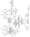
- FIG.1 Japanese Patent Laid-open JP-A-60157586 depicted in FIG.1 was proposed.
- a color original 2 is stuck onto a rotary input drum 1.
- the color original 2 is spottily image-outputted onto a recording material or a color paper 11 stuck onto a rotary output drum 10. This image-outputting is based on the information which has been graphic-inputted by a digitizer 14 serving as a graphic input device.
- the color original 2 is spottily scanned by a read head 21 and is thereby color-separated.
- Color separation signals CS obtained by reading the image information are inputted to a logarithmic converting circuit 3.
- the logarithmic converting circuit 3 converts the color separation signals CS into density signals DN. Thereafter, the density signals DN are converted into digital signals DS in an A/D converter 4.
- the digital density signals DS are inputted to a signal processing section 5 and a micro-processor 12 as well.
- the signal processing section 5 performs color processes such as a color correction, sharpness emphasis and a gradation conversion.
- Color-processed image information DSA are converted into analog signals by a D/A converter 6.
- the analog signals are inputted to a modulator 8 incorporated into a laser beam printer. Laser beams emerging from a laser oscillator 7 are modulated.
- the color paper 11 stuck onto the output drum 10 is spottily exposed to the modulated laer beams through an output head (not illustrated).
- a console 16 equipped with a keyboard is prepared as a data/instruction input device.
- the data inputted from the console 16 is further inputted to a computer 13.
- the information processed by the computer 13 is displayed on an interactive type graphic display 15.
- the computer 13 is connected to a microprocessor 12 as a low-order system.
- the density signals DS coming from the A/D converter 4 are inputted to the microprocessor 12 connected to the signal processing section 5.
- An arithmetic operation is effected therein.
- the computer 12 and the microprocessor 12 are combined to constitute a computer system.
- An instruction to the operator is displayed on the graphic display 15 in accordance with a program incorporated therein. Positions of the input and output drums 1 and 10 are detected by an unillustrated detector.
- the positional information thereof is inputted to a motion control section 9.
- the motion control section 9 is connected to the microprocessor 12 so that the control unit 9 relatively drive-controls a positional relation between the input drum 1 and the output drum 10.
- the digitizer 14 has an X-Y axis and original point coordinates intrinsic to the device.
- the digitiser 14 is capable of moving the original point to an arbitrary point by signal processing and easily rotating the coordinates.
- a corresponding relation between the digitizer 14 and the position of image on the input drum 1 is established by providing guides such as pins in a plurality of common positions.
- the digitizer 14 is connected to the computer 13, whereby an image configuration and desired positional coordinates can be inputted.
- the image input/output system described above has the following defects.
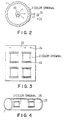
- the color original 2 is stuck directly to the cylindrical input drum 1 formed of an acrylic resin, glass or the like to have a smooth transparent surface.
- the color original 2 is irradiated with the light emerging from a light source 20 provided inwardly of the input drum 1.
- Transmitted light from the color original 2 is received by a read head 21, whereby an image of the original 2 is inputted,
- a gap equivalent to a wave length of light of the light source 20 is formed between the color original 2 and the input drum 1.
- Newton's ring interference fringes
- Newton's ring appears as a fringe-like ununiformity in density on the color original 2, resulting in a remarkable in quality of the original.
- the prevent such interference fringes powders of hyperfine particles have higherto been spread between the color original 2 and the input drum 1, or alternatively fillers have been applied therebetween.
- the powders have such defects that the particles become visible when increasing the image magnification, and the powders are hard to be dealt with.
- the fillers also have defects, wherein it is troublesome to apply and wipe off the fillers.
- the image input/output system such as a total color scanner is arranged as follows. Ths system inputs the image information of an original film or the like. After performing enlargement/reduction thereof, the image information is outputted in an arbitrary layout. The original is read in the same way with the case of FIG. 2. In the image input/output system, however, it is required to known the coordinates of the color original 2 on the input drum 1 when reading the original for the layout. For this purpose, in the prior art, as illustrated in FIG. 3, the color original 2 is stuck onto a transparent rectangular sheet-like original sticking base 22 having a thickness of 100 ⁇ m by use of sticking tapes 23. Corresponding pins of the digitizer are fitted in positioning holes 24.
- the coordinates of a necessary portion of the color original 2 are inputted to the image input/output system. Thereafter, as depicted in FIG. 4, corresponding pins 25 of the input drum 1 are fitted in positioning holes 22 formed in the base 22, thus attaching the base.
- the color original 2 is, as in the same way with the case of FIG.2, irradiated with the light emerging from the light source 20 provided inwardly of the input drum 1.
- the read head 21 receives the transmitted light LT travelling from the color original 2. An image of the color original is thereby inputted.
- the layout process is effected with a correspondence to the coordinates inputted by the digitizer.
- the conventional color scanner requires a skillful operator to determine the separating conditions. Besides, the time for determining the separating conditions is longer than the time for which the scanner actually rotates. Furthermore, the conventional color scanner is intricate in operation, and a psychological load on the operator of the scanner is large.
- a color sepration scanner has been developed to obviate the defects incidental to the above-described drum type color scanner.
- This color separation scanner performs the process by reading the color original by a plane scanning method with a TV camera.
- This type of scanner also presents problems in terms of a speed-up of the reading process and an efficiency as well.
- An additional problem is that setting of the processing conditional parameters is troublesome.
- a quality preference mode selectable by the user to achieve different dot resolutions is for example described in GB-A-2 109 192.
- the troublesome or original sticking process is eliminated.
- Rough prescanning and fine main scanning are carried out in time series.
- Prescan data is stored and then displayed.
- Made are contrivances in terms of placement of slits and image outputting as well.
- the productivity of preparing prints is thereby improved.
- a quality preference mode which can be indicated as the necessity arises is also provided.
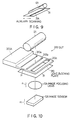
- FIG.5 illustrates an external configuration of an image processing system of this invention.
- the image processing system includes a color scanner 100, disposed at the center, for processing an image by reading an original image. Formed in an upper portion of the color scanner 100 is a cassette insert port 101 for inserting an original cassette which accommodates a color original.
- a desk 201 is positioned in the vicinity of the color scanner 100. Placed on the desk 201 are a mouse 203 and a keyboard 202 by which the operator inputs necessary data and instructions to a data input apparatus 200.
- a CRT 204 for displaying the necessary information and the original image in a picture frame divided mode is provided upwardly of the desk 201.
- An output unit 500 outputs a halftone film on the basis of the data processed by a signal processing unit 400 incorporated into the scanner 100, which will be mentioned later.
- the output unit 500 is installed in close proximity to the scanner 100.
- an automatic developing unit 600 for developing a process film outputted from the output unit 500.
- a speed preference mode, a photosensitive material consumption mode, a quality preference mode are indicated through the keyboard 202 or the mouse 203. Note that the placement of the respective system units is not limited to the one depicted in FIG.5.
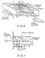
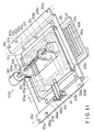
- FIG.6 shows a structure of an original table 110 of an image reader unit of the color scanner 100.
- the whole original table 110 assuming a box-like shape is scanned in auxiliary scan directions by use of a movable member 111 connected to the original table 110 in combination with a wire 112 and a motor 113.
- the wire 112 and the motor are connected to this movable member 111.
- the original table 110 accommodates a rotary board receiver 115 rotated by a motor 114 in illustrated directions.
- a cassette receiver 116 for receiving an original cassette 30 is provided at the center of the rotary board receiver 115.
- the rotary board receiver 116 as a whole is scanned in trimming directions by a movable member 117 connected to a movement plate 130 thereof in combination with a wire 118 and a motor 119.
- the wire 118 and the motor 119 are connected to the movable member 117.
- the movable members 111 and 117 may involve the use of a screw rod and a nut for scanning.
- An upper surface of an onset portion of the original table 110 in the auxiliary scanning direction is formed with a transparent correction region 131 for correcting shading of an optical system by reading a fundamental optical quantity at a read starting time of prescan.
- the correction region 131 serves as a home position in the auxiliary scanning directions. At the start of scanning, an image sensor is capable of detecting just the correction region 131.
- rotary board receiver 115 Aligned on an upper surface of the rotary board receiver 115 are guide rollers 140-142 and 143-145 for carrying the original cassette 30 so as to hold two sides of the original cassette 30. A top end of the guide roller is provided with a stopper 132 for positioning the original cassette 30. Besides, appropriate positions of the original cassette 30 are marked with symbols (not illustrated) for indicating a size and an ID number of the original to be accommodated. Those symbols are read by a detector till the original cassette 30 is inserted and loaded into the cassette receiver 116.
- FIG.7 schematically illustrates a structure of an interior of an input section 150 of the color scanner 100.
- the original cassette 30 is carried onto a carrier passageway via the cassette insert port 101 of the input section 150.
- Carrier rollers 152-154 are arranged aside and upwardly of the carrier passageway 151.
- Driving rollers 155-157 are attached via driving shafts to the carrier rollers 152-154.
- a belt 162 is stretched between the driving rollers 155-157 and a driving shaft 161 of a motor 160.
- the motor rotationally drives the carrier roller 152-154.
- the original cassette 30 is thereby carried on the carrier passageway 151 while being guided.
- the original cassette 30 thus carried is further sent and loaded into the original table 110 fully illustrated in FIG.6.
- FIG.8 depicts an optical system of the input unit of the scanner 100.
- the original cassette 30 loaded into the cassette receiver 116 is irradiated with light of a line aperture type fluorescent lamp 121 placed upwards via a flare preventive slit 300 which will be mentioned later.
- the original cassette 30 houses a color original 31 such as color reversal film of 35 mm, Brownie or a size of 4" ⁇ 4.
- the color original 31 is held by a pair of reflection preventive transparent glasses 32 and 33 for holding the original.
- Image light traveling through the slit 300 and the original cassette 30 is inputted to image focusing lens 124 each having a predetermined magnification.
- the image light is further inputted to a color separation prism 125 connected to a lower part of the image focusing lens 124.
- the image light is thereby separated into three primary colors R, G and B.
- the three color-separated beams R, G and B are inputted to image sensors (126R, 126G, 126B) each composed of a CCD or the like. Those beams are converted into picture signals PS of RGB.
- the plurality of image focusing lens 124 prepared therein are changeable into a lens system having a predetermined magnification by use of a turret.
- FIG.9 shows a scanning relation between the fluorescent lamp 121 and the color original 31. Linear main scanning lines 31A are read simultaneously and scanned in the auxiliary scanning directions, thus reading an entire image.
- the variable-width slit is formed between the fluorescent lamp 121 and the original 31 (original cassette 30 ) to prevent the flare of the optical system.
- the slit having the least width is set per reading/scanning operation within a range where a predetermined light quantity is satisfied.
- FIG.10 is a perspective view showing one example of a position adjusting mechanism of the slit 300. Slits 310a, 310b and 310c each having a different slit width are formed. Disposed in a predetermined position between the fluorescent lamp 121 and the original 31 is a light blocking plate 310 movable in arrowed directions P with the aid of a slit position adjusting mechanism 300A.
- a matting black coating e.g.
- FIG. 11 is a schematic perspective view showing one example of the slit position adjusting mechansim 300A.
- FIG.12 is a sectional view taken substantially along the line X-X thereof.
- Fixed onto the light blocking plate 310 is a slider 302 slidable along two guide rods 301a and 301b placed in parallel to the moving direction P of the light blocking plate 310.
- Fixed onto the slider 302 is a nut 303 of a ball screw disposed in parallel to the moving direction P of the light blocking plate 310.
- a baseplate 304 is provided with a predetermined gap so as not to contact an opposite surface of the slider 302 to the foregoing fixing surface.
- the baseplate 304 is disposed so that the nut 303 of the ball screw protrudes from an opening 304A formed in the baseplate 304. Both ends of guide rods 301a and 301b are fixedly supported on support members 305a and 305b fixed to one surface ( on the side of the slider 302 ) of the baseplate 304.
- a pulse motor 307 rotates a male screw 306 screwed into the nut 303 of the ball screw.
- Bearings 308a and 308b retain the male screw 306.
- the pulse motor 307 and the bearings 308a and 308b are fixed to the other surface of the baseplate 304. Only the baseplate 304 is fixed to a baseplate 309 fixed to a machine board 350.
- inclination adjusting means 311 Fixed to the baseplate 309 is an inclination adjusting means 311 having side surfaces into which screws 330a and 330b are screwed.
- One end of an inclination adjusting lever 312 is positioned between the screws 330a and 330b of the inclination adjusting means 311.
- the other end of the inclination adjusting lever 312 is fixed to the baseplate 304 so as not to contact the inclination adjusting means 311.
- an adjustment of a slit position involves the following steps. Positioning pins 322a and 322b provided on the machine board 350 are fitted into positioning holes 321a and 321b holed in the baseplate 309. The baseplate 309 is thus positioned and thereafter fixed to the machine board 350. A hole 325 is formed in the baseplate 304 mounted with the light blocking plate 310. Fitted into the hole 324 is an inclination adjusting pin 325 provided on the baseplate 309. The baseplate 304 is thus temporarily positioned. The light blocking plate 310 is moved by driving the pulse motor 307, thereby positioning a desired slit on the optical axis. The image light, the configuration of which is linearly transformed via the slit 300, is inclined to the image sensor 126.
- one of screws 330a and 330b of the inclination adjusting means 311 is slackened, whereas the other is fastened.
- the inclination adjusting lever 312, the baseplate 304 and the light blocking plate 310 gyrate about the inclination adjusting pin 325.
- An inclination of the image light linearly transformed via the slit 300 can be set to zero.
- the thus positioned baseplate 304 is fixed to the baseplate 309 with fixing screws 326a, 326b, 326c and 326d. With this arrangement, the image light linearly transformed via the slit 300 can be incident on an appropriate position of the image sensor 126.
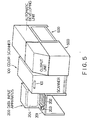
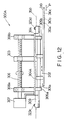
- FIG.13 schematically illustrates a construction of the output unit 500.
- the output unit 500 works as a slave of a signal processing unit 400 of the scanner 100.
- the output unit 500 executes control sequences constant with respect to a command transferred by an interface RS-232C.
- the output unit 500 sends back a resultant status to a CPU 401, serving as a host, of the signal processing unit 400. More specifically, when transmitting a status check signal to the output unit 500 from the CPU 401, the output unit 500, if in a possible-of-exposure state, sends a "ready" signal. Subsequently, the output unit sends back an "OK" signal in response to an exposure-ready inquiry signal transmitted from the CPU 401. An exposure is then effected.
- the picture signal coming from the signal processing unit 400 undergoes halftone processing in a halftoning circuit 531 which will be mentioned later.
- the picture signal is thereby converted into an ON/OFF signal.
- a photosensitive material 503 is exposed to a laser beam 502 emitted from a laser shaping light source 501 consisting of laser diodes.
- a main scanning of the laser beam 502 involves the use of a resonant scanner 504.
- the photosensitive material 503 on an auxiliary scanning drum 510 is exposed to the laser beam, by which the main scanning has been performed, therough an f ⁇ lens 505 and a mirror 506 as well.
- the auxiliary scanning drum 510 carries out an auxiliary scanning with respect to the laser beam 502.
- the drum is rotated by a DC servo motor under PLL control.
- the photosensitive material 503 is housed in a photosensitive magazine 511.
- the photosensitive material 503 is carried while passing above the auxiliary scanning drum 510 through a carrier roller.
- the photosensitive material 503 is cut off to predetermined lengths by a cutter 512 and then discharged.
- Halftone processing is based on a digital system in which the picture signals are sequentially compared with a set of 8-bit thresholds (halftone data).
- the halftone data are, if standard, stored in an ROM.
- the data other than the above-mentioned are loaded from a floppy disk provided as an option.
- the output unit 500 acts invariably as a slave for the signal processing unit 400.
- the output unit 500 has only the functions to execute the sequences constant with respect to the command coming from the RS-232C and send back the resultant status. Therefore, the output unit 500 does not start the communications at all.
- the signal processing unit 400 manages the output unit 500 through communications, thereby performing a series of sequences during the exposure.
- the output unit 500 further incorporates functions which can be started from a panel of the signal processing unit 400, these functions including initial load, cleaning, cutting and setting of a photosensitive material residual quantity register.
- the initial load is herein defined as a process to cut and initialize, in the case of mounting the photosensitive magazine 511 or operning the cover due to an occurrence of jam, the portion at which the light strikes on the photosensitive material 503 just when being fed to a predetermined position ( the material is irradiated with the light ).
- Cleaning is defined as a process to resupply a developper, a fixing solution and washing water.
- This process requires the steps of pulling out a predetermined amount of photosensitive material 503, cutting the material, thereafter feeding the material to the automatic developing unit 600 and operating the automatic developing unit 600.
- Cutting is conceived as a process to cut and discharge the photosensitive material 503 pulled out for exposure.
- Setting of the photosensitive material residusal quantity register is a function effected as follows. A residual quantity of the photosensitive material 503 is set when mounting the photosensitive material magazine 511. The residual quantity is subtracted every time cutting and discharging are carried out. The subtracted value is displayed.
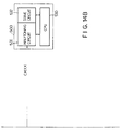
- FIG.14 depicts an internal configuration of the color scanner 100.
- RGB picture signals outputted from the image sensors 126R, 126G, 126B of the optical system 120 of the input unit of the scanner 100.
- the RGB picture signals are A/D converted and inputted to the signal processing unit 400.
- the signal processing unit 400 includes the CPU (host computer) 401 for controlling the whole.
- the CPU 401 effects an equivalent neutral density (END) conversion 402, a color correction 403, an enlargement or reduction 404, a sharpness emphasis 405, a gradation conversion 406 and a black printer generation 407 as the necessity arises.
- END equivalent neutral density
- a color correction 403 effects an enlargement or reduction 404, a sharpness emphasis 405, a gradation conversion 406 and a black printer generation 407 as the necessity arises.
- Connected to the CPU 401 are a floppy disk 410 and a hard disk 411 which the necessary data are read from or stored in.
- Prescan data which has undergone the END conversion, is stored in a memory 408.
- a data input apparatus 200 is connected via the CPU 401 to the signal processing unit 400.
- Photoengraving signals of four colors such as C, M, Y, K (black) are transmitted to the output unit 500.
- Laser beam 502 are emitted to the laser shaping light source 501 via the halftoning circuit 531 and the drive circuit 532.
- the halftoning circuit 531 and the drive circuit 532 within the output unit 500 are controlled by a CPU 501.
- the user of the image processing system employs the keyboard 202 or the mouse 203 to indicate a speed preference mode, a photosensitive material consumption preference mode and a quality preference mode.
- the speed preference mode is intended to lessen (reduce) the time (the number of scannings ) of main scan by the scanner 100 to the greatest possible degree.
- the consumption preference mode is intended to decrease as much consumption of the photosensitive material 503 as possible.
- the quality preference mode is to set both the original cassette 30 and the placement of output image to enhance a read resolution of the scanner 100 with resepct to the color original 31.
- a memory 408 incorporates a blanking management table 408A which will be mentioned later.
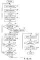
- the original cassette 30 is inserted from the cassette insert port 101 and set in an original read unit within the scanner 100 (Step S1).
- the original cassette 30 is, however, automatically intruded into a cassette receiver 116.
- the original table 110 is carried to the home position. At this moment, the symbols put on the original cassette 30 are read to discern an original size, an ID number and an original pattern.
- the optical system remains in the home position.
- the rough prescan is automatically started from the home position of the correction region 131 (Step S2).
- the correction region 131 of the original table 110 is at first read.
- the signal processing unit 400 calculates and sets the correction data about shading or the like.
- a thinning-out rate, a scanning velocity and a read range are set in accordance with the read original size information.
- the home position of the optical system serves as an optical magnification for effecting the prescan.
- the prescan is carried out invariable with a constant optical magnification irrespective of the original size.
- Th prescan data conceived as image data read by thinning-out are END-converted within the signal processing unit 400.
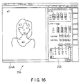
- the resultant data are stored in the memory 408 and at the same time, as illustrated in FIG.16, displayed on the CRT 204 of the data input apparatus 200 (Step S3).
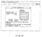
- an existence and non-existence of the color original 31 within the original cassette 30 are displayed as illustrated in FIG.17 (a mark ⁇ indicates the existence of the original, whereas a mark ⁇ indicates the non-existence thereof).
- FIG.17 shows an example where one cassette contains six originals. The discernment is made when a plurality of originals is settable in one cassette.
- Read from the memory 408 is data within a region defined by 10 ⁇ 10 pixels in lengthwise/crosswize directions.
- Image processing arithmetic at a plurality of arbitrary points of the image displayed is simulated.
- the simulation result is displayable on a display column 205.
- a simulation result at an indicating point ⁇ 1 of FIG.16 corresponds to "l" of the display column.
- a simulation result at an indicating point ⁇ 2 corresponds to "2”.
- a simulation result at an indicating point ⁇ 3 corresponds to "3".
- the display of the display column is rewritable in real time concomitant with a change in the image processing conditions.
- the original cassette 30 accommodates, as depicted in FIG.18A, one sheet of original having a size of 4" ⁇ 5".
- the cassette 30 accommodates two sheets of originals in Brownie and 6 sheets of originals of 35 m/m. Images of the respective originals are electrically enlarged by the signal processing unit 400 to maximize the resolution on the display part 204A of the CAT 204. The enlarged images are displayed as shown in FIG.9. The image in a trimming range defined by diagonal points Q1, Q2 is displayed in enlargement. The optical magnification during the main scan is automatically varied corresponding to the trimming range set on the prescan image. The original table 110 is thereby moved in the main scanning direction.
- Step S4 Inputted and set by means of the data input apparatus 200 are data on trimming, magnification and, if necessary, other data on the number of output lines, negative/positive and rotary angle (Step S4). Those data should invariably be set per original.
- a set-up mode (automatic, manual) of conditional parameters needed for image processing (Step S5). If the automatic mode is selected, the conditional parameters are automatically set based on the prescan data stored in the memory 408 (Step S7). The conditional parameters are displayed on the right display part of the CAT 204. Whereas of the manual mode is selected, the conditional parameters are manually inputted through the keyboard 301 (Step S6) An output of the prescan image is simulated with the aid of the set image processing conditions.
- the simulation result is displayed in the display column 205.
- the conditional parameters are set referring to the results.
- the conditional parameters are set based on the image data stored in the memory 408 by the prescan. In consequence of this step, the original cassette 30 (or the original) is removable out of the system during the set-up.
- the conditional parameters includes a coefficient value for correcting the color, sharpness coefficients for sharpness enphasis and an inclination of gradation conversion.
- Automatic setting by prescan is effected by methods disclosed in, e.g., Japanese Patent Laid-open Nos.111569/1987 and 111570/1987 made by the present applicant.
- Step S10 the read part is returned to the home position (Step S8), and the next cassette is loaded. Whether the prescan is effected or not is judged (Step S10). If the next cassette is not loaded, the image of the color original 31 of the original cassette 30 which has been inputted is read in accordance with an indication of main scan (Step S11). In this case, however, the original cassette 30 is rotated by the rotary board receiver 115. Subsequently, the cassette 30 is moved by the movable member 117 in the trimming directions and by the movable member 111 in the auxiliary scanning directions. A region of a line 31A shown in FIG.7 undergoes the main scan (Step S12). In the main scan.
- the main scan information is transferred to the input section 120 of the scanner 100, the signal processing unit 400 and the output unit 500. An instruction to start the main scan is thus given.
- the optical system moves to a necessary optical magnification position.
- the correction region 131 is read to calculate and set the correction data.
- the indicated read range is subjected to the main scanning process. More specifically, the light, which has been emitted from the fluorescent lamp 121 and has penetrated, is inputted to the image focusing lens 124.
- the light is color-separated into RGB by means of the color separation prism 125. Images of the color-separated beams are formed on the image sensors 126A, 126G and 126B.
- the picture signals PS for detected one line are outputted from the image sensor 126R, 126G and 126B.
- the picture signals PS are inputted to the signal processing unit 400.
- the signal processing unit 400 performs the processes such as the END conversion 402, the color correction 403, the enlargement or reduction 404, the sharpness emphasis 405, the gradation conversion 406 and the black printer generation 407.
- the color correction is herein carried out by a method disclosed in, e.g., Japanese Patent Laid-open No. 178355/1983.
- the sharpness emphasis is effected by amethod disclosed in, e.g., Japanese Patent Laid-open No. 54570/1985.
- the END conversion and the gradation conversion inclusive may be performed by a method disclosed in Japanese Patent Laid-open No. 11062/1984.
- Step S12 The foregoing main scan is effected (Step S12), through this will be stated later in relation to the previously indicated speed preference mode, the photosensitive material consumption preference mode and the quality preference mode.
- the output unit 500 outputs the image (Step S13).
- a size of the photosensitive material 503 employed in the output machine 500 is set beforehand in the blanking management table 408A.
- Sent to the output unit 500 are printing plate signals of C, M, Y, K which are obtained in the signal processing unit 400 by processing the image data of the main scan.
- the printing plate signals undergo halftone processing in the halftoning circuit 531.
- the thus processed signals are transmitted to the drive circuit 532 of the laser shaping light source 501, wherein beams are emitted with binary signals of dot outputs.
- the laser beams 502 emitted from the light source 501 are inputted to the resonant scanner 504 and the f ⁇ lens 505.
- the laser beams 502 are reflected by the mirror 506.
- the photosensitive material 503 is exposed to the laser beams at a position of the auxiliary scanning drum 510.
- the exposed photosensitive material 503 is cut off to predetermined lengths by the cutter 512.
- the cut materials are transferred to the automatic developing unit 600, wherein the development is performed to prepare 4-color printing plate of C, M, Y, K. After finishing the main scan and setting of condiions of all the originals, an instruction to eject the original cassette 30 is given.
- the original cassette 30 is thereby automatically carried and ejected from the cassette insert port 101.
- FIG.20 herein shows time relations between the prescan, setting of conditions and main scan with respect to originals #1 through #4.
- the main scan of the original, in which setting of conditions has been finished, is effected completely in parallel to setting of conditions of the next original.
- the speed preference mode, the photosensitive material consumption preference mode and the quality preference mode can be indicated beforehand.
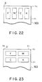
- the speed preference mode is, however, intended to reduce as much scanning time as possible. In the case of outputting four plates of YMCK, it is enough to effect scanning once on an output pattern depicted in FIG.22. Based on an output pattern of FIG.23, however, scanning has to be performed twice. Eventually, if follows that the output pattern of FIG.22 is faster than the latter.
- the speed preference mode is a mode to automatically select and output the pattern possible of output at a high speed.
- the photosensitive material consumption preference mode is intended to decrease as much consumption of the photosensitive material 503 as possible.
- the output pattern of FIG.23 is smaller in Y 1 than the output pattern of FIG.22.
- the photosensitive material consumption preference mode is set to automatically select and output the output pattern on which the consumption of the photosensitive material 503 is reduced to the greatest possible degree.
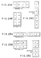
- the four printing plates of YMCK are outputted.
- FIGs. 24A to 24C depict lengthwise patterns (patterns #1 - #3).
- FIGs.25A to 25C illustrate crosswise patterns (patterns #4 - #6). Those two types of patterns are selectable corresponding to the output size.
- the management as to whether those patterns #1 - #6 can be outputted or not is made by use of the blanking management table 408A within the memory 408. Note that in this embodiment, the four plates of YMCK are outputted, but two or three or even one color may be available.
- the quality preference mode is a mode to enhance the quality of the output image by increasing the read resolution power of the scanner 100 with respect to the original 31 in the input section 150.
- the resolution power is higher in a relation between the original 31 and the image sensor 126 of FIG.26B than in a relation between the original 31 and the image sensor 126 of FIG.26A. For this reason, when setting the quality preference mode, the short sides of the original 31 are read by main scanning.
- the lengthwise patterns #1 - #3 of FIGs.24A to 24C are used as output patterns.
- the user selects any one of the speed preference mode and the photosensitive material consumption preference mode. The user further makes a decision of whether the quality preference mode is adopted or not.
- the quality preference mode is not necessarily indicated.
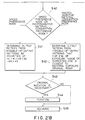
- the trimming range is, as in the previous case, at first inputted (Step S20).
- the output magnification is inputted from the data input apparatus 200 (Step S21).
- the ouput sizes for the respective patterns #1 - #8 are calculated (Step S22).
- the calculation of the output sizes requires the following steps. All of resist works and a train of characters are added. Thereafter, a rectangular region defined by the output size of x ⁇ y is obtained when outputting the plates of YMCK, this region containing all the plates of YMCK. If a plurality of exposure processes are carried out, the calculation is made adding an interval of exposure units adjacent in a direction y .
- Step S23 Thereafter, whether the quality preference mode is indicated or not is judged (Step S23). If indicated, the short sides of the original 31 are read by the main scanning. The output patterns are therefore limited to the lengthwise patterns. Referring to the blanking management table 408A, whetehr or not the patterns #1-#3 can be outputted is judged (Steps S30, S31). Whereas if not, whether or not all the patterns #1 - #6 can be outputted is judged referring to the blanking management table 408A (Steps S32, S33). In any case, whether the possible-of-output patterns exist or not is judged (Steps S34, S35). If there is not possible-of-output pattern, an error comes out. The blanking management table 408A stores, though this will be stated later, the statuses up to the last output together with the size of the photosensitive material. It is therefore feasible to judge whether outputting is possible or not from the sizes of the patterns #1 - #6.
- Step S40 If it is judged at the Steps S34, S35 that the possible-of-output patterns exist, there is made a judgement as to whether or not the speed preference mode or the photosensitive material consumption preference mode is indicated (Step S40). If the speed preference mode is indicated, the output pattern is determined from the possible-of-output patterns according to the following priorities: pattern #4 > pattern #1 > pattern #5 > pattern #2 > pattern #6 > pattern #3 (Step S41). In this case, if the scanning time (the number of scannings) is the same, there is taken such a pattern that the top end (Y 1 in FIGs.22 and 23) of the printing plate to be ouputted in the closest to a photosensitive material exposure original point 0 (see FIGs.22 and 23). If the photosensitive material consumption preference mode is indicated, the output pattern is determined from the possible-of-output patterns, wherein the top end Y 1 in the exposure range of the outputted one is the closest to the photosensitive material exposure original point 0 (Step S42)
- the blanking management table 408A herein stores the output statuses up to the last output.
- This table 408A also stores y-coordinates, x-onset coordinates ⁇ S, x-terminal coordinates ⁇ E and a possible-of-output width W ⁇ .
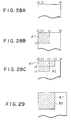
- the initial status shown in FIG. 28A is expressed by Table 1 because of outputting nothing yet.
- Table 1 y ⁇ S ⁇ E W ⁇ 0 0 W W -1
- "-1" in Table 1 indicates a terminator
- W represents the exposure width in the main scanning direction
- y denotes the width in the auxiliary scanning direction
- thE width "y” being set so as not to exceed an exposure length.
- an output pattern AZ is outputted.
- the possible-of-output ranges of the y-coordinates of the onset and of the terminal of the outputted exposure range are changed. If there is not element of the y-coordinates of the terminal, the elements are newly prepared. The elements are inserted in the array so as not to disorder the ascending sequence of the y-coordinates. In the case of changing the possible-of-output range, as illustrated in FIG.29, the interval of the adjacent exposusre units is added.
- the symbol B1 of FIG.29 indicates an output size calculated at the Step S22.
- the symbol B2 indicates an output size for modifying the blanking management table 408A, whether or not the patterns #1 - #3 are possible of output is judged at the Steps S30 and S31.
- the pattern is determined at the Step S41 according to the following priorities: pattern #4 > pattern #1 > pattern #5 > pattern #2 > pattern #6.
- the Step S42 there is obtained the pattern in which the top end of the exposure range is the closest to the photosensitive material original point 0.
- FIG.30 shows a calculation algorithm of the output positions of the respective patterns.
- “Ph” is the exposure length in the auxiliary scanning direction
- "Pw” is the exposure length in the main scanning direction of the pattern
- the blaking management table 408A are expressed by yi , XSi, XEi, Wi.
- the output pattern is, as depicted in FIG.29, set at the left uppermost portion. Note that in the case of 4-colors (3-colors, 2-colors) outputting, if all the plates (4 plates in the case of 4-color ouptputting) can not be outputted an bloc within the maximum exposure size, divisional outputting is effected.
- Step S43 If necessary, the original is rotated (Step S44). Scanning is then performed (Step S45).
- the output size is calculated by inputting the trimming and the magnification.
- the magnification may be calculated by inputting the trimming range upon inputting the output size.
- a physical trimming range (Xa, Ya) on the original is calculated by inputting the trimming range.
- the output size inputted is expressed by (Xb, Yb).
- a main scanning magnification is calculated by Xb/Xa, while an auxiliary scanning magnification is calculated by Yb/Ya.
- the original is read by a transmissive method.
- the configuration may, however, be based on a reflective method; or the input units based on these two methods are provided in combination and employed by a circuitwise changeover.
- the image processing system of this invention exhibits the following advantages.
- the system is of the cassette type which requires no sticking of the original.
- the operation is therefore simple.
- the high-speed input is possible because of the input method based on the plane scanning. It is feasible to improve an availability factor of the scanner.
- the original is read by the prescan and main scan.
- the conditional parameter are set based on the stored prescan data, and at the same time the image is displayed.
- the image is processed based on the main scan data, and ouputting is then effected.
- the productivity in operation is remarkably improved.
- the image processing system of this invention is provided with the speed preference mode, photosensitive material consumption preference mode and quality preference mode which are to be indicated by the user. It is therefore possible to obtain an efficient and rational working situation.
Landscapes
- Engineering & Computer Science (AREA)
- Multimedia (AREA)
- Signal Processing (AREA)
- Facsimile Scanning Arrangements (AREA)
- Preparing Plates And Mask In Photomechanical Process (AREA)
- Facsimile Image Signal Circuits (AREA)
- Editing Of Facsimile Originals (AREA)
Description
- This invention is directed to a high-speed and high efficiency image processing system of a plane scanning type. This invention relates more particularly to an image processing system arranged as follows. A color original is read by rough prescanning, the read data is stored, conditional parameters are set, and the color original is read by fine main scanning and processed. An image of the color original is efficiently recorded on a photosensitive material, thus preparing a printing plate. Besides, there can be selected either a speed preference mode to reduce a scanning time or a photosensitive material consumption preference mode to decrease consumption of the photosentitive material. Independently of these modes, there can be indicated a quality preference mode to enhance an output by increasing a read resolution in an input unit.
- The following is a description of a conventional method of preparing color separations. A plurality of color originals are laid out per color separation. For this purpose, a halftone color separation film is prepared with a predetermined magnification by use of a color scanner. A mask plate prepared by a separate process and the halftone color separation film are allocated on a layout sheet, and each original is stuck. Contact exposure is then effected, thereby preparing a laid-out color separation. This method, however, presents the following defects. This method is large in the number of processes and also complicated. A highly skillful technique is required, wherein the color separation is disposed in the neighborhood of a predetermined position and stuck onto the layout sheet. A good deal of time, labors and materials are also needed. The plurality of color originals are color-printed at specified magnifications. The prepared duplicated original is cut out into a predetermined block copy pattern. The pattern is stuck in a predetermined position of a block copy layout sheet. A laid-out color image is then copied. This method is, however, based on a photographic technique. It is therefore impossible to freely change a color correction process, a sharpness emphasis and a gradation conversion process. This is a problem in terms of an image quality. Besides, a system ( e.g., Japanese Patent Publication JP-B-62016035) for simultaneously layout-outputting rectangular images by a plurality of input devices has the following defects. It is hard to correspond to arbitrary graphics. Preparation of the mask plate requires the labors. Inputting of the color originals needs a plurality of input scanning units.
- In recent years, there has been proposed a layout retouch system known as a so-called total system in the process of preparing prints. In this system, the graphic is inputted by a digitizer. The graphic and an image (pictorial pattern) are displayed on a color CRT. The color original is, however, scanned at a spefified magnification by a color scanner. After effecting an A/D conversion, the color original information is stored in a storage unit. The color original information stored therein is displayed on the color CRT in accordance with the input graphic information. Editing is carried out within a main storage unit of a computer by an interactive input. The information is stored again in a magnetic disk or the like in a format corresponding to the output picture. Subsequently, the color image information corresponding to the output picture after being edited undergoes a D/A conversion. The thus converted information is thereafter inputted to an output control circuit of the color scanner. A desired layout image is thereby obtained. There arise, however, the following defects inherent in the layout retouch system described above. A large capacity storage medium is needed for storing the information on the color originals. A high-speed computer is also required for the editing process. The system construction is very costly. The editing process also takes a large amount of time.
- To obviate those defects, an image input/output system (Japanese Patent Laid-open JP-A-60157586) depicted in FIG.1 was proposed. A color original 2 is stuck onto a
rotary input drum 1. The color original 2 is spottily image-outputted onto a recording material or acolor paper 11 stuck onto arotary output drum 10. This image-outputting is based on the information which has been graphic-inputted by adigitizer 14 serving as a graphic input device. The color original 2 is spottily scanned by a readhead 21 and is thereby color-separated. Color separation signals CS obtained by reading the image information are inputted to alogarithmic converting circuit 3. Thelogarithmic converting circuit 3 converts the color separation signals CS into density signals DN. Thereafter, the density signals DN are converted into digital signals DS in an A/D converter 4. The digital density signals DS are inputted to asignal processing section 5 and a micro-processor 12 as well. Thesignal processing section 5 performs color processes such as a color correction, sharpness emphasis and a gradation conversion. Color-processed image information DSA are converted into analog signals by a D/A converter 6. The analog signals are inputted to amodulator 8 incorporated into a laser beam printer. Laser beams emerging from alaser oscillator 7 are modulated. Thecolor paper 11 stuck onto theoutput drum 10 is spottily exposed to the modulated laer beams through an output head (not illustrated). - On the other hand, a
console 16 equipped with a keyboard is prepared as a data/instruction input device. The data inputted from theconsole 16 is further inputted to acomputer 13. The information processed by thecomputer 13 is displayed on an interactive typegraphic display 15. Thecomputer 13 is connected to amicroprocessor 12 as a low-order system. The density signals DS coming from the A/D converter 4 are inputted to themicroprocessor 12 connected to thesignal processing section 5. An arithmetic operation is effected therein. Note that thecomputer 12 and themicroprocessor 12 are combined to constitute a computer system. An instruction to the operator is displayed on thegraphic display 15 in accordance with a program incorporated therein. Positions of the input andoutput drums motion control section 9. Themotion control section 9 is connected to themicroprocessor 12 so that thecontrol unit 9 relatively drive-controls a positional relation between theinput drum 1 and theoutput drum 10. Thedigitizer 14 has an X-Y axis and original point coordinates intrinsic to the device. Thedigitiser 14 is capable of moving the original point to an arbitrary point by signal processing and easily rotating the coordinates. A corresponding relation between thedigitizer 14 and the position of image on theinput drum 1 is established by providing guides such as pins in a plurality of common positions. Thedigitizer 14 is connected to thecomputer 13, whereby an image configuration and desired positional coordinates can be inputted. - The image input/output system described above, however, has the following defects. When reading the original, as illustrated in FIG. 2, the
color original 2 is stuck directly to thecylindrical input drum 1 formed of an acrylic resin, glass or the like to have a smooth transparent surface. Thecolor original 2 is irradiated with the light emerging from alight source 20 provided inwardly of theinput drum 1. Transmitted light from thecolor original 2 is received by aread head 21, whereby an image of the original 2 is inputted, In this case, if a gap equivalent to a wave length of light of thelight source 20 is formed between the color original 2 and theinput drum 1. Newton's ring (interference fringes) is caused due to interference action of the light between the underside of thecolor original 2 and the surface of theinput drum 1. Newton's ring appears as a fringe-like ununiformity in density on thecolor original 2, resulting in a remarkable in quality of the original. The prevent such interference fringes, powders of hyperfine particles have higherto been spread between the color original 2 and theinput drum 1, or alternatively fillers have been applied therebetween. The powders have such defects that the particles become visible when increasing the image magnification, and the powders are hard to be dealt with. The fillers also have defects, wherein it is troublesome to apply and wipe off the fillers. - The image input/output system such as a total color scanner is arranged as follows. Ths system inputs the image information of an original film or the like. After performing enlargement/reduction thereof, the image information is outputted in an arbitrary layout. The original is read in the same way with the case of FIG. 2. In the image input/output system, however, it is required to known the coordinates of the color original 2 on the
input drum 1 when reading the original for the layout. For this purpose, in the prior art, as illustrated in FIG. 3, thecolor original 2 is stuck onto a transparent rectangular sheet-likeoriginal sticking base 22 having a thickness of 100 µm by use of stickingtapes 23. Corresponding pins of the digitizer are fitted in positioning holes 24. The coordinates of a necessary portion of the color original 2 are inputted to the image input/output system. Thereafter, as depicted in FIG. 4, correspondingpins 25 of theinput drum 1 are fitted in positioning holes 22 formed in thebase 22, thus attaching the base. Thecolor original 2 is, as in the same way with the case of FIG.2, irradiated with the light emerging from thelight source 20 provided inwardly of theinput drum 1. The readhead 21 receives the transmitted light LT travelling from thecolor original 2. An image of the color original is thereby inputted. The layout process is effected with a correspondence to the coordinates inputted by the digitizer. - The conventional color scanner requires a skillful operator to determine the separating conditions. Besides, the time for determining the separating conditions is longer than the time for which the scanner actually rotates. Furthermore, the conventional color scanner is intricate in operation, and a psychological load on the operator of the scanner is large.
- A color sepration scanner has been developed to obviate the defects incidental to the above-described drum type color scanner. This color separation scanner performs the process by reading the color original by a plane scanning method with a TV camera. This type of scanner also presents problems in terms of a speed-up of the reading process and an efficiency as well. An additional problem is that setting of the processing conditional parameters is troublesome.
- In the image processing systems including the conventional color scanner and image input/output system, there is given no consideration to show what kind of status the original may assume when reading the image. This is the real situation. For this reason, a big loss in consumption of the photosensitive material is caused depending on the original reading directions. In addition, a large utility of the scan reading time of the input original is also produced. The user of the image processing system therefore demands for changing the output quality by increasing the read resolving power in the input unit.
- A quality preference mode, selectable by the user to achieve different dot resolutions is for example described in GB-A-2 109 192.
- It is an object of the present invention, which has been devised under such circumstances, to provide an image processing system exhibiting the following characteristics. The troublesome or original sticking process is eliminated. It is possible to automatically or manually set image processing conditions base on automatic analysis of original data with a good operability. Rough prescanning and fine main scanning are carried out in time series. Prescan data is stored and then displayed. Made are contrivances in terms of placement of slits and image outputting as well. The productivity of preparing prints is thereby improved. Provided are a speed preference mode and a photosensitive material consumption preference mode which are appropriately selectable by the user. A quality preference mode which can be indicated as the necessity arises is also provided.
- This object can be achieved, according to the invention with the features of
independent claim 1. - The nature, principle and utility of the invention will become more apparent from the following detailed description when read in conjunction with the accompanying drawings.
- In the accompanying drawings:
- FIG.1 is a block diagram showing one example of a conventional image input/output system;
- FIGs.2 through 4 are diagrams of assistance in explaining a color original stuck onto an input drum:
- FIG.5 is a sketch drawing showing one embodiment of this invention;
- FIG.6 is a view showing one example of an original board of this invention;
- FIG.7 is a diagram illustrating a mechanism for loading an original cassette;
- FIG.8 is a diagram depicting an optical system of an image input unit;
- FIG.9 is a diagram showing a relation between a light source and an original;
- FIG.10 is a view illustrating a principle structure of slits employed in this invention;
- FIG.11 is a view showing a driving mechanism thereof;
- FIG.12 is a structural sectional view taken substantially along the line X-X of FIG.11;
- FIG.13 is a diagram showing one example of an output unit;
- FIG.14 is a block diagram illustrating a circuit system of this invention;
- FIG.15 is a flow chart showing an operating example of this invention;
- FIG.16 is an example representation of a display;
- FIG.17 is a representation of a display example, showing an existence and non-existence of the original;
- FIGs.18A and 18B are diagrams showing examples of accommodating the original in the original cassette;
- FIG.19 is a diagram of assistance in explaining the representation on a picture;
- FIG.20 is a chart showing relations between prescan, setting of conditions and main scan;
- FIG.21 is a flow chart showing an operating example of this invention;
- FIGs.22 and 23 are diagrams each showing a relation between output patterns and a photosensitive material;
- FIGs.24A to 24C and 25A to 25C are diagrams showing examples of the output patterns;
- FIGs.26A and 26B are diagrams of assistance in explaining a read resolution;
- FIG.27 is a diagram of assistance in explaining an output size;
- FIGs.28A to 28C and FIG.29 are diagrams of assistance in explaining a blanking management table; and
- FIG.30 is a flow chart showing a method of determining an output position of the pattern.
- FIG.5 illustrates an external configuration of an image processing system of this invention. The image processing system includes a
color scanner 100, disposed at the center, for processing an image by reading an original image. Formed in an upper portion of thecolor scanner 100 is acassette insert port 101 for inserting an original cassette which accommodates a color original. Adesk 201 is positioned in the vicinity of thecolor scanner 100. Placed on thedesk 201 are amouse 203 and akeyboard 202 by which the operator inputs necessary data and instructions to adata input apparatus 200. ACRT 204 for displaying the necessary information and the original image in a picture frame divided mode is provided upwardly of thedesk 201. Anoutput unit 500 outputs a halftone film on the basis of the data processed by a signal processing unit 400 incorporated into thescanner 100, which will be mentioned later. Theoutput unit 500 is installed in close proximity to thescanner 100. There is also provided an automatic developingunit 600 for developing a process film outputted from theoutput unit 500. A speed preference mode, a photosensitive material consumption mode, a quality preference mode are indicated through thekeyboard 202 or themouse 203. Note that the placement of the respective system units is not limited to the one depicted in FIG.5. - FIG.6 shows a structure of an original table 110 of an image reader unit of the
color scanner 100. The whole original table 110 assuming a box-like shape is scanned in auxiliary scan directions by use of amovable member 111 connected to the original table 110 in combination with awire 112 and amotor 113. Thewire 112 and the motor are connected to thismovable member 111. The original table 110 accommodates arotary board receiver 115 rotated by amotor 114 in illustrated directions. Acassette receiver 116 for receiving anoriginal cassette 30 is provided at the center of therotary board receiver 115. Therotary board receiver 116 as a whole is scanned in trimming directions by amovable member 117 connected to amovement plate 130 thereof in combination with awire 118 and amotor 119. Thewire 118 and themotor 119 are connected to themovable member 117. Note that themovable members transparent correction region 131 for correcting shading of an optical system by reading a fundamental optical quantity at a read starting time of prescan. Thecorrection region 131 serves as a home position in the auxiliary scanning directions. At the start of scanning, an image sensor is capable of detecting just thecorrection region 131. Aligned on an upper surface of therotary board receiver 115 are guide rollers 140-142 and 143-145 for carrying theoriginal cassette 30 so as to hold two sides of theoriginal cassette 30. A top end of the guide roller is provided with astopper 132 for positioning theoriginal cassette 30. Besides, appropriate positions of theoriginal cassette 30 are marked with symbols (not illustrated) for indicating a size and an ID number of the original to be accommodated. Those symbols are read by a detector till theoriginal cassette 30 is inserted and loaded into thecassette receiver 116. - On the other hand, FIG.7 schematically illustrates a structure of an interior of an
input section 150 of thecolor scanner 100. Theoriginal cassette 30 is carried onto a carrier passageway via thecassette insert port 101 of theinput section 150. Carrier rollers 152-154 are arranged aside and upwardly of thecarrier passageway 151. Driving rollers 155-157 are attached via driving shafts to the carrier rollers 152-154. Abelt 162 is stretched between the driving rollers 155-157 and a drivingshaft 161 of a motor 160. The motor rotationally drives the carrier roller 152-154. Theoriginal cassette 30 is thereby carried on thecarrier passageway 151 while being guided. Theoriginal cassette 30 thus carried is further sent and loaded into the original table 110 fully illustrated in FIG.6. - FIG.8 depicts an optical system of the input unit of the
scanner 100. Theoriginal cassette 30 loaded into thecassette receiver 116 is irradiated with light of a line aperturetype fluorescent lamp 121 placed upwards via a flarepreventive slit 300 which will be mentioned later. Theoriginal cassette 30 houses a color original 31 such as color reversal film of 35 mm, Brownie or a size of 4" × 4. Thecolor original 31 is held by a pair of reflection preventivetransparent glasses slit 300 and theoriginal cassette 30 is inputted to image focusinglens 124 each having a predetermined magnification. The image light is further inputted to acolor separation prism 125 connected to a lower part of theimage focusing lens 124. The image light is thereby separated into three primary colors R, G and B. The three color-separated beams R, G and B are inputted to image sensors (126R, 126G, 126B) each composed of a CCD or the like. Those beams are converted into picture signals PS of RGB. Note that the plurality ofimage focusing lens 124 prepared therein are changeable into a lens system having a predetermined magnification by use of a turret. FIG.9 shows a scanning relation between thefluorescent lamp 121 and thecolor original 31. Linearmain scanning lines 31A are read simultaneously and scanned in the auxiliary scanning directions, thus reading an entire image. - In accordance with this invention, the variable-width slit is formed between the
fluorescent lamp 121 and the original 31 ( original cassette 30 ) to prevent the flare of the optical system. The slit having the least width is set per reading/scanning operation within a range where a predetermined light quantity is satisfied. FIG.10 is a perspective view showing one example of a position adjusting mechanism of theslit 300.Slits fluorescent lamp 121 and the original 31 is alight blocking plate 310 movable in arrowed directions P with the aid of a slitposition adjusting mechanism 300A. A matting black coating ( e.g. , brand name: Sunday Paint (Dai-Nippon Toryo Co., Ltd) ) is coated or printed on the surface of thelight blocking plate 310. Hence, an optical magnification of the image is varied by moving theimage sensor 126 and theimage focusming lens 124 in arrowed directions m and n in the figure. In this case, thelight blocking plate 310 is shifted in the arrowed direction P by the slitposition adjusting mechanism 300A. The slit having the list width suited to the present optical magnification is positioned on the optical axis. A clear image is thereby obtained. - FIG. 11 is a schematic perspective view showing one example of the slit
position adjusting mechansim 300A. FIG.12 is a sectional view taken substantially along the line X-X thereof. Fixed onto thelight blocking plate 310 is aslider 302 slidable along twoguide rods light blocking plate 310. Fixed onto theslider 302 is anut 303 of a ball screw disposed in parallel to the moving direction P of thelight blocking plate 310. Moreover, abaseplate 304 is provided with a predetermined gap so as not to contact an opposite surface of theslider 302 to the foregoing fixing surface. Thebaseplate 304 is disposed so that thenut 303 of the ball screw protrudes from anopening 304A formed in thebaseplate 304. Both ends ofguide rods support members baseplate 304. Apulse motor 307 rotates amale screw 306 screwed into thenut 303 of the ball screw.Bearings male screw 306. Thepulse motor 307 and thebearings baseplate 304. Only thebaseplate 304 is fixed to abaseplate 309 fixed to amachine board 350. Other members ( e.g., the light blocking plate 210, theslider 302 and the like ) do not contact thebaseplate 309. Fixed to thebaseplate 309 is an inclination adjusting means 311 having side surfaces into which screws 330a and 330b are screwed. One end of aninclination adjusting lever 312 is positioned between thescrews inclination adjusting lever 312 is fixed to thebaseplate 304 so as not to contact the inclination adjusting means 311. - Based on the above construction, an adjustment of a slit position involves the following steps.
Positioning pins machine board 350 are fitted intopositioning holes baseplate 309. Thebaseplate 309 is thus positioned and thereafter fixed to themachine board 350. Ahole 325 is formed in thebaseplate 304 mounted with thelight blocking plate 310. Fitted into thehole 324 is aninclination adjusting pin 325 provided on thebaseplate 309. Thebaseplate 304 is thus temporarily positioned. Thelight blocking plate 310 is moved by driving thepulse motor 307, thereby positioning a desired slit on the optical axis. The image light, the configuration of which is linearly transformed via theslit 300, is inclined to theimage sensor 126. At this time, one ofscrews inclination adjusting lever 312, thebaseplate 304 and thelight blocking plate 310 gyrate about theinclination adjusting pin 325. An inclination of the image light linearly transformed via theslit 300 can be set to zero. The thus positionedbaseplate 304 is fixed to thebaseplate 309 with fixingscrews slit 300 can be incident on an appropriate position of theimage sensor 126. - FIG.13 schematically illustrates a construction of the
output unit 500. Theoutput unit 500 works as a slave of a signal processing unit 400 of thescanner 100. Theoutput unit 500 executes control sequences constant with respect to a command transferred by an interface RS-232C. Theoutput unit 500 sends back a resultant status to aCPU 401, serving as a host, of the signal processing unit 400. More specifically, when transmitting a status check signal to theoutput unit 500 from theCPU 401, theoutput unit 500, if in a possible-of-exposure state, sends a "ready" signal. Subsequently, the output unit sends back an "OK" signal in response to an exposure-ready inquiry signal transmitted from theCPU 401. An exposure is then effected. The picture signal coming from the signal processing unit 400 undergoes halftone processing in ahalftoning circuit 531 which will be mentioned later. The picture signal is thereby converted into an ON/OFF signal. Aphotosensitive material 503 is exposed to alaser beam 502 emitted from a laser shapinglight source 501 consisting of laser diodes. A main scanning of thelaser beam 502 involves the use of aresonant scanner 504. Thephotosensitive material 503 on anauxiliary scanning drum 510 is exposed to the laser beam, by which the main scanning has been performed, therough anfθ lens 505 and amirror 506 as well. Theauxiliary scanning drum 510 carries out an auxiliary scanning with respect to thelaser beam 502. The drum is rotated by a DC servo motor under PLL control. Thephotosensitive material 503 is housed in aphotosensitive magazine 511. Thephotosensitive material 503 is carried while passing above theauxiliary scanning drum 510 through a carrier roller. Thephotosensitive material 503 is cut off to predetermined lengths by acutter 512 and then discharged. - Halftone processing is based on a digital system in which the picture signals are sequentially compared with a set of 8-bit thresholds (halftone data). The halftone data are, if standard, stored in an ROM. The data other than the above-mentioned are loaded from a floppy disk provided as an option. The
output unit 500 acts invariably as a slave for the signal processing unit 400. Theoutput unit 500 has only the functions to execute the sequences constant with respect to the command coming from the RS-232C and send back the resultant status. Therefore, theoutput unit 500 does not start the communications at all. - Based on the above configuration, the signal processing unit 400 manages the
output unit 500 through communications, thereby performing a series of sequences during the exposure. Theoutput unit 500 further incorporates functions which can be started from a panel of the signal processing unit 400, these functions including initial load, cleaning, cutting and setting of a photosensitive material residual quantity register. The initial load is herein defined as a process to cut and initialize, in the case of mounting thephotosensitive magazine 511 or operning the cover due to an occurrence of jam, the portion at which the light strikes on thephotosensitive material 503 just when being fed to a predetermined position ( the material is irradiated with the light ). Cleaning is defined as a process to resupply a developper, a fixing solution and washing water. This process requires the steps of pulling out a predetermined amount ofphotosensitive material 503, cutting the material, thereafter feeding the material to the automatic developingunit 600 and operating the automatic developingunit 600. Cutting is conceived as a process to cut and discharge thephotosensitive material 503 pulled out for exposure. Setting of the photosensitive material residusal quantity register is a function effected as follows. A residual quantity of thephotosensitive material 503 is set when mounting thephotosensitive material magazine 511. The residual quantity is subtracted every time cutting and discharging are carried out. The subtracted value is displayed. - FIG.14 depicts an internal configuration of the
color scanner 100. RGB picture signals outputted from theimage sensors optical system 120 of the input unit of thescanner 100. The RGB picture signals are A/D converted and inputted to the signal processing unit 400. The signal processing unit 400 includes the CPU (host computer) 401 for controlling the whole. TheCPU 401 effects an equivalent neutral density (END)conversion 402, acolor correction 403, an enlargement orreduction 404, asharpness emphasis 405, agradation conversion 406 and ablack printer generation 407 as the necessity arises. Connected to theCPU 401 are afloppy disk 410 and a hard disk 411 which the necessary data are read from or stored in. Prescan data, which has undergone the END conversion, is stored in amemory 408. Adata input apparatus 200 is connected via theCPU 401 to the signal processing unit 400. Photoengraving signals of four colors such as C, M, Y, K (black) are transmitted to theoutput unit 500.Laser beam 502 are emitted to the laser shapinglight source 501 via thehalftoning circuit 531 and thedrive circuit 532. Thehalftoning circuit 531 and thedrive circuit 532 within theoutput unit 500 are controlled by aCPU 501. - Based on the construction the operation will be explained with reference to a flow chart of FIG.15. In this case, the user of the image processing system employs the
keyboard 202 or themouse 203 to indicate a speed preference mode, a photosensitive material consumption preference mode and a quality preference mode. The speed preference mode is intended to lessen (reduce) the time ( the number of scannings ) of main scan by thescanner 100 to the greatest possible degree. The consumption preference mode is intended to decrease as much consumption of thephotosensitive material 503 as possible. The quality preference mode is to set both theoriginal cassette 30 and the placement of output image to enhance a read resolution of thescanner 100 with resepct to thecolor original 31. Amemory 408 incorporates a blanking management table 408A which will be mentioned later. - At the first onset, the
original cassette 30 is inserted from thecassette insert port 101 and set in an original read unit within the scanner 100 (Step S1). Theoriginal cassette 30 is, however, automatically intruded into acassette receiver 116. On detecting loading of theoriginal cassette 30, the original table 110 is carried to the home position. At this moment, the symbols put on theoriginal cassette 30 are read to discern an original size, an ID number and an original pattern. - The optical system remains in the home position. When indicating the prescan, the rough prescan is automatically started from the home position of the correction region 131 (Step S2). In this case, the
correction region 131 of the original table 110 is at first read. Based on the read data thereof, the signal processing unit 400 calculates and sets the correction data about shading or the like. A thinning-out rate, a scanning velocity and a read range are set in accordance with the read original size information. Then starts the prescan. The home position of the optical system serves as an optical magnification for effecting the prescan. The prescan is carried out invariable with a constant optical magnification irrespective of the original size. Th prescan data conceived as image data read by thinning-out are END-converted within the signal processing unit 400. The resultant data are stored in thememory 408 and at the same time, as illustrated in FIG.16, displayed on theCRT 204 of the data input apparatus 200 (Step S3). Concurrently with this step, an existence and non-existence of thecolor original 31 within theoriginal cassette 30 are displayed as illustrated in FIG.17 (a mark ○ indicates the existence of the original, whereas a mark × indicates the non-existence thereof). FIG.17 shows an example where one cassette contains six originals. The discernment is made when a plurality of originals is settable in one cassette. Read from thememory 408 is data within a region defined by 10 × 10 pixels in lengthwise/crosswize directions. With the central point of the image data serving as a left upper angle thereof. The data is then sampled. Sampling may be effected for one color data. A means value obtained by sampling at 100 points is compared with a threshold VTH, thereby discerning the existence and non-existence of the original.

display part 204A provided to the left of one picture. In the other right side portion which is not overlapped with this display part, image processing conditions are displayed and inputted. The image display is performed with respect to the original indicated by thekeyboard 202 or themouse 203. Image processing arithmetic at a plurality of arbitrary points of the image displayed is simulated. The simulation result is displayable on adisplay column 205. A simulation result at an indicating point ∗1 of FIG.16 corresponds to "l" of the display column. Similarly, a simulation result at an indicating point ∗2 corresponds to "2". A simulation result at an indicating point ∗3 corresponds to "3". Note that the display of the display column is rewritable in real time concomitant with a change in the image processing conditions. Incidentally, theoriginal cassette 30 accommodates, as depicted in FIG.18A, one sheet of original having a size of 4" × 5". As illustrated in FIG.18B, thecassette 30 accommodates two sheets of originals in Brownie and 6 sheets of originals of 35 m/m. Images of the respective originals are electrically enlarged by the signal processing unit 400 to maximize the resolution on thedisplay part 204A of theCAT 204. The enlarged images are displayed as shown in FIG.9. The image in a trimming range defined by diagonal points Q1, Q2 is displayed in enlargement. The optical magnification during the main scan is automatically varied corresponding to the trimming range set on the prescan image. The original table 110 is thereby moved in the main scanning direction. - Inputted and set by means of the
data input apparatus 200 are data on trimming, magnification and, if necessary, other data on the number of output lines, negative/positive and rotary angle (Step S4). Those data should invariably be set per original. There is specified a set-up mode (automatic, manual) of conditional parameters needed for image processing (Step S5). If the automatic mode is selected, the conditional parameters are automatically set based on the prescan data stored in the memory 408 (Step S7). The conditional parameters are displayed on the right display part of theCAT 204. Whereas of the manual mode is selected, the conditional parameters are manually inputted through the keyboard 301 (Step S6) An output of the prescan image is simulated with the aid of the set image processing conditions. The simulation result is displayed in thedisplay column 205. The conditional parameters are set referring to the results. The conditional parameters are set based on the image data stored in thememory 408 by the prescan. In consequence of this step, the original cassette 30 (or the original) is removable out of the system during the set-up. The conditional parameters includes a coefficient value for correcting the color, sharpness coefficients for sharpness enphasis and an inclination of gradation conversion. Automatic setting by prescan is effected by methods disclosed in, e.g., Japanese Patent Laid-open Nos.111569/1987 and 111570/1987 made by the present applicant. - After executing the preprocess described above, the read part is returned to the home position (Step S8), and the next cassette is loaded. Whether the prescan is effected or not is judged (Step S10). If the next cassette is not loaded, the image of the
color original 31 of theoriginal cassette 30 which has been inputted is read in accordance with an indication of main scan (Step S11). In this case, however, theoriginal cassette 30 is rotated by therotary board receiver 115. Subsequently, thecassette 30 is moved by themovable member 117 in the trimming directions and by themovable member 111 in the auxiliary scanning directions. A region of aline 31A shown in FIG.7 undergoes the main scan (Step S12). In the main scan. the main scan information is transferred to theinput section 120 of thescanner 100, the signal processing unit 400 and theoutput unit 500. An instruction to start the main scan is thus given. The optical system moves to a necessary optical magnification position. Then, thecorrection region 131 is read to calculate and set the correction data. The indicated read range is subjected to the main scanning process. More specifically, the light, which has been emitted from thefluorescent lamp 121 and has penetrated, is inputted to theimage focusing lens 124. The light is color-separated into RGB by means of thecolor separation prism 125. Images of the color-separated beams are formed on theimage sensors image sensor END conversion 402, thecolor correction 403, the enlargement orreduction 404, thesharpness emphasis 405, thegradation conversion 406 and theblack printer generation 407. The color correction is herein carried out by a method disclosed in, e.g., Japanese Patent Laid-open No. 178355/1983. The sharpness emphasis is effected by amethod disclosed in, e.g., Japanese Patent Laid-open No. 54570/1985. The END conversion and the gradation conversion inclusive may be performed by a method disclosed in Japanese Patent Laid-open No. 11062/1984. - The foregoing main scan is effected (Step S12), through this will be stated later in relation to the previously indicated speed preference mode, the photosensitive material consumption preference mode and the quality preference mode. After this step, the
output unit 500 outputs the image (Step S13). Note that a size of thephotosensitive material 503 employed in theoutput machine 500 is set beforehand in the blanking management table 408A. Sent to theoutput unit 500 are printing plate signals of C, M, Y, K which are obtained in the signal processing unit 400 by processing the image data of the main scan. The printing plate signals undergo halftone processing in thehalftoning circuit 531. The thus processed signals are transmitted to thedrive circuit 532 of the laser shapinglight source 501, wherein beams are emitted with binary signals of dot outputs. Thelaser beams 502 emitted from thelight source 501 are inputted to theresonant scanner 504 and thefθ lens 505. Thelaser beams 502 are reflected by themirror 506. Thephotosensitive material 503 is exposed to the laser beams at a position of theauxiliary scanning drum 510. The exposedphotosensitive material 503 is cut off to predetermined lengths by thecutter 512. The cut materials are transferred to the automatic developingunit 600, wherein the development is performed to prepare 4-color printing plate of C, M, Y, K. After finishing the main scan and setting of condiions of all the originals, an instruction to eject theoriginal cassette 30 is given. Theoriginal cassette 30 is thereby automatically carried and ejected from thecassette insert port 101. - FIG.20 herein shows time relations between the prescan, setting of conditions and main scan with respect to
originals # 1 through #4. The main scan of the original, in which setting of conditions has been finished, is effected completely in parallel to setting of conditions of the next original. - The operation of the main scan according to this invention will next be described with reference to a flow chart of FIG.21.
- In accordance with this invention, the speed preference mode, the photosensitive material consumption preference mode and the quality preference mode can be indicated beforehand. The speed preference mode is, however, intended to reduce as much scanning time as possible. In the case of outputting four plates of YMCK, it is enough to effect scanning once on an output pattern depicted in FIG.22. Based on an output pattern of FIG.23, however, scanning has to be performed twice. Eventually, if follows that the output pattern of FIG.22 is faster than the latter. The speed preference mode is a mode to automatically select and output the pattern possible of output at a high speed. The photosensitive material consumption preference mode is intended to decrease as much consumption of the
photosensitive material 503 as possible. Supposing that outputting is effected with the same size, the output pattern of FIG.23 is smaller in Y1 than the output pattern of FIG.22. Hence, the consumption of thephotosensitive material 503 is, it can be said, small. The photosensitive material consumption preference mode is set to automatically select and output the output pattern on which the consumption of thephotosensitive material 503 is reduced to the greatest possible degree. According to this invention, the four printing plates of YMCK are outputted. FIGs. 24A to 24C depict lengthwise patterns (patterns #1 - #3). FIGs.25A to 25C illustrate crosswise patterns (patterns #4 - #6). Those two types of patterns are selectable corresponding to the output size. The management as to whether those patterns #1 - #6 can be outputted or not is made by use of the blanking management table 408A within thememory 408. Note that in this embodiment, the four plates of YMCK are outputted, but two or three or even one color may be available. - The quality preference mode is a mode to enhance the quality of the output image by increasing the read resolution power of the
scanner 100 with respect to the original 31 in theinput section 150. The resolution power is higher in a relation between the original 31 and theimage sensor 126 of FIG.26B than in a relation between the original 31 and theimage sensor 126 of FIG.26A. For this reason, when setting the quality preference mode, the short sides of the original 31 are read by main scanning. The lengthwise patterns #1 - #3 of FIGs.24A to 24C are used as output patterns. Note that the user selects any one of the speed preference mode and the photosensitive material consumption preference mode. The user further makes a decision of whether the quality preference mode is adopted or not. The quality preference mode is not necessarily indicated. - When starting the main scan, the trimming range is, as in the previous case, at first inputted (Step S20). The output magnification is inputted from the data input apparatus 200 (Step S21). In accordance with the inputted trimming range and the output magnification, the ouput sizes for the respective patterns #1 - #8 are calculated (Step S22). The calculation of the output sizes requires the following steps. All of resist works and a train of characters are added. Thereafter, a rectangular region defined by the output size of x × y is obtained when outputting the plates of YMCK, this region containing all the plates of YMCK. If a plurality of exposure processes are carried out, the calculation is made adding an interval of exposure units adjacent in a direction y.
- Thereafter, whether the quality preference mode is indicated or not is judged (Step S23). If indicated, the short sides of the original 31 are read by the main scanning. The output patterns are therefore limited to the lengthwise patterns. Referring to the blanking management table 408A, whetehr or not the patterns #1-#3 can be outputted is judged (Steps S30, S31). Whereas if not, whether or not all the patterns #1 - #6 can be outputted is judged referring to the blanking management table 408A (Steps S32, S33). In any case, whether the possible-of-output patterns exist or not is judged (Steps S34, S35). If there is not possible-of-output pattern, an error comes out. The blanking management table 408A stores, though this will be stated later, the statuses up to the last output together with the size of the photosensitive material. It is therefore feasible to judge whether outputting is possible or not from the sizes of the patterns #1 - #6.
- If it is judged at the Steps S34, S35 that the possible-of-output patterns exist, there is made a judgement as to whether or not the speed preference mode or the photosensitive material consumption preference mode is indicated (Step S40). If the speed preference mode is indicated, the output pattern is determined from the possible-of-output patterns according to the following priorities:
pattern # 4 >pattern # 1 >pattern # 5 >pattern # 2 >pattern # 6 > pattern #3 (Step S41). In this case, if the scanning time (the number of scannings) is the same, there is taken such a pattern that the top end (Y1 in FIGs.22 and 23) of the printing plate to be ouputted in the closest to a photosensitive material exposure original point 0 (see FIGs.22 and 23). If the photosensitive material consumption preference mode is indicated, the output pattern is determined from the possible-of-output patterns, wherein the top end Y1 in the exposure range of the outputted one is the closest to the photosensitive material exposure original point 0 (Step S42) - The blanking management table 408A herein stores the output statuses up to the last output. This table 408A also stores y-coordinates, x-onset coordinates × S, x-terminal coordinates × E and a possible-of-output width W×. The initial status shown in FIG. 28A is expressed by Table 1 because of outputting nothing yet.
Table 1 y × S × E W × 0 0 W W -1 Note that "-1" in Table 1 indicates a terminator, "W" represents the exposure width in the main scanning direction, and "y" denotes the width in the auxiliary scanning direction, thE width "y" being set so as not to exceed an exposure length. - An output pattern A1 of FIG.28B is next outputted. Modified in this case are both a possible-of-output range of y-coordinates y = 0 of the onset at which the pattern A1 is outputted and a possible-of-output range of y-coordinates y = y1 of the terminal. These ranges are shown in Table 2.
Table 2 y × S × E W 0 X 1 W W-X1 y1 0 W W -1 - As illustrated in FIG.28C, an output pattern AZ is outputted. Modified are a possible-of-output range of y-coordinates y = 0 of the onset at which the pattern A2 is outputted and a possible-of-output range of y-coordinates y, = y2 of the terminal. These ranges are shown in Table 3.
Table 3 y × S × E W 0 X 1 W W-X2 y2 X 1 W W-X1 y1 0 W W -1 pattern # 4 >pattern # 1 >pattern # 5 >pattern # 2 >pattern # 6. Referring again to the table 408A, at the Step S42, there is obtained the pattern in which the top end of the exposure range is the closest to the photosensitive materialoriginal point 0. - Coordinates ye of the terminal when determining and outputting an output position are calculated with respect to the pattern determined in the manner discussed above. FIG.30 shows a calculation algorithm of the output positions of the respective patterns. In this algorithm, "Ph" is the exposure length in the auxiliary scanning direction, "Pw" is the exposure length in the main scanning direction of the pattern, and the blaking management table 408A are expressed by yi, XSi, XEi, Wi. In association with the possible-of-output region, the output pattern is, as depicted in FIG.29, set at the left uppermost portion. Note that in the case of 4-colors (3-colors, 2-colors) outputting, if all the plates (4 plates in the case of 4-color ouptputting) can not be outputted an bloc within the maximum exposure size, divisional outputting is effected.
- Thereafter, whether the original is required to be rotated or not is judged (Step S43). If necessary, the original is rotated (Step S44). Scanning is then performed (Step S45).
- In accordance with the embodiment discussed above, the output size is calculated by inputting the trimming and the magnification. Alternatively, however, the magnification may be calculated by inputting the trimming range upon inputting the output size. To be more specific, a physical trimming range (Xa, Ya) on the original is calculated by inputting the trimming range. The output size inputted is expressed by (Xb, Yb). A main scanning magnification is calculated by Xb/Xa, while an auxiliary scanning magnification is calculated by Yb/Ya. In the embodiment shown in FIG.4, the original is read by a transmissive method. The configuration may, however, be based on a reflective method; or the input units based on these two methods are provided in combination and employed by a circuitwise changeover.
- The image processing system of this invention exhibits the following advantages. The system is of the cassette type which requires no sticking of the original. The operation is therefore simple. The high-speed input is possible because of the input method based on the plane scanning. It is feasible to improve an availability factor of the scanner. The original is read by the prescan and main scan. The conditional parameter are set based on the stored prescan data, and at the same time the image is displayed. The image is processed based on the main scan data, and ouputting is then effected. The productivity in operation is remarkably improved.
- Besides, the image processing system of this invention is provided with the speed preference mode, photosensitive material consumption preference mode and quality preference mode which are to be indicated by the user. It is therefore possible to obtain an efficient and rational working situation.
- It should be understood that many modifications and adaptations of the invention will become apparent to those skilled in the art and it is intended to encompass such obvious modifications and changes in the scope of the claims appended hereto.
Claims (4)
- An image processing system for preparing halftone films or printing plates by optically reading an original (31) accommodated in an original cassette (30) by plane scanning, properly processing the read image data and thereafter recording said processed data on a photosensitive material (503), comprising means (202,203,204,115) for indicating, selecting and performing a quality preference mode to set said original (31) and placement of output images so as to enhance the scanning resolution of said original (31)
characterized bymeans (202,203,204,408) for indicating, selecting, and performinga speed preference mode by minimizing the number of necessary scans in order to reduce a plane scanning time to the greatest possible degree; ora photosensitive material consumption preference mode by calculating the required length of photosensitive material (503) for possible combinations of the different color representations of said original (31) and minimizing said length by selecting one of the possible combinations in order to decrease consumption of said photosensitive material (503) as much as possible;said means for performing a quality preference mode further comprising means for enhancing the scanning resolution by main scanning the short sides of the originals (31). - processing system as claimed in claim 1,
characterized in that
said printing plates are four plates of CMYK and have lengthwise patterns (#1,#2,#3) or crosswise patterns (#4,#5,#6). - An image processing system as claimed in claim 2,
characterized in that
outputs of said lengthwise patterns (#1,#2,#3) or said crosswise patterns (#4,#5,#6) to the photosensitive material (503) are controlled by a blanking management table. - An image processing system as claimed in any one of claims 1 to 3,
characterized in that
one of said speed preference mode and said photosensitive material consumption preference mode is selected by a user and that said quality preference mode may be optionally selected and performed.
Applications Claiming Priority (2)
| Application Number | Priority Date | Filing Date | Title |
|---|---|---|---|
| JP87660/90 | 1990-04-02 | ||
| JP8766090A JP2607726B2 (en) | 1990-04-02 | 1990-04-02 | Image processing device |
Publications (3)
| Publication Number | Publication Date |
|---|---|
| EP0450552A2 EP0450552A2 (en) | 1991-10-09 |
| EP0450552A3 EP0450552A3 (en) | 1992-07-15 |
| EP0450552B1 true EP0450552B1 (en) | 1997-01-02 |
Family
ID=13921109
Family Applications (1)
| Application Number | Title | Priority Date | Filing Date |
|---|---|---|---|
| EP91105158A Expired - Lifetime EP0450552B1 (en) | 1990-04-02 | 1991-04-02 | Image processing system |
Country Status (4)
| Country | Link |
|---|---|
| US (1) | US5231518A (en) |
| EP (1) | EP0450552B1 (en) |
| JP (1) | JP2607726B2 (en) |
| DE (1) | DE69123868T2 (en) |
Families Citing this family (11)
| Publication number | Priority date | Publication date | Assignee | Title |
|---|---|---|---|---|
| JP2901358B2 (en) * | 1991-02-21 | 1999-06-07 | 富士写真フイルム株式会社 | Image reading device |
| JP3193928B2 (en) * | 1992-06-29 | 2001-07-30 | 株式会社東芝 | Image forming device |
| US5535040A (en) * | 1993-01-12 | 1996-07-09 | Ohtsuka; Tadao | Lens changeable image scanner and lens position control device in the same |
| JPH10173845A (en) | 1996-12-13 | 1998-06-26 | Fuji Photo Film Co Ltd | Image forming device |
| JPH10257273A (en) * | 1997-03-07 | 1998-09-25 | Dainippon Screen Mfg Co Ltd | Image reader |
| JPH1198314A (en) * | 1997-09-17 | 1999-04-09 | Konica Corp | Image reader |
| US6292596B1 (en) * | 1997-09-19 | 2001-09-18 | Eastman Kodak Company | Method for automatic image dependent digitization and processing of small format films |
| DE19832245A1 (en) * | 1998-07-17 | 2000-01-20 | Heidelberger Druckmasch Ag | Procedure to operate image reproduction device, image data detection device, image data processing device, image output and transfer device |
| JP3915430B2 (en) | 2001-04-25 | 2007-05-16 | セイコーエプソン株式会社 | Split printing control |
| EP1667424A3 (en) * | 2001-04-25 | 2007-10-03 | Seiko Epson Corporation | Divisional print control |
| JP5326912B2 (en) * | 2009-07-31 | 2013-10-30 | ブラザー工業株式会社 | Printing device, composite image data generation device, and composite image data generation program |
Family Cites Families (7)
| Publication number | Priority date | Publication date | Assignee | Title |
|---|---|---|---|---|
| US3828319A (en) * | 1969-06-23 | 1974-08-06 | Ipc Service Ltd | Composition system |
| US3800071A (en) * | 1972-04-10 | 1974-03-26 | Hazeltine Corp | Graphic arts process simultation system |
| DE3238509A1 (en) * | 1981-10-19 | 1983-05-05 | Canon K.K., Tokyo | IMAGE RECORDING DEVICE |
| JPS6059864A (en) * | 1983-09-13 | 1985-04-06 | Dainippon Screen Mfg Co Ltd | Picture scanning recording system |
| DE3629462C2 (en) * | 1986-08-29 | 1996-05-15 | Agfa Gevaert Ag | Method and device for electronic image processing with intermediate storage |
| US4882630A (en) * | 1987-06-12 | 1989-11-21 | Sanyo Electric Co., Ltd. | Printing apparatus and facsimile equipment |
| JP2693784B2 (en) * | 1988-07-05 | 1997-12-24 | 株式会社リコー | Image forming device |
-
1990
- 1990-04-02 JP JP8766090A patent/JP2607726B2/en not_active Expired - Fee Related
-
1991
- 1991-03-29 US US07/677,691 patent/US5231518A/en not_active Expired - Lifetime
- 1991-04-02 DE DE69123868T patent/DE69123868T2/en not_active Expired - Fee Related
- 1991-04-02 EP EP91105158A patent/EP0450552B1/en not_active Expired - Lifetime
Also Published As
| Publication number | Publication date |
|---|---|
| JPH03287161A (en) | 1991-12-17 |
| EP0450552A3 (en) | 1992-07-15 |
| DE69123868T2 (en) | 1997-04-30 |
| DE69123868D1 (en) | 1997-02-13 |
| JP2607726B2 (en) | 1997-05-07 |
| EP0450552A2 (en) | 1991-10-09 |
| US5231518A (en) | 1993-07-27 |
Similar Documents
| Publication | Publication Date | Title |
|---|---|---|
| JP2695484B2 (en) | Color scanner | |
| EP0363988B1 (en) | Color scanner and automatic setting method | |
| US5062058A (en) | Image processing method for color scanner | |
| US5202934A (en) | Method of and apparatus for reading image | |
| EP0450552B1 (en) | Image processing system | |
| JPH06311307A (en) | Image forming device | |
| US5436735A (en) | Image forming apparatus to add additional information to original image | |
| US5170267A (en) | Raster input scanner (RIS) with diagnostic mode to predict and verify illumination optical performance | |
| EP0848542B1 (en) | Image forming apparatus | |
| US4788599A (en) | Image processing with image-slant control and/or image-size control | |
| US7034956B2 (en) | Image processing apparatus capable of freely varying aspect ratio, and image forming apparatus using the same | |
| JPS63125954A (en) | Copying device | |
| JP2585754B2 (en) | Image input / output system and signal processing condition setting method | |
| US6384857B2 (en) | Apparatus for forming images, method of controlling the apparatus, and storage medium | |
| US5909537A (en) | Control method for microfilm image reader | |
| US5748341A (en) | Method of and apparatus for determining whether an original is present in a readout region | |
| JP2574021B2 (en) | Image input / output device and method for automatically setting signal processing conditions | |
| JP2575843B2 (en) | Image input / output system and method for automatically setting signal processing conditions | |
| JP2607727B2 (en) | Image processing device having operation history management function | |
| JP2540585B2 (en) | Data management method of color scanner | |
| JP3702692B2 (en) | Print creation method and print creation apparatus | |
| JP2634901B2 (en) | Image processing method of color scanner | |
| JPH07131629A (en) | Image forming device | |
| JPH01227570A (en) | Color scanner | |
| JPS63125953A (en) | Copying device |
Legal Events
| Date | Code | Title | Description |
|---|---|---|---|
| PUAI | Public reference made under article 153(3) epc to a published international application that has entered the european phase |
Free format text: ORIGINAL CODE: 0009012 |
|
| AK | Designated contracting states |
Kind code of ref document: A2 Designated state(s): DE FR GB |
|
| PUAL | Search report despatched |
Free format text: ORIGINAL CODE: 0009013 |
|
| AK | Designated contracting states |
Kind code of ref document: A3 Designated state(s): DE FR GB |
|
| 17P | Request for examination filed |
Effective date: 19921230 |
|
| 17Q | First examination report despatched |
Effective date: 19941207 |
|
| GRAG | Despatch of communication of intention to grant |
Free format text: ORIGINAL CODE: EPIDOS AGRA |
|
| GRAH | Despatch of communication of intention to grant a patent |
Free format text: ORIGINAL CODE: EPIDOS IGRA |
|
| GRAH | Despatch of communication of intention to grant a patent |
Free format text: ORIGINAL CODE: EPIDOS IGRA |
|
| GRAA | (expected) grant |
Free format text: ORIGINAL CODE: 0009210 |
|
| AK | Designated contracting states |
Kind code of ref document: B1 Designated state(s): DE FR GB |
|
| REF | Corresponds to: |
Ref document number: 69123868 Country of ref document: DE Date of ref document: 19970213 |
|
| ET | Fr: translation filed | ||
| PLBE | No opposition filed within time limit |
Free format text: ORIGINAL CODE: 0009261 |
|
| STAA | Information on the status of an ep patent application or granted ep patent |
Free format text: STATUS: NO OPPOSITION FILED WITHIN TIME LIMIT |
|
| 26N | No opposition filed | ||
| REG | Reference to a national code |
Ref country code: GB Ref legal event code: IF02 |
|
| PGFP | Annual fee paid to national office [announced via postgrant information from national office to epo] |
Ref country code: GB Payment date: 20040405 Year of fee payment: 14 |
|
| PGFP | Annual fee paid to national office [announced via postgrant information from national office to epo] |
Ref country code: FR Payment date: 20040421 Year of fee payment: 14 |
|
| PGFP | Annual fee paid to national office [announced via postgrant information from national office to epo] |
Ref country code: DE Payment date: 20040528 Year of fee payment: 14 |
|
| PG25 | Lapsed in a contracting state [announced via postgrant information from national office to epo] |
Ref country code: GB Free format text: LAPSE BECAUSE OF NON-PAYMENT OF DUE FEES Effective date: 20050402 |
|
| PG25 | Lapsed in a contracting state [announced via postgrant information from national office to epo] |
Ref country code: DE Free format text: LAPSE BECAUSE OF NON-PAYMENT OF DUE FEES Effective date: 20051101 |
|
| GBPC | Gb: european patent ceased through non-payment of renewal fee |
Effective date: 20050402 |
|
| PG25 | Lapsed in a contracting state [announced via postgrant information from national office to epo] |
Ref country code: FR Free format text: LAPSE BECAUSE OF NON-PAYMENT OF DUE FEES Effective date: 20051230 |
|
| REG | Reference to a national code |
Ref country code: FR Ref legal event code: ST Effective date: 20051230 |
|
| REG | Reference to a national code |
Ref country code: GB Ref legal event code: 732E |