EP0449727A1 - System and method for actively cooling dry-running gas seals - Google Patents
System and method for actively cooling dry-running gas seals Download PDFInfo
- Publication number
- EP0449727A1 EP0449727A1 EP91400820A EP91400820A EP0449727A1 EP 0449727 A1 EP0449727 A1 EP 0449727A1 EP 91400820 A EP91400820 A EP 91400820A EP 91400820 A EP91400820 A EP 91400820A EP 0449727 A1 EP0449727 A1 EP 0449727A1
- Authority
- EP
- European Patent Office
- Prior art keywords
- seal ring
- gas
- ring carrier
- rotary seal
- rotary
- Prior art date
- Legal status (The legal status is an assumption and is not a legal conclusion. Google has not performed a legal analysis and makes no representation as to the accuracy of the status listed.)
- Granted
Links
- 238000001816 cooling Methods 0.000 title claims description 17
- 238000000034 method Methods 0.000 title claims description 7
- 238000004891 communication Methods 0.000 claims abstract description 15
- 239000012530 fluid Substances 0.000 claims abstract description 15
- 238000007789 sealing Methods 0.000 claims description 7
- 238000013022 venting Methods 0.000 claims 2
- 239000007789 gas Substances 0.000 description 40
- OKTJSMMVPCPJKN-UHFFFAOYSA-N Carbon Chemical compound [C] OKTJSMMVPCPJKN-UHFFFAOYSA-N 0.000 description 2
- 239000000969 carrier Substances 0.000 description 2
- 239000000463 material Substances 0.000 description 2
- 238000011144 upstream manufacturing Methods 0.000 description 2
- 229910052799 carbon Inorganic materials 0.000 description 1
- 239000004020 conductor Substances 0.000 description 1
- 238000010276 construction Methods 0.000 description 1
- 239000000112 cooling gas Substances 0.000 description 1
- 229920001971 elastomer Polymers 0.000 description 1
- 239000000806 elastomer Substances 0.000 description 1
- 238000005516 engineering process Methods 0.000 description 1
- 229910002804 graphite Inorganic materials 0.000 description 1
- 239000010439 graphite Substances 0.000 description 1
- 230000002706 hydrostatic effect Effects 0.000 description 1
- 229910001119 inconels 625 Inorganic materials 0.000 description 1
- 238000012986 modification Methods 0.000 description 1
- 230000004048 modification Effects 0.000 description 1
- 239000003921 oil Substances 0.000 description 1
- HBMJWWWQQXIZIP-UHFFFAOYSA-N silicon carbide Chemical compound [Si+]#[C-] HBMJWWWQQXIZIP-UHFFFAOYSA-N 0.000 description 1
- 229910010271 silicon carbide Inorganic materials 0.000 description 1
- 238000004513 sizing Methods 0.000 description 1
- 229910001220 stainless steel Inorganic materials 0.000 description 1
- 239000010935 stainless steel Substances 0.000 description 1
Images

Classifications
-
- F—MECHANICAL ENGINEERING; LIGHTING; HEATING; WEAPONS; BLASTING
- F16—ENGINEERING ELEMENTS AND UNITS; GENERAL MEASURES FOR PRODUCING AND MAINTAINING EFFECTIVE FUNCTIONING OF MACHINES OR INSTALLATIONS; THERMAL INSULATION IN GENERAL
- F16J—PISTONS; CYLINDERS; SEALINGS
- F16J15/00—Sealings
- F16J15/16—Sealings between relatively-moving surfaces
- F16J15/34—Sealings between relatively-moving surfaces with slip-ring pressed against a more or less radial face on one member
- F16J15/3404—Sealings between relatively-moving surfaces with slip-ring pressed against a more or less radial face on one member and characterised by parts or details relating to lubrication, cooling or venting of the seal
Definitions
- the present invention relates to cooling a dry-running gas seal.
- Dry-running gas seals are a relatively mature technology.
- One of the initial working concepts of dry-running gas seals was provided in U.S. Patent No. 3,499,653 to Gardner . Further refinements which have improved the performance of dry-running gas seals are disclosed, for example, in U.S. Patent Nos. 4,212,475 to Sedy and 4,768,790 to Netzel et al.
- Dry-running gas seals offer the advantage of consuming less power than older oil buffered gas seals.
- gas is a rather poor conductor of heat.
- absolute levels of power generated are small, the temperature buildup in the seal cavity of dry-running gas seals can be great.
- the 3-5 horsepower generated for a seal on a 4 inch shaft operating at 1,000 psig and 16,000 rpm can result in operating temperatures as high as 400°F.
- the present invention overcomes the problems and disadvantages of the prior art by providing a system for cooling the sealing area.
- An object of the invention is to provide a reduction in operating temperature in the seal ring components.
- the invention comprises a dry-running gas seal for sealing a high pressure area from a low pressure area, the seal comprising: a stationary seal ring carrier holding a stationary seal ring; a rotary seal ring carrier holding a rotary seal ring facing the stationary seal ring; and circulating means for capturing a portion of the gas surrounding the rotary seal ring carrier, transferring the captured gas to a heat exchanger for cooling and returning the cooled gas to the high pressure area adjacent to the seal.
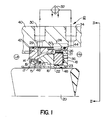
- Figure 1 is a partial cross-sectional view of a dry-running gas seal in accordance with this invention.
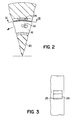
- Figure 2 is a partial cross-sectional view of Section II-II of Fig. 1.
- Figure 3 is a partial view of Section III-III of Fig. 2 showing the stationary seal ring retainer made according to the present invention.
- Figure 4 is a partial cross-section of a rotary seal ring carrier according to the invention.
- Fig. 1 shows a dry-running gas seal 12 of the invention.
- the seal has stationary seal ring carrier 14 with stationary seal ring 16 mounted therein.
- Rotary seal ring carrier 18 is mounted on a shaft 20 and holds the rotary seal ring 22 such that it is facing the stationary seal ring.
- the seal as thus described seals a process gas (indicated by "Hp" in Fig.1) in fluid communication with the radially outer side of the seal from a low pressure area (indicated as "Lp” in Fig. 1) in fluid communication with the radially inner side of the seal.
- Hp process gas
- Lp low pressure area
- the stationary seal ring 16 is preferably made of carbon graphite, although it can be made from other commercially acceptable materials known in the art.
- Stationary seal ring carrier 14, which holds the stationary seal ring in annular pocket 15, is preferably made of Inconel 625 or stainless steel.
- the pocket may be formed by turning or other methods well known in the art.
- a series of holes 17 are bored into the bottom of the pocket. Springs 19 fit into those bore holes and serve to engage the stationary seal ring with the rotary seal ring when the seal is not pressurized.
- the stationary seal ring carrier 14 is fixed to a housing 40 by conventional means, for example "O" rings 42 and 44 are positioned at the rear and front of the stationary seal ring carrier and form a seal between the stationary seal ring carrier 14 and housing 40.
- An "O" ring 46 similarly forms a seal between the stationary seal ring carrier 14 and the seal ring 16.
- the primary flow path for any gas leakage is between the faces of stationary seal ring 16 and rotary seal ring 22.
- the rotary seal ring 22 is preferably made of silicon carbide, although it can be made from other commercially acceptable materials known in the art.
- the rotary seal ring is held in the pocket 23 of the rotary seal ring carrier 18 by an annular "L" shaped clip 21 (shown beat in Fig. 4) which press fits against the outer portion of the pocket.
- the rotary seal ring carrier 18 fits over shaft 20 and includes an "O" ring 48 which forms a seal between the shaft and the carrier 18.
- the face of the rotary seal ring has spiral grooves formed thereon.
- the grooves serve to provide both hydrostatic and hydrodynamic forces for separating The sealing faces. When exposed to a pressurized gas, the gas enters the grooves and provides an opening force. That opening force is balanced by the gas pressure acting on the back of the stationary seal ring 16, which pressure tends to close the sealing faces.
- the grooves preferably have a average groove angle of 5-15° or 60-85° and extend from the outer periphery across 50-70% of the sealing face. The inventors have found that the above groove angles and sizing of the grooves provide optimum results.
- the seal includes circulating means for cooling the gas surrounding the seal.
- the circulating means includes an extension 24 of the stationary seal ring carrier 14 which extends the carrier over the rotary seal ring carrier 18.
- the extension contains a plurality of apertures 25 preferably having flow pickup scoops 26 formed at each aperture, one of which is shown in Fig. 3.
- the scoops promote the capture of the gas at the apertures.
- the apertures and scoops are preferably uniformly spaced about the circumference of the extension 24.
- annular pocket or recess 50 is formed between the axially intermediate portion of the stationary seal ring carrier 14 and the adjacent inner wall of housing 40.
- This recess 50 is positioned between "O" rings 42 and 44.
- the forward or upstream portion of the recess 50 is positioned opposite the outer circumference of the rotary ring carrier 18 and the rotary ring 22.
- the plurality of apertures 25, which are preferably aligned with the outer surface of the rotary seal ring carrier 18, are in fluid communication with the annular recess 50.
- Annular recess 50 in turn is in fluid communication with exhaust bore 30 formed in housing 40.
- Exhaust bore 30 is in fluid communication with heat exchanger 32, which in turn is in fluid communication with return bore 34 formed in the housing 40.
- Return bore 34 is formed upstream of recess 50 and rotary ring carrier 18. In the preferred embodiment, the return bore 34 is positioned immediately adjacent the rotary carrier 18.
- these elements provide a flow path for gas to flow through apertures 25, recess 50, exhaust bore 30, heat exchanger 32 and return bore 34.
- the relatively hot gas at the interface between the carrier 14 and carrier 18 is cooled and returned to the sealed high pressure area.
- the heat exchanger may be of conventional design as known in the art, for example, a shell and tube heat exchanger (available commercially from Exergy, Inc. and other sources).
- the rotary carrier 18 and seal ring 22 rotate at high speeds relative to the housing 40 and stationary seal ring carrier 14 and seal ring 16. This high speed rotation causes the gas at the interface between carrier 18 and carrier 14 to move in the interface.
- the average velocity of the gas in the clearance between the rotary seal ring retainer and the stationary seal ring retainer extension is approximately one-half the velocity of the outside diameter of the rotating seal ring carrier. This means that for a 6 inch O.D. rotary seal ring retainer rotating at 16,000 rpm with a O.D. circumferential speed of approximately 420 feet per second, a gas velocity of approximately 200 feet per second is created.
- the scoops 26 and apertures 25 capture a portion of the dynamic head, i.e., the pressure equivalent of the energy of motion.
- This dynamic head for a 200 ft. per second velocity with air at 1000 psi produces approximately a 20 psi pressure increase between the recess 50 within the extension 24 and the process gas "Hp".
- the pressure is sufficient to flow the gas in recess 50 through exhaust bore 30 to a heat exchanger 32 where the gas is cooled and then returned through return bore 34 to a position close to the back of the rotary seal ring retainer.
- a circulation of cooling gas to the back of stationary seal ring 16 may be provided by gas flow through orifice 29 formed in carrier 14 and preferably aligned with conduit 30. Orifice 29 causes a portion of the gas that would normally flow from recess 50 through exhaust bore 30 to flow behind the stationary seal ring. Although the gas passing through this orifice has not yet passed through the heat exchanger, a measure of cooling is still provided because the gas in the seal cavity has been cooled by the heat exchanger and is cooler than in a conventional dry-running gas seal.
- the rotary seal ring retainer includes a series of holes 36 formed in the back in order to circulate the cooled gas around the rotary seal ring. These holes are slanted toward the direction of rotation at an angle of 35° to 45° from the plane of rotation. This orientation pumps gas into and around the back of the rotary seal ring and out vent holes 52 which are provided in the side of the rotary seal ring carrier.
- 6 to 8 holes 36 are provide which are circular in cross-section with a 1/4 to 3/8 inch diameter.
- vent openings may be provided in the axially orthogonal part of the "L" shaped spring clip 21 which serves, along with finger spring 54, to retain the rotary seal ring 21 in pocket 23.
- the vent holes allow pocket 23 to have a flow path 58 for the gas because the rotary seal ring is spaced from the seal ring carrier so that flow may enter at holes 36 ("in") and exit at holes 52 ("out”).
- "O" ring 56 prevents the gas entering holes 36 from leaking past the seal.
- Cooling the seal cavity results in increased seal face flatness, improved elastomer life (e.g., "O" ring life) and minimizes the problems associated with differential thermal expansion between the seal rings and their carriers.
- elastomer life e.g., "O" ring life
- the apertures 25 and scoops 26 are formed in the stationary carrier. This embodiment is preferred since the system can be adapted to a seal environment by simply placing bores 30 and 34 in the housing at the seal. It should be apparent to those skilled in the art, however, that a plurality of apertures and flow channels could be formed in the housing.
Landscapes
- Engineering & Computer Science (AREA)
- General Engineering & Computer Science (AREA)
- Mechanical Engineering (AREA)
- Mechanical Sealing (AREA)
- Motor Or Generator Cooling System (AREA)
- Sealing Using Fluids, Sealing Without Contact, And Removal Of Oil (AREA)
Abstract
Description
- The present invention relates to cooling a dry-running gas seal.
- Dry-running gas seals are a relatively mature technology. One of the initial working concepts of dry-running gas seals was provided in U.S. Patent No. 3,499,653 to Gardner. Further refinements which have improved the performance of dry-running gas seals are disclosed, for example, in U.S. Patent Nos. 4,212,475 to Sedy and 4,768,790 to Netzel et al.
- Dry-running gas seals offer the advantage of consuming less power than older oil buffered gas seals. However, gas is a rather poor conductor of heat. Thus, although absolute levels of power generated are small, the temperature buildup in the seal cavity of dry-running gas seals can be great. For example, the 3-5 horsepower generated for a seal on a 4 inch shaft operating at 1,000 psig and 16,000 rpm can result in operating temperatures as high as 400°F.
- Increased temperature buildup causes reduced "O" ring life and increased differential thermal growth between the seal rings and their carriers.
- The present invention overcomes the problems and disadvantages of the prior art by providing a system for cooling the sealing area. An object of the invention is to provide a reduction in operating temperature in the seal ring components.
- Additional objects and advantages of the invention will be set forth in part in the description which follows, and in part will be obvious from the description or may be learned by practice of the invention. The objects and advantages of the invention will be realized and attained by means of the elements and combinations particularly pointed out in the appended claims.
- To achieve the objects and in accordance with the purpose of the invention, as embodied and broadly described herein, the invention comprises a dry-running gas seal for sealing a high pressure area from a low pressure area, the seal comprising: a stationary seal ring carrier holding a stationary seal ring; a rotary seal ring carrier holding a rotary seal ring facing the stationary seal ring; and circulating means for capturing a portion of the gas surrounding the rotary seal ring carrier, transferring the captured gas to a heat exchanger for cooling and returning the cooled gas to the high pressure area adjacent to the seal.
- It is to be understood that both the forgoing general description and the following detailed description are exemplary and explanatory only and are not restrictive of the invention as claimed.
- The accompanying drawings which are incorporated in and constitute part of the specification, illustrate one embodiment of the invention and together with the description serve to explain the principles of the invention.
- Figure 1 is a partial cross-sectional view of a dry-running gas seal in accordance with this invention.
- Figure 2 is a partial cross-sectional view of Section II-II of Fig. 1.
- Figure 3 is a partial view of Section III-III of Fig. 2 showing the stationary seal ring retainer made according to the present invention.
- Figure 4 is a partial cross-section of a rotary seal ring carrier according to the invention.
- Reference will now be made in detail to the presently preferred embodiment of the invention, an example of which is illustrated in the accompanying drawings. Wherever possible the same reference numbers will be used throughout the drawings to refer to the same or like parts.
- Fig. 1 shows a dry-running gas seal 12 of the invention. The seal has stationary
seal ring carrier 14 withstationary seal ring 16 mounted therein. Rotaryseal ring carrier 18 is mounted on ashaft 20 and holds therotary seal ring 22 such that it is facing the stationary seal ring. The seal as thus described seals a process gas (indicated by "Hp" in Fig.1) in fluid communication with the radially outer side of the seal from a low pressure area (indicated as "Lp" in Fig. 1) in fluid communication with the radially inner side of the seal. - The
stationary seal ring 16 is preferably made of carbon graphite, although it can be made from other commercially acceptable materials known in the art. Stationaryseal ring carrier 14, which holds the stationary seal ring inannular pocket 15, is preferably made of Inconel 625 or stainless steel. The pocket may be formed by turning or other methods well known in the art. A series ofholes 17 are bored into the bottom of the pocket. Springs 19 fit into those bore holes and serve to engage the stationary seal ring with the rotary seal ring when the seal is not pressurized. - The stationary
seal ring carrier 14 is fixed to ahousing 40 by conventional means, for example "O"rings 42 and 44 are positioned at the rear and front of the stationary seal ring carrier and form a seal between the stationaryseal ring carrier 14 andhousing 40. An "O"ring 46 similarly forms a seal between the stationaryseal ring carrier 14 and theseal ring 16. As a result, the primary flow path for any gas leakage is between the faces ofstationary seal ring 16 androtary seal ring 22. - The
rotary seal ring 22 is preferably made of silicon carbide, although it can be made from other commercially acceptable materials known in the art. The rotary seal ring is held in thepocket 23 of the rotaryseal ring carrier 18 by an annular "L" shaped clip 21 (shown beat in Fig. 4) which press fits against the outer portion of the pocket. The rotaryseal ring carrier 18 fits overshaft 20 and includes an "O"ring 48 which forms a seal between the shaft and thecarrier 18. - In the embodiment shown, the face of the rotary seal ring has spiral grooves formed thereon. The grooves serve to provide both hydrostatic and hydrodynamic forces for separating The sealing faces. When exposed to a pressurized gas, the gas enters the grooves and provides an opening force. That opening force is balanced by the gas pressure acting on the back of the
stationary seal ring 16, which pressure tends to close the sealing faces. The grooves preferably have a average groove angle of 5-15° or 60-85° and extend from the outer periphery across 50-70% of the sealing face. The inventors have found that the above groove angles and sizing of the grooves provide optimum results. - In accordance with the preferred embodiment of the invention, the seal includes circulating means for cooling the gas surrounding the seal. As embodied herein, the circulating means includes an
extension 24 of the stationaryseal ring carrier 14 which extends the carrier over the rotaryseal ring carrier 18. The extension contains a plurality ofapertures 25 preferably havingflow pickup scoops 26 formed at each aperture, one of which is shown in Fig. 3. The scoops promote the capture of the gas at the apertures. The apertures and scoops are preferably uniformly spaced about the circumference of theextension 24. - As shown in Fig. 1, an annular pocket or
recess 50 is formed between the axially intermediate portion of the stationaryseal ring carrier 14 and the adjacent inner wall ofhousing 40. Thisrecess 50 is positioned between "O"rings 42 and 44. The forward or upstream portion of therecess 50 is positioned opposite the outer circumference of therotary ring carrier 18 and therotary ring 22. The plurality ofapertures 25, which are preferably aligned with the outer surface of the rotaryseal ring carrier 18, are in fluid communication with theannular recess 50.Annular recess 50 in turn is in fluid communication withexhaust bore 30 formed inhousing 40.Exhaust bore 30 is in fluid communication withheat exchanger 32, which in turn is in fluid communication withreturn bore 34 formed in thehousing 40.Return bore 34 is formed upstream ofrecess 50 androtary ring carrier 18. In the preferred embodiment, thereturn bore 34 is positioned immediately adjacent therotary carrier 18. - As will be described below, these elements provide a flow path for gas to flow through
apertures 25, recess 50,exhaust bore 30,heat exchanger 32 andreturn bore 34. The relatively hot gas at the interface between thecarrier 14 andcarrier 18 is cooled and returned to the sealed high pressure area. The heat exchanger may be of conventional design as known in the art, for example, a shell and tube heat exchanger (available commercially from Exergy, Inc. and other sources). - When the seal is operating, the
rotary carrier 18 andseal ring 22 rotate at high speeds relative to thehousing 40 and stationaryseal ring carrier 14 andseal ring 16. This high speed rotation causes the gas at the interface betweencarrier 18 andcarrier 14 to move in the interface. The average velocity of the gas in the clearance between the rotary seal ring retainer and the stationary seal ring retainer extension is approximately one-half the velocity of the outside diameter of the rotating seal ring carrier. This means that for a 6 inch O.D. rotary seal ring retainer rotating at 16,000 rpm with a O.D. circumferential speed of approximately 420 feet per second, a gas velocity of approximately 200 feet per second is created. - The
scoops 26 andapertures 25 capture a portion of the dynamic head, i.e., the pressure equivalent of the energy of motion. This dynamic head for a 200 ft. per second velocity with air at 1000 psi produces approximately a 20 psi pressure increase between therecess 50 within theextension 24 and the process gas "Hp". In accordance with the invention, the pressure is sufficient to flow the gas inrecess 50 through exhaust bore 30 to aheat exchanger 32 where the gas is cooled and then returned through return bore 34 to a position close to the back of the rotary seal ring retainer. - Furthermore, a circulation of cooling gas to the back of
stationary seal ring 16 may be provided by gas flow throughorifice 29 formed incarrier 14 and preferably aligned withconduit 30.Orifice 29 causes a portion of the gas that would normally flow fromrecess 50 through exhaust bore 30 to flow behind the stationary seal ring. Although the gas passing through this orifice has not yet passed through the heat exchanger, a measure of cooling is still provided because the gas in the seal cavity has been cooled by the heat exchanger and is cooler than in a conventional dry-running gas seal. - Preferably, as shown in Figs. 2 and 4, the rotary seal ring retainer includes a series of
holes 36 formed in the back in order to circulate the cooled gas around the rotary seal ring. These holes are slanted toward the direction of rotation at an angle of 35° to 45° from the plane of rotation. This orientation pumps gas into and around the back of the rotary seal ring and out vent holes 52 which are provided in the side of the rotary seal ring carrier. Preferably, 6 to 8holes 36 are provide which are circular in cross-section with a 1/4 to 3/8 inch diameter. As an alternative to the vent holes, vent openings may be provided in the axially orthogonal part of the "L" shapedspring clip 21 which serves, along withfinger spring 54, to retain therotary seal ring 21 inpocket 23. The vent holes allowpocket 23 to have aflow path 58 for the gas because the rotary seal ring is spaced from the seal ring carrier so that flow may enter at holes 36 ("in") and exit at holes 52 ("out"). "O"ring 56 prevents thegas entering holes 36 from leaking past the seal. - Other preferred elements of gas seal design, along with an explanation of gas seal theory, is presented in copending application Serial No. 07/466,652, filed January 17, 1990 and assigned to the same assignee. Copending application Serial No. 07/466,652 is explicitly incorporated herein by reference.
- Cooling the seal cavity results in increased seal face flatness, improved elastomer life (e.g., "O" ring life) and minimizes the problems associated with differential thermal expansion between the seal rings and their carriers.
- In the preferred embodiment shown in the drawings, the
apertures 25 and scoops 26 are formed in the stationary carrier. This embodiment is preferred since the system can be adapted to a seal environment by simply placingbores - It will be apparent to those skilled the art that other modifications and variations can be made in the seal of the present invention and in the construction of this cooling system without departing from the scope or spirit of the invention.
- Other embodiments of the invention will be apparent to those skilled in the art from consideration of the specification and practice of the invention disclosed herein. It is intended that the specification and examples be considered as exemplary only, with the true scope and spirit of the invention being indicated by the following claims.
Claims (9)
- A dry-running gas seal for sealing a high pressure area from a low pressure area, the seal comprising:
a stationary seal ring carrier holding a stationary seal ring;
a rotary seal ring carrier holding a rotary seal ring facing said stationary seal ring; and
circulating means for capturing a portion of the gas surrounding said rotary seal ring carrier, transferring the captured gas to a heat exchanger for cooling and returning the cooled gas to the high pressure area adjacent to the seal. - A dry-running gas seal as claimed in claim 1 wherein said stationary circulating means comprises:
apertures having flow scoops positioned radially outside said rotary seal ring carrier and in fluid communication with the gas surrounding said rotary seal ring carrier;
a heat exchanger in fluid communication with said apertures; and
a return conduit, in fluid communication with said heat exchanger and having a return outlet adjacent to said apertures;
whereby the portion of gas captured by said flow scoops is transferred to and cooled by said heat exchanger. - A dry-running gas seal as claimed in claim 2 wherein a portion of stationary seal ring extends over at least a portion of said rotary seal ring carrier and said apertures are formed in said stationary seal ring carrier.
- An active cooling system for a dry-running gas seal of the type having a stationary seal ring, a stationary seal ring carrier attached to a housing, a rotary seal ring and a rotary seal ring carrier, the active cooling system comprising:
an annular extension of the stationary seal ring carrier adapted for extending over but not contacting the rotary seal ring carrier;
a plurality of apertures formed in said annular extension of the stationary seal ring carrier;
an exhaust bore formed in the housing, said exhaust bore in fluid communication with said apertures;
a heat exchanger in fluid communication with said exhaust bore; and
a return bore formed in the housing, said return bore in fluid communication with said heat exchanger and having a return outlet adjacent said apertures. - An active cooling system as claimed in claim 4 wherein said apertures include scoops extending from said apertures, said scoops extending toward but not contacting the rotary seal ring carrier.
- An active cooling system as claimed in claim 5 wherein said rotary seal ring carrier holds said rotary seal ring in an annular pocket and wherein said system further comprises:
a flow path in said pocket formed between said rotary ring carrier and said rotary seal ring;
at least one hole passing through said rotary seal ring carrier and providing a fluid communication to said flow path adjacent said rotary seal ring, said hole being slanted toward the direction of rotation, whereby gas is drawn toward said rotary seal ring when the rotary seal ring carrier is rotating; and
means for venting said gas from said flow path. - An active cooling system as claimed in claim 6 wherein said means for venting comprises at least one hole in the outer periphery of said flow pocket.
- An active cooling system as claimed in claim 5 further comprising an orifice adapted for allowing fluid communication between said apertures and an area between the back of said stationary seal ring and said stationary seal ring carrier.
- A method of cooling a dry-running gas seal having a stationary seal ring carrier and a rotary seal ring carrier for sealing a process gas within a cavity, the method comprising:
capturing a portion of the gas around the rotary seal ring carrier;
transferring the captured gas to a heat exchanger; cooling the captured gas with the heat exchanger; and returning the cooled gas to the cavity.
Applications Claiming Priority (2)
| Application Number | Priority Date | Filing Date | Title |
|---|---|---|---|
| US50056090A | 1990-03-28 | 1990-03-28 | |
| US500560 | 1990-03-28 |
Publications (2)
| Publication Number | Publication Date |
|---|---|
| EP0449727A1 true EP0449727A1 (en) | 1991-10-02 |
| EP0449727B1 EP0449727B1 (en) | 1996-01-03 |
Family
ID=23989950
Family Applications (1)
| Application Number | Title | Priority Date | Filing Date |
|---|---|---|---|
| EP91400820A Expired - Lifetime EP0449727B1 (en) | 1990-03-28 | 1991-03-26 | System and method for actively cooling dry-running gas seals |
Country Status (4)
| Country | Link |
|---|---|
| EP (1) | EP0449727B1 (en) |
| JP (1) | JP2904956B2 (en) |
| AT (1) | ATE132595T1 (en) |
| DE (1) | DE69115966T2 (en) |
Cited By (1)
| Publication number | Priority date | Publication date | Assignee | Title |
|---|---|---|---|---|
| WO2025122444A1 (en) * | 2023-12-07 | 2025-06-12 | Siemens Energy Global GmbH & Co. KG | Gas seal cooling system |
Families Citing this family (2)
| Publication number | Priority date | Publication date | Assignee | Title |
|---|---|---|---|---|
| JP6007180B2 (en) * | 2012-02-20 | 2016-10-12 | イーグル工業株式会社 | Mechanical seal device |
| DE102018208519A1 (en) * | 2018-05-29 | 2019-12-05 | Eagleburgmann Germany Gmbh & Co. Kg | Mechanical seal assembly for zero emission |
Citations (4)
| Publication number | Priority date | Publication date | Assignee | Title |
|---|---|---|---|---|
| DE1450285A1 (en) * | 1958-03-17 | 1968-12-19 | Borg Warner | Mechanical seal for sealing a pump shaft or the like. |
| FR2192676A5 (en) * | 1972-07-07 | 1974-02-08 | Burgmann Dichtungswerk Feodor | |
| DE3533829A1 (en) * | 1985-09-23 | 1987-04-02 | Aeg Kanis Turbinen | Sealing device with a gas-lubricated mechanical seal |
| EP0312196A1 (en) * | 1987-10-15 | 1989-04-19 | Bw/Ip International Inc. | Mechanical seal lubrication improvement |
Family Cites Families (1)
| Publication number | Priority date | Publication date | Assignee | Title |
|---|---|---|---|---|
| JPS5125657U (en) * | 1974-08-15 | 1976-02-25 |
-
1991
- 1991-03-26 DE DE69115966T patent/DE69115966T2/en not_active Expired - Fee Related
- 1991-03-26 AT AT91400820T patent/ATE132595T1/en active
- 1991-03-26 EP EP91400820A patent/EP0449727B1/en not_active Expired - Lifetime
- 1991-03-28 JP JP3133652A patent/JP2904956B2/en not_active Expired - Lifetime
Patent Citations (4)
| Publication number | Priority date | Publication date | Assignee | Title |
|---|---|---|---|---|
| DE1450285A1 (en) * | 1958-03-17 | 1968-12-19 | Borg Warner | Mechanical seal for sealing a pump shaft or the like. |
| FR2192676A5 (en) * | 1972-07-07 | 1974-02-08 | Burgmann Dichtungswerk Feodor | |
| DE3533829A1 (en) * | 1985-09-23 | 1987-04-02 | Aeg Kanis Turbinen | Sealing device with a gas-lubricated mechanical seal |
| EP0312196A1 (en) * | 1987-10-15 | 1989-04-19 | Bw/Ip International Inc. | Mechanical seal lubrication improvement |
Cited By (1)
| Publication number | Priority date | Publication date | Assignee | Title |
|---|---|---|---|---|
| WO2025122444A1 (en) * | 2023-12-07 | 2025-06-12 | Siemens Energy Global GmbH & Co. KG | Gas seal cooling system |
Also Published As
| Publication number | Publication date |
|---|---|
| ATE132595T1 (en) | 1996-01-15 |
| JP2904956B2 (en) | 1999-06-14 |
| JPH0771619A (en) | 1995-03-17 |
| DE69115966T2 (en) | 1996-05-23 |
| DE69115966D1 (en) | 1996-02-15 |
| EP0449727B1 (en) | 1996-01-03 |
Similar Documents
| Publication | Publication Date | Title |
|---|---|---|
| EP0685048B1 (en) | Seal assembly for a rotary machine | |
| US5301957A (en) | Expanding circumferential seal with upper-cooled runner | |
| US4406460A (en) | Anti-weepage valve for rotating seals | |
| JPH0599345A (en) | Improved type spiral groove gas lubrication type seal | |
| US5145189A (en) | Hydro-lift dynamic circumferential seal | |
| US4928978A (en) | Rotating shaft seal | |
| US4184689A (en) | Seal structure for an axial flow rotary machine | |
| US6244599B1 (en) | Floating brush seal | |
| US4305592A (en) | Gas seal bushing | |
| KR100266251B1 (en) | Mechanical surface seal | |
| US6145843A (en) | Hydrodynamic lift seal for use with compressible fluids | |
| RU2132474C1 (en) | Bearing support ring unit (design versions) | |
| US6139263A (en) | Flow machine with rotor and stator | |
| US7997802B2 (en) | Axial plain bearing assembly | |
| US4749199A (en) | Seal assembly including a sealing ring having internal lubricant passageways | |
| GB2122279A (en) | Oil weepage return for carbon seal plates | |
| JP2001012610A (en) | Face seal structure | |
| JPH0819860B2 (en) | Gas turbine engine ring seal | |
| US4655617A (en) | Sealed rolling bearing with a flow reducing grease passage | |
| US5253876A (en) | System and method for actively cooling dry-running gas seals | |
| US5183270A (en) | Composite seal rotor | |
| EP0831204A1 (en) | Gas turbine engine bearing compartment seal | |
| US4752077A (en) | Sliding ring seal | |
| CN113356944A (en) | Double-wall plug-cover type bearing cavity oil and gas collecting and guiding structure suitable for aircraft engine | |
| GB2098675A (en) | Rotary seals |
Legal Events
| Date | Code | Title | Description |
|---|---|---|---|
| PUAI | Public reference made under article 153(3) epc to a published international application that has entered the european phase |
Free format text: ORIGINAL CODE: 0009012 |
|
| AK | Designated contracting states |
Kind code of ref document: A1 Designated state(s): AT BE CH DE DK ES FR GB GR IT LI LU NL SE |
|
| 17P | Request for examination filed |
Effective date: 19920307 |
|
| 17Q | First examination report despatched |
Effective date: 19940510 |
|
| GRAA | (expected) grant |
Free format text: ORIGINAL CODE: 0009210 |
|
| AK | Designated contracting states |
Kind code of ref document: B1 Designated state(s): AT BE CH DE DK ES FR GB GR IT LI LU NL SE |
|
| PG25 | Lapsed in a contracting state [announced via postgrant information from national office to epo] |
Ref country code: NL Free format text: LAPSE BECAUSE OF FAILURE TO SUBMIT A TRANSLATION OF THE DESCRIPTION OR TO PAY THE FEE WITHIN THE PRESCRIBED TIME-LIMIT Effective date: 19960103 Ref country code: LI Free format text: LAPSE BECAUSE OF FAILURE TO SUBMIT A TRANSLATION OF THE DESCRIPTION OR TO PAY THE FEE WITHIN THE PRESCRIBED TIME-LIMIT Effective date: 19960103 Ref country code: GR Free format text: LAPSE BECAUSE OF FAILURE TO SUBMIT A TRANSLATION OF THE DESCRIPTION OR TO PAY THE FEE WITHIN THE PRESCRIBED TIME-LIMIT Effective date: 19960103 Ref country code: ES Free format text: THE PATENT HAS BEEN ANNULLED BY A DECISION OF A NATIONAL AUTHORITY Effective date: 19960103 Ref country code: DK Effective date: 19960103 Ref country code: CH Free format text: LAPSE BECAUSE OF FAILURE TO SUBMIT A TRANSLATION OF THE DESCRIPTION OR TO PAY THE FEE WITHIN THE PRESCRIBED TIME-LIMIT Effective date: 19960103 Ref country code: BE Effective date: 19960103 Ref country code: AT Effective date: 19960103 |
|
| REF | Corresponds to: |
Ref document number: 132595 Country of ref document: AT Date of ref document: 19960115 Kind code of ref document: T |
|
| REF | Corresponds to: |
Ref document number: 69115966 Country of ref document: DE Date of ref document: 19960215 |
|
| ET | Fr: translation filed | ||
| ITF | It: translation for a ep patent filed | ||
| PG25 | Lapsed in a contracting state [announced via postgrant information from national office to epo] |
Ref country code: LU Free format text: LAPSE BECAUSE OF NON-PAYMENT OF DUE FEES Effective date: 19960331 |
|
| PG25 | Lapsed in a contracting state [announced via postgrant information from national office to epo] |
Ref country code: SE Effective date: 19960403 |
|
| NLV1 | Nl: lapsed or annulled due to failure to fulfill the requirements of art. 29p and 29m of the patents act | ||
| REG | Reference to a national code |
Ref country code: CH Ref legal event code: PL |
|
| PLBE | No opposition filed within time limit |
Free format text: ORIGINAL CODE: 0009261 |
|
| STAA | Information on the status of an ep patent application or granted ep patent |
Free format text: STATUS: NO OPPOSITION FILED WITHIN TIME LIMIT |
|
| 26N | No opposition filed | ||
| REG | Reference to a national code |
Ref country code: GB Ref legal event code: 732E |
|
| REG | Reference to a national code |
Ref country code: FR Ref legal event code: TP |
|
| PGFP | Annual fee paid to national office [announced via postgrant information from national office to epo] |
Ref country code: FR Payment date: 20000307 Year of fee payment: 10 |
|
| PGFP | Annual fee paid to national office [announced via postgrant information from national office to epo] |
Ref country code: GB Payment date: 20000320 Year of fee payment: 10 |
|
| PGFP | Annual fee paid to national office [announced via postgrant information from national office to epo] |
Ref country code: DE Payment date: 20000428 Year of fee payment: 10 |
|
| PG25 | Lapsed in a contracting state [announced via postgrant information from national office to epo] |
Ref country code: GB Free format text: LAPSE BECAUSE OF NON-PAYMENT OF DUE FEES Effective date: 20010326 |
|
| GBPC | Gb: european patent ceased through non-payment of renewal fee |
Effective date: 20010326 |
|
| PG25 | Lapsed in a contracting state [announced via postgrant information from national office to epo] |
Ref country code: FR Free format text: LAPSE BECAUSE OF NON-PAYMENT OF DUE FEES Effective date: 20011130 |
|
| REG | Reference to a national code |
Ref country code: FR Ref legal event code: ST |
|
| PG25 | Lapsed in a contracting state [announced via postgrant information from national office to epo] |
Ref country code: DE Free format text: LAPSE BECAUSE OF NON-PAYMENT OF DUE FEES Effective date: 20020101 |
|
| PG25 | Lapsed in a contracting state [announced via postgrant information from national office to epo] |
Ref country code: IT Free format text: LAPSE BECAUSE OF NON-PAYMENT OF DUE FEES;WARNING: LAPSES OF ITALIAN PATENTS WITH EFFECTIVE DATE BEFORE 2007 MAY HAVE OCCURRED AT ANY TIME BEFORE 2007. THE CORRECT EFFECTIVE DATE MAY BE DIFFERENT FROM THE ONE RECORDED. Effective date: 20050326 |