EP0449668B1 - Shock absorbing sealing means for flow control devices - Google Patents
Shock absorbing sealing means for flow control devices Download PDFInfo
- Publication number
- EP0449668B1 EP0449668B1 EP91302869A EP91302869A EP0449668B1 EP 0449668 B1 EP0449668 B1 EP 0449668B1 EP 91302869 A EP91302869 A EP 91302869A EP 91302869 A EP91302869 A EP 91302869A EP 0449668 B1 EP0449668 B1 EP 0449668B1
- Authority
- EP
- European Patent Office
- Prior art keywords
- seal ring
- hard
- connecting member
- valve
- set forth
- Prior art date
- Legal status (The legal status is an assumption and is not a legal conclusion. Google has not performed a legal analysis and makes no representation as to the accuracy of the status listed.)
- Expired - Lifetime
Links
Images


Classifications
-
- F—MECHANICAL ENGINEERING; LIGHTING; HEATING; WEAPONS; BLASTING
- F16—ENGINEERING ELEMENTS AND UNITS; GENERAL MEASURES FOR PRODUCING AND MAINTAINING EFFECTIVE FUNCTIONING OF MACHINES OR INSTALLATIONS; THERMAL INSULATION IN GENERAL
- F16J—PISTONS; CYLINDERS; SEALINGS
- F16J15/00—Sealings
- F16J15/16—Sealings between relatively-moving surfaces
-
- F—MECHANICAL ENGINEERING; LIGHTING; HEATING; WEAPONS; BLASTING
- F16—ENGINEERING ELEMENTS AND UNITS; GENERAL MEASURES FOR PRODUCING AND MAINTAINING EFFECTIVE FUNCTIONING OF MACHINES OR INSTALLATIONS; THERMAL INSULATION IN GENERAL
- F16K—VALVES; TAPS; COCKS; ACTUATING-FLOATS; DEVICES FOR VENTING OR AERATING
- F16K17/00—Safety valves; Equalising valves, e.g. pressure relief valves
- F16K17/02—Safety valves; Equalising valves, e.g. pressure relief valves opening on surplus pressure on one side; closing on insufficient pressure on one side
- F16K17/04—Safety valves; Equalising valves, e.g. pressure relief valves opening on surplus pressure on one side; closing on insufficient pressure on one side spring-loaded
- F16K17/0433—Safety valves; Equalising valves, e.g. pressure relief valves opening on surplus pressure on one side; closing on insufficient pressure on one side spring-loaded with vibration preventing means
-
- F—MECHANICAL ENGINEERING; LIGHTING; HEATING; WEAPONS; BLASTING
- F16—ENGINEERING ELEMENTS AND UNITS; GENERAL MEASURES FOR PRODUCING AND MAINTAINING EFFECTIVE FUNCTIONING OF MACHINES OR INSTALLATIONS; THERMAL INSULATION IN GENERAL
- F16K—VALVES; TAPS; COCKS; ACTUATING-FLOATS; DEVICES FOR VENTING OR AERATING
- F16K47/00—Means in valves for absorbing fluid energy
-
- Y—GENERAL TAGGING OF NEW TECHNOLOGICAL DEVELOPMENTS; GENERAL TAGGING OF CROSS-SECTIONAL TECHNOLOGIES SPANNING OVER SEVERAL SECTIONS OF THE IPC; TECHNICAL SUBJECTS COVERED BY FORMER USPC CROSS-REFERENCE ART COLLECTIONS [XRACs] AND DIGESTS
- Y10—TECHNICAL SUBJECTS COVERED BY FORMER USPC
- Y10S—TECHNICAL SUBJECTS COVERED BY FORMER USPC CROSS-REFERENCE ART COLLECTIONS [XRACs] AND DIGESTS
- Y10S137/00—Fluid handling
- Y10S137/904—Cushion check valves
-
- Y—GENERAL TAGGING OF NEW TECHNOLOGICAL DEVELOPMENTS; GENERAL TAGGING OF CROSS-SECTIONAL TECHNOLOGIES SPANNING OVER SEVERAL SECTIONS OF THE IPC; TECHNICAL SUBJECTS COVERED BY FORMER USPC CROSS-REFERENCE ART COLLECTIONS [XRACs] AND DIGESTS
- Y10—TECHNICAL SUBJECTS COVERED BY FORMER USPC
- Y10T—TECHNICAL SUBJECTS COVERED BY FORMER US CLASSIFICATION
- Y10T137/00—Fluid handling
- Y10T137/7722—Line condition change responsive valves
- Y10T137/7738—Pop valves
-
- Y—GENERAL TAGGING OF NEW TECHNOLOGICAL DEVELOPMENTS; GENERAL TAGGING OF CROSS-SECTIONAL TECHNOLOGIES SPANNING OVER SEVERAL SECTIONS OF THE IPC; TECHNICAL SUBJECTS COVERED BY FORMER USPC CROSS-REFERENCE ART COLLECTIONS [XRACs] AND DIGESTS
- Y10—TECHNICAL SUBJECTS COVERED BY FORMER USPC
- Y10T—TECHNICAL SUBJECTS COVERED BY FORMER US CLASSIFICATION
- Y10T137/00—Fluid handling
- Y10T137/7722—Line condition change responsive valves
- Y10T137/7758—Pilot or servo controlled
- Y10T137/7762—Fluid pressure type
Definitions
- This invention relates to fluid operated valves and to valve members therefor.
- shock absorbing sealing means for flow control devices such as valves
- elastomeric members for absorbing shock.
- US-A-4,858,642 shows a pressure operated relief valve in which an elastomeric member is positioned between a valve disc and a disc holder to absorb shock forces upon seating of the valve member resulting from a reduction in pressure for actuation of the valve member.
- Elastomeric members are subject to deterioration at high temperatures, such as temperatures over around 260°C (500°F) for example.
- US-A-4858642 discloses a fluid operated valve having a valve body including a flow passage and a hard annular seat ring mounted within the valve body about the flow passage, and a fluid pressure responsive reciprocable valve member mounted within the valve body for movement between opened and closed positions relative to the flow passage and adapted to seat in the closed position on the hard seat ring, the valve member including a central hub, an outer annular seal ring having radially inner and outer peripheral surfaces and a connecting member extending between the hub and the seal ring.
- the fluid operated valve in accordance with the present invention has the above-defined features of the valve of US-A-4858642 but is characterized in that the outer annular seal ring is a hard seal ring for seating in face-to-face contact relation with the seat ring in the closed position of the valve member, in that the radially inner and outer peripheral surfaces on the hard seal ring are spaced radially from the central hub, and in that the connecting member is flexible for flexing between the central hub and the inner peripheral surface of the seal ring after initial contact of the hard seal ring with the hard seat ring to absorb impact loads resulting from contact of the hard seal ring against the hard seat ring without substantial movement of the hard seal ring.
- the present invention is directed to a valve in which a reciprocable valve member seats against a hard seat with at least some of the impact forces being absorbed after contact of the valve member against the seat.
- the flexible connecting member between the valve hub and the annular seal ring permits by flexure thereof a cushioned longitudinal movement of the valve hub or body after contact of the seal ring with the seat ring to absorb impact forces.
- the connecting member is preferably inclined a predetermined amount from a true radial relation to control radial deflection of the seal ring.
- the size of the flexible connecting member and the seal ring may be predetermined depending on the specifications and operating parameters for the valve structure.
- the present invention also encompasses the improved valve member itself.
- a pilot operated safety relief valve is shown generally at 10 having a valve body 12 defining an inlet flow passage at 14 and an outlet flow passage at 16.
- a nozzle or seat ring is shown generally at 18 and has a generally planar seat face at 20.
- An improved reciprocable valve member is generally indicated at 22 having a dome chamber 24 therein and mounted for movement between open and closed positions.
- a metering or dampening chamber is shown at 26 (Fig. 2) to reduce the impact of valve member 22 against seat ring 18 when moving to closed position after being opened.
- a pilot valve for controlling relief valve 10 is shown schematically at 28 having an inlet line 30 in fluid communication with inlet 14 and a dome line 32 extending to dome chamber 24.
- An exhaust or discharge line 34 extends to atmosphere.
- Valve member 22 includes a body 35 having a disk including central hub shown generally at 36, an outer seal ring shown generally at 38, and a flexible connecting member shown generally at 40 extending between and connecting hub 36 to seal ring 38.
- Seal ring 38 has a planar sealing face 42 between radially inner and outer peripheral surfaces thereof adapted to contact and seat on face 20 of seat ring 18 upon closing of valve member 22 after opening thereof.
- Valve member 22 moves to an open position as shown in Figure 2 resulting from a predetermined high fluid pressure being reached in inlet passage 14 sensed by pilot line 30. Upon a reduction in fluid pressure in inlet fluid passage 14 as sensed by pilot valve 28, valve member 22 reseats on seat ring 18.
- valve member 22 moves rapidly to closed seated position to exert impact forces against seat ring 18. Impact forces may cause abnormal wear or damage which could effect fluid leakage in the closed position of valve member 22.
- the present invention utilizes a flexible connecting member 40 between hub 36 and the inner radial periphery of outer seal ring 38 which flexes after initial contact of seal ring 38 with seat ring 18 for absorbing impact forces.
- Flexible connecting member 40 is constructed and arranged for a predetermined flexure relative to seal ring 38 for absorbing impact forces with minimal radial and angular deflection of sealing face 42 on seal ring 38 and for providing alignment between faces 20 and 42.
- central hub 36 of valve member 22 moves an axial distance D after contact of seal face 42 with seat face 20.
- Distance D is at least greater than around 0.0508mm (0.002 inch) and may be as high as around 0.762mm (0.030 inch) or greater depending primarily on such factors as the size of valve member 22 and various operating parameters.
- Seat ring 38 has a planar rear face 41 and valve member body 35 has an opposed face 43 normally spaced from face 41 and acting as a stop upon contact with rear face 41 to limit the maximum travel S of hub 36 past the elastic limit of connecting member 40 after seat face 20 is contacted by seal ring 38.
- Hub 36 is secured to body 35 of valve member 22 by a threaded bolt shown at 44 threaded within an internally threaded opening 45 in hub 36.
- Longitudinal axis of flexible connecting member 40 is shown at 46 (Fig. 4).
- Connecting member 40 is hinged to hub 36 at point 48, and hinged to seal ring 38 at 50.
- the thickness of connecting member 40 is indicated at T.
- Seal ring 38 has a maximum thickness indicated at T1, and a width indicated at W.
- the center of gravity of seal ring 38 is indicated at 52 and is offset an axial distance D1 from the center line of connecting member 40 at hinge point 50 in a direction away from or longitudinally outwardly of seal face 42.
- Such an offset has been found desirable in order to minimize any angular or radial deflection of seal face 42 upon flexing of connecting member 40 resulting from movement of hub 36 after seal face 42 contacts seat face 20.
- An offset distance D1 of at least around 1.27mm (0.050 inch) is believed desirable in order to minimize the deflection of the seal face 42 to an insignificant amount.
- the maximum thickness T1 of seal ring 38 be at least around twice the thickness T of connecting member 40, and that the total width W of seal ring 35 be at least around three times the thickness T of connecting member 40.
- the longitudinal axis 46 of connecting member 40 is inclined rearwardly to provide a negative slope shown at angle A. It is believed that angle A should be between around one-half degree and ten degrees in order to obtain a satisfactory result.
- Planar face 42 is of a width greater than the width of planar face 20 for the most effective sealing action and with minimal radial and angular deflections occurring after contact. Such an arrangement accommodates any lack of concentricity between rings 18 and 38. It is noted that seal face 42 is wider than seat face 20 since seal face 42 is formed of a harder face material.
- connecting member 4'0 may be formed of a separate member, if desired, such as a Belleville washer.
- Pressure relief valve 10A has a valve body 12A including an inlet flow passage 14A and an outlet flow passage 16A.
- a nozzle or seat ring 18A has a planar seat face 20A.
- a spindle 22A has a bore 45A.
- Improved pressure relief valve 10A includes hub 36A fitted within bore 45A, a seal ring 38A, and a flexible connecting member 40A.
- a spring 57A urges spindle 22A and seal ring 38A into seated position on face 20A of seat ring 18A.
- spindle 22A and seal ring 38A are forced outwardly against the bias of spring 57A to permit fluid flow through fluid passage 16A.
- spindle 22A under the bias of spring 57A moves seal ring 38A to reseated position on face 20A of seat ring 18A.
- Flexible connecting member or web 40A functions in the same manner as the embodiment of Figure 1-4 and is generally identical to the embodiment of Figure 1-4 except for the slope of connecting member 40A shown at angle A and the location of the center of gravity shown at point 52A.
- the longitudinal axis 46A of connecting member 40A has a positive slope shown at angle A between hinge points 48A and 50A.
- Angle A is generally equal to angle A in the embodiment of Figures 1-4 but slopes in a direction toward face 42A instead of away from face 42A as in the embodiment of Figures 1-4.
- the center of gravity 52A of seal member 38A is positioned forwardly of hinge point 50A toward face 42A as shown at D1.
- Distance D1 is generally identical to the distance D1 in the embodiment shown in Figures 1-4 except in an opposite direction thereby to minimize the deflection of face 42A resulting from the flexing of connecting member 40A.
- Hub 36A moves a distance D as in the embodiment of Figures 1-4 and faces 41A and 43A engage in abutting contact to limit the movement of hub 36A past the elastic limit of connecting member 40A.
Landscapes
- Engineering & Computer Science (AREA)
- General Engineering & Computer Science (AREA)
- Mechanical Engineering (AREA)
- Lift Valve (AREA)
- Details Of Valves (AREA)
- Safety Valves (AREA)
Description
- This invention relates to fluid operated valves and to valve members therefor.
- Heretofore, such as shown in US-A-3,433,250, safety relief valves have been provided with means to absorb at least some of the impact forces upon reseating of a valve disk. However, upon reseating of the valve disk, substantial radial deflection may occur after initial line contact of the disk sealing face with the fixed seat ring. Such radial deflection is undesirable and oftentimes results in undue wear and possible damage to the contacting faces.
- Also, shock absorbing sealing means for flow control devices such as valves, have utilized elastomeric members for absorbing shock. For example, US-A-4,858,642 shows a pressure operated relief valve in which an elastomeric member is positioned between a valve disc and a disc holder to absorb shock forces upon seating of the valve member resulting from a reduction in pressure for actuation of the valve member. Elastomeric members are subject to deterioration at high temperatures, such as temperatures over around 260°C (500°F) for example.
- Other impact type valves have utilized fluid metering for absorbing shock force upon impact of the valve member against a valve seat or for reducing the speed of movement of the valve member prior to impact thereby to minimize impact forces. Such fluid metering arrangements are costly, relatively complex, and do not usually absorb all of the impact forces.
- US-A-4858642 discloses a fluid operated valve having a valve body including a flow passage and a hard annular seat ring mounted within the valve body about the flow passage, and a fluid pressure responsive reciprocable valve member mounted within the valve body for movement between opened and closed positions relative to the flow passage and adapted to seat in the closed position on the hard seat ring, the valve member including a central hub, an outer annular seal ring having radially inner and outer peripheral surfaces and a connecting member extending between the hub and the seal ring.
- The fluid operated valve in accordance with the present invention has the above-defined features of the valve of US-A-4858642 but is characterized in that the outer annular seal ring is a hard seal ring for seating in face-to-face contact relation with the seat ring in the closed position of the valve member, in that the radially inner and outer peripheral surfaces on the hard seal ring are spaced radially from the central hub, and in that the connecting member is flexible for flexing between the central hub and the inner peripheral surface of the seal ring after initial contact of the hard seal ring with the hard seat ring to absorb impact loads resulting from contact of the hard seal ring against the hard seat ring without substantial movement of the hard seal ring.
- Thus, the present invention is directed to a valve in which a reciprocable valve member seats against a hard seat with at least some of the impact forces being absorbed after contact of the valve member against the seat. To minimize wear, damage, leakage, and the like to the impacting members, that the impact forces or energy generated by the impact are dissipated or absorbed with minimal radial deflection between contacting faces. More particularly, the flexible connecting member between the valve hub and the annular seal ring permits by flexure thereof a cushioned longitudinal movement of the valve hub or body after contact of the seal ring with the seat ring to absorb impact forces. The connecting member is preferably inclined a predetermined amount from a true radial relation to control radial deflection of the seal ring. Bending moments are exerted at the joining, preferably hinging, of opposite ends of the flexible connecting member to the valve hub and to the hard seal ring. Thus, the size of the flexible connecting member and the seal ring may be predetermined depending on the specifications and operating parameters for the valve structure.
- The present invention also encompasses the improved valve member itself.
- Preferred embodiments of a valve and valve member in accordance with the present invention will now be described with reference to the accompanying drawings, in which:
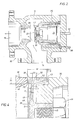
- Figure 1 is a cross section of a pilot operated pressure relief valve with the improved valve member of this invention shown in a closed position;
- Figure 2 is a cross section of the pilot operated pressure relief valve shown in Figure 1 with the valve member shown in an open position to permit fluid flow through the valve for relieving fluid pressure;
- Figure 3 is an enlarged view of the reciprocable valve member of Figures 1 and 2 removed from the valve body;
- Figure 4 is an enlarged fragment of Figure 3 illustrating particularly the sizing of the members forming the shock absorbing sealing means of the present invention and showing in broken lines the final position of the valve member after flexing of the connecting member;
- Figure 5 is a cross section of another embodiment of the present invention showing a non-pilot operated pressure relief valve in closed position;
- Figure 6 is an enlarged fragment of Figure 5 showing the valve member utilized therein; and
- Figure 7 is an enlarged section of the valve member showing a portion thereof in seated position with the connecting member shown in broken lines in flexed position for absorbing impact forces after seating of the sealing means.
- Referring now to the drawings and more particularly to the embodiment shown in Figures 1-4, a pilot operated safety relief valve is shown generally at 10 having a
valve body 12 defining an inlet flow passage at 14 and an outlet flow passage at 16. A nozzle or seat ring is shown generally at 18 and has a generally planar seat face at 20. An improved reciprocable valve member is generally indicated at 22 having adome chamber 24 therein and mounted for movement between open and closed positions. A metering or dampening chamber is shown at 26 (Fig. 2) to reduce the impact ofvalve member 22 againstseat ring 18 when moving to closed position after being opened. A pilot valve for controllingrelief valve 10 is shown schematically at 28 having aninlet line 30 in fluid communication withinlet 14 and adome line 32 extending todome chamber 24. An exhaust ordischarge line 34 extends to atmosphere. - Valve
member 22 includes abody 35 having a disk including central hub shown generally at 36, an outer seal ring shown generally at 38, and a flexible connecting member shown generally at 40 extending between and connectinghub 36 toseal ring 38.Seal ring 38 has aplanar sealing face 42 between radially inner and outer peripheral surfaces thereof adapted to contact and seat onface 20 ofseat ring 18 upon closing ofvalve member 22 after opening thereof. Valvemember 22 moves to an open position as shown in Figure 2 resulting from a predetermined high fluid pressure being reached ininlet passage 14 sensed bypilot line 30. Upon a reduction in fluid pressure ininlet fluid passage 14 as sensed bypilot valve 28,valve member 22 reseats onseat ring 18. Oftentimes, even with dampening of the movement ofvalve member 22, and particularly upon a relative fast reduction in fluid pressure influid inlet passage 14 after opening,valve member 22 moves rapidly to closed seated position to exert impact forces againstseat ring 18. Impact forces may cause abnormal wear or damage which could effect fluid leakage in the closed position ofvalve member 22. - The present invention utilizes a flexible connecting
member 40 betweenhub 36 and the inner radial periphery ofouter seal ring 38 which flexes after initial contact ofseal ring 38 withseat ring 18 for absorbing impact forces. Flexible connectingmember 40 is constructed and arranged for a predetermined flexure relative toseal ring 38 for absorbing impact forces with minimal radial and angular deflection of sealingface 42 onseal ring 38 and for providing alignment betweenfaces - As shown in Figure 4,
central hub 36 ofvalve member 22 moves an axial distance D after contact ofseal face 42 withseat face 20. Distance D is at least greater than around 0.0508mm (0.002 inch) and may be as high as around 0.762mm (0.030 inch) or greater depending primarily on such factors as the size ofvalve member 22 and various operating parameters.Seat ring 38 has a planarrear face 41 andvalve member body 35 has anopposed face 43 normally spaced fromface 41 and acting as a stop upon contact withrear face 41 to limit the maximum travel S ofhub 36 past the elastic limit of connectingmember 40 afterseat face 20 is contacted byseal ring 38. -
Hub 36 is secured tobody 35 ofvalve member 22 by a threaded bolt shown at 44 threaded within an internally threadedopening 45 inhub 36. Longitudinal axis of flexible connectingmember 40 is shown at 46 (Fig. 4). Connectingmember 40 is hinged tohub 36 atpoint 48, and hinged to sealring 38 at 50. The thickness of connectingmember 40 is indicated at T. -
Seal ring 38 has a maximum thickness indicated at T1, and a width indicated at W. The center of gravity ofseal ring 38 is indicated at 52 and is offset an axial distance D1 from the center line of connectingmember 40 athinge point 50 in a direction away from or longitudinally outwardly ofseal face 42. Such an offset has been found desirable in order to minimize any angular or radial deflection ofseal face 42 upon flexing of connectingmember 40 resulting from movement ofhub 36 afterseal face 42contacts seat face 20. An offset distance D1 of at least around 1.27mm (0.050 inch) is believed desirable in order to minimize the deflection of theseal face 42 to an insignificant amount. - Further, in order for the flexing of connecting
member 40 to maintain alignment ofseal face 42 againstseat face 20 upon impacting ofseal ring 38 againstseat ring 18, it is desirable that the maximum thickness T1 ofseal ring 38 be at least around twice the thickness T of connectingmember 40, and that the total width W ofseal ring 35 be at least around three times the thickness T of connectingmember 40. Additionally, in order to minimize the angular and radial deflection offace 42 upon flexure of connectingmember 40, thelongitudinal axis 46 of connectingmember 40 is inclined rearwardly to provide a negative slope shown at angle A. It is believed that angle A should be between around one-half degree and ten degrees in order to obtain a satisfactory result. -
Planar face 42 is of a width greater than the width ofplanar face 20 for the most effective sealing action and with minimal radial and angular deflections occurring after contact. Such an arrangement accommodates any lack of concentricity betweenrings seal face 42 is wider thanseat face 20 sinceseal face 42 is formed of a harder face material. - It is apparent from the above that the design of the flexible connecting
member 40 betweenseal ring 38 andhub 36 may be predetermined in order to have sufficient flexure to absorb the impact forces while minimizing the deflection ofseal face 42. Whilehub 36, connectingmember 40, andseal ring 35 are shown as an integral construction, it is to be understood that connecting member 4'0 may be formed of a separate member, if desired, such as a Belleville washer. - While metals are the preferred materials from which the
seat ring 18 andseal ring 38 are formed, it is to be understood that other hard materials resistant to high temperature, such as certain types of ceramic and composite materials, may be utilized in a satisfactory manner. The term "hard" as used in the specification and claims herein is interpreted as being "non-elastomeric". - Referring now to Figure 5-7, another embodiment of the present invention is illustrated for a pressure relief valve which is not pilot operated. Pressure relief valve 10A has a
valve body 12A including aninlet flow passage 14A and an outlet flow passage 16A. A nozzle orseat ring 18A has aplanar seat face 20A. Aspindle 22A has abore 45A. - Improved pressure relief valve 10A includes
hub 36A fitted withinbore 45A, aseal ring 38A, and a flexible connectingmember 40A. Aspring 57A urgesspindle 22A andseal ring 38A into seated position onface 20A ofseat ring 18A. Upon a predetermined high fluid pressure being reached ininlet fluid passage 14A,spindle 22A andseal ring 38A are forced outwardly against the bias ofspring 57A to permit fluid flow through fluid passage 16A. Upon a reduction in fluid pressure ininlet 14A,spindle 22A under the bias ofspring 57A movesseal ring 38A to reseated position onface 20A ofseat ring 18A. - Flexible connecting member or
web 40A functions in the same manner as the embodiment of Figure 1-4 and is generally identical to the embodiment of Figure 1-4 except for the slope of connectingmember 40A shown at angle A and the location of the center of gravity shown atpoint 52A. Thelongitudinal axis 46A of connectingmember 40A has a positive slope shown at angle A betweenhinge points face 42A instead of away fromface 42A as in the embodiment of Figures 1-4. Additionally, in order to minimize deflection offace 42A after contact againstface 20A, the center ofgravity 52A ofseal member 38A is positioned forwardly ofhinge point 50A towardface 42A as shown at D1. Distance D1 is generally identical to the distance D1 in the embodiment shown in Figures 1-4 except in an opposite direction thereby to minimize the deflection offace 42A resulting from the flexing of connectingmember 40A.Hub 36A moves a distance D as in the embodiment of Figures 1-4 and faces 41A and 43A engage in abutting contact to limit the movement ofhub 36A past the elastic limit of connectingmember 40A. - While the present invention has been illustrated for utilization with pressure relief valves, it is to be understood that this invention could be utilized with other types of valves such as check valves, where a reciprocable valve member is provided for seating and reseating against an annular seat ring.
Claims (27)
- A fluid operated valve (10, 10A) having a valve body (12, 12A) including a flow passage and a hard annular seat ring (18, 18A) mounted within the valve body about the flow passage, and a fluid pressure responsive reciprocable valve member (22, 22A) mounted within the valve body for movement between opened and closed positions relative to said flow passage and adapted to seat in the closed position on said hard seat ring, said valve member including a central hub (36, 36A), an outer annular seal ring (38, 38A) having radially inner and outer peripheral surfaces and a connecting member (40, 40A) extending between said hub and said seal ring, characterized by:
said outer annular seal ring (38, 38A) being a hard seal ring for seating in face-to-face contact relation with said seat ring in the closed position of said valve member, and said radially inner and outer peripheral surfaces on said hard seal ring being spaced radially from said central hub; and
said connecting member (40, 40A) being flexible for flexing between said central hub (36, 36A) and said inner peripheral surface of said seal ring after initial contact of said hard seal ring (38, 38A) with said hard seat ring (18, 18A) to absorb impact loads resulting from contact of said hard seal ring against said hard seat ring without substantial movement of said hard seal ring. - A fluid operated valve as set forth in Claim 1, wherein said seal ring (38, 38A) and said hard seat ring (18, 18A) have generally planar sealing faces (42, 42A, 20, 20A) in contact with each other in the closed position of said valve member.
- A fluid operated valve as set forth in Claim 2, wherein said sealing faces (42, 42A) of said hard seal ring (38, 38A) are of a width greater than the width of said seal face (20, 20A) on said hard seat ring (18, 18A), said sealing faces initially contacting each other along substantially the entire width of said seat ring face (18, 18A) and providing minimal deflection between said contacting faces.
- A fluid operated valve as set forth in any preceding claim, wherein said connecting member (40, 40A) is hinged at opposed ends thereof to said central hub (36, 36A) and to said hard seal ring (38, 38A).
- A fluid operated valve as set forth in any preceding claim, wherein said connecting member (40, 40A) is slanted from said central hub (36, 36A) to said hard seat ring (18, 18A) a predetermined amount in a direction at right angles to a radial direction, thereby to provide increased resistance to radial deflection of said seal ring after initial contact of said seal ring against said hard seat ring.
- A fluid operated valve as set forth in Claim 5, wherein said connecting member (40) is slanted in a direction away from said hard seat ring (18) with the center of gravity (52) of said hard seal ring (38) being positioned axially outwardly of said connecting member relative to said hard seat ring for minimizing radial deflection of the seal ring.
- A fluid operated valve as set forth in Claim 5, wherein said connecting member (40A) is slanted in a direction toward said hard seat ring (18A) with the center of gravity (52A) of said hard seal ring (38A) being positioned axially inwardly of said connecting member relative to said hard seat ring for minimizing radial deflection of the seal ring.
- A fluid operated valve as set forth in Claim 6 or Claim 7 when appendant to Claim 4, wherein said center of gravity (52, 52A) is offset at least 1.27 mm (0.050 inch) in a direction parallel to the longitudinal axis of said connecting member (40, 40A) from a hinge point (50, 50A) of said connecting member to said hard seal ring (38, 38A).
- A fluid operated valve as set forth in any preceding claim, wherein after initial contact of said hard seal ring (38, 38A) with said hard seat ring (18, 18A), said central hub (36, 36A) moves longitudinally relative to said seal ring a distance sufficient to absorb impact loads resulting from contact of said hard seal ring against said hard seat ring.
- A fluid operated valve as set forth in Claim 9, wherein said central hub (36, 36A) moves relative to said seal ring a distance of at least 0.0508 mm (0.002 inch).
- A fluid operated valve as set forth in Claim 10, wherein said distance is from 0.0508 mm (0.002 to 0.030 inch).
- A fluid operated valve as set forth in any preceding claim, wherein said central hub (36, 36A) and said connecting member (40, 40A) are integral.
- A fluid operated valve as set forth in any preceding claim, wherein said seal ring (38, 38A) and said connecting member (40, 40A) are integral.
- A fluid operated valve as set forth in Claim 12 or Claim 13, wherein said central hub (36, 36A), said seal ring (38, 38A) and said flexible connecting member (40, 40A) are a one-piece integral structure.
- A fluid operated valve as set forth in any preceding claim, wherein said seal ring (38, 38A) has a width as measured in a direction parallel to the longitudinal axis (46, 46A) of said connecting member (40, 40A) at least three times the thickness of said connecting member.
- A fluid operated valve as set forth in any preceding claim, wherein said seal ring (38, 38A) has a thickness as measured in a direction transverse to the longitudinal axis (46, 46A) of said connecting member (40, 40A) at least twice the thickness of said connecting member.
- A fluid operated valve as set forth in any preceding claim, wherein said hard seat ring (18, 18A) is a metal seat ring fixed within the valve body (12, 12A).
- A valve member (22, 22A) for mounting within a flow passage of a fluid operated valve for reciprocal movement in response to fluid pressure between opened and closed positions relative to the flow passage and adapted to seat in the closed position on a hard annular seat ring mounted about the flow passage, the valve member including a central hub (36,36A), an outer annular seal ring (38,38A) having radially inner and outer peripheral surfaces and a connecting member (40,40A) extending between said hub and said seal ring, characterized by:
said outer annular seal ring (38,38A) being a hard seal ring for seating in face-to-face contact relation with the seat ring of the valve in the closed position of the valve member and said radially inner and outer peripheral surfaces on said hard seal ring being spaced radially from said central hub; and
said connecting member (40,40A) being flexible for flexing between said central hub (36,36A) and said inner peripheral surface of said seal ring whereby said hard seal ring (38,38A) is adapted to absorb impact loads following initial contact of said hard seal ring against the hard seat ring of the valve without substantial movement of said hard seal ring. - A valve member as set forth in Claim 18, wherein said connecting member (40, 40A) is hinged at opposed ends thereof to said central hub (36, 36A) and to said hard seal ring (38, 38A).
- A valve member as set forth in Claim 18 or Claim 19, wherein said central hub (36, 36A) and said connecting member (40, 40A) are integral.
- A valve member as set forth in any one of Claims 18-20, wherein said seal ring (38, 38A) and said connecting member (40, 40A) are integral.
- A valve member as set forth in Claim 20 or Claim 21, wherein said central hub (36, 36A), said seal ring (38, 38A) and said flexible connecting member (40, 40A) are a one-piece integral structure.
- A valve member as set forth in any one of Claims 18-22, wherein said seal ring (38, 38A) has a width as measured in a direction parallel to the longitudinal axis (46, 46A) of said connecting member (40, 40A) at least three times the thickness of said connecting member.
- A valve member as set forth in any one of Claims 18-23, wherein said seal ring (38, 38A) has a thickness as measured in a direction transverse to the longitudinal axis (46, 46A) of said connecting member (40, 40A) at least twice the thickness of said connecting member.
- A valve member as set forth in any one of Claims 18-23, wherein said seal ring (38, 38A) has generally planar sealing faces (42, 42A) for contacting correspondingly planar sealing faces on the seat ring of the valve member.
- A valve member as set forth in any one of Claims 18-25, wherein said connecting member (40, 40A) in its unflexed position is slanted from said central hub (36, 36A) to said hard seal ring (38, 38A) a predetermined amount in a direction at right angles to a radial direction, thereby to provide increased resistance to radial deflection of said seal ring on contact with the seat ring of the valve member.
- A valve member as set forth in Claim 19, or in any one of Claims 20-26 when appendant to Claim 19, wherein the center of gravity (52, 52A) of said hard seal ring (38, 38A) is offset at least 1.27 mm (0.050 inch) in a direction parallel to the longitudinal direction of said connecting member (40, 40A) from a hinge point (50, 50A) of said connecting member to said hard seal ring (38, 38A).
Applications Claiming Priority (2)
| Application Number | Priority Date | Filing Date | Title |
|---|---|---|---|
| US07/502,047 US5011116A (en) | 1990-03-30 | 1990-03-30 | Shock absorbing sealing means for flow control devices |
| US502047 | 1990-03-30 |
Publications (2)
| Publication Number | Publication Date |
|---|---|
| EP0449668A1 EP0449668A1 (en) | 1991-10-02 |
| EP0449668B1 true EP0449668B1 (en) | 1994-11-30 |
Family
ID=23996109
Family Applications (1)
| Application Number | Title | Priority Date | Filing Date |
|---|---|---|---|
| EP91302869A Expired - Lifetime EP0449668B1 (en) | 1990-03-30 | 1991-04-02 | Shock absorbing sealing means for flow control devices |
Country Status (7)
| Country | Link |
|---|---|
| US (1) | US5011116A (en) |
| EP (1) | EP0449668B1 (en) |
| JP (1) | JP3080680B2 (en) |
| KR (1) | KR100202514B1 (en) |
| CA (1) | CA2039071C (en) |
| DE (1) | DE69105324T2 (en) |
| MX (1) | MX173878B (en) |
Families Citing this family (19)
| Publication number | Priority date | Publication date | Assignee | Title |
|---|---|---|---|---|
| US5370151A (en) * | 1994-03-23 | 1994-12-06 | Dresser Industries Inc. | Safety valve |
| US5590684A (en) * | 1995-09-01 | 1997-01-07 | Keystone International Holdings Corporation | Dual pilot manifold assembly for a safety relief valve |
| US5937896A (en) * | 1998-08-07 | 1999-08-17 | Mitsubishi Denki Kabushiki Kaisha | Check valve and seating valve |
| US6705339B2 (en) | 2002-05-28 | 2004-03-16 | Ga Industries, Inc. | Surge check unit for a liquid distribution system |
| US8397763B2 (en) * | 2009-10-23 | 2013-03-19 | Bend Tech, LLC | Low pressure valve assembly |
| DE102011005485A1 (en) * | 2011-03-14 | 2012-09-20 | Robert Bosch Gmbh | Valve device for switching or metering a fluid |
| US10436341B1 (en) * | 2017-10-20 | 2019-10-08 | KHOLLE Magnolia 2015, LLC | Pressure relief valves |
| JPWO2022030309A1 (en) | 2020-08-03 | 2022-02-10 | ||
| EP4194726B1 (en) | 2020-08-04 | 2025-11-19 | Eagle Industry Co., Ltd. | Valve |
| KR102891391B1 (en) | 2020-08-04 | 2025-11-27 | 이구루코교 가부시기가이샤 | valve |
| JP7631350B2 (en) | 2020-08-04 | 2025-02-18 | イーグル工業株式会社 | Expansion valve |
| JP7673070B2 (en) | 2020-08-04 | 2025-05-08 | イーグル工業株式会社 | valve |
| KR102879499B1 (en) | 2020-09-28 | 2025-10-31 | 이구루코교 가부시기가이샤 | valve |
| EP4224032B1 (en) * | 2020-10-01 | 2025-12-10 | Eagle Industry Co., Ltd. | Valve |
| EP4265949B1 (en) | 2020-12-17 | 2025-11-19 | Eagle Industry Co., Ltd. | Valve |
| US20220196181A1 (en) * | 2020-12-23 | 2022-06-23 | Goodrich Corporation | Inflatable systems with electro-pneumatic valve modules |
| US12510168B2 (en) | 2021-03-29 | 2025-12-30 | Eagle Industry Co., Ltd. | Valve |
| US11598436B2 (en) * | 2021-04-14 | 2023-03-07 | Dresser, Llc | Safety valves for use at extremely high temperatures |
| US20250277534A1 (en) * | 2024-03-04 | 2025-09-04 | Curtiss-Wright Flow Control Corporation | Low pressure relief valve |
Family Cites Families (22)
| Publication number | Priority date | Publication date | Assignee | Title |
|---|---|---|---|---|
| US813555A (en) * | 1905-04-13 | 1906-02-27 | Crane Co | Spring-disk valve. |
| US820154A (en) * | 1905-07-12 | 1906-05-08 | Nathan P Towne | Valve. |
| US1781771A (en) * | 1926-01-25 | 1930-11-18 | Wilson Rings Company | Valve |
| US1800127A (en) * | 1926-01-25 | 1931-04-07 | Wilson Rings Company | Valve |
| US1654516A (en) * | 1926-01-25 | 1927-12-27 | Wylie G Wilson | Valve |
| US1671140A (en) * | 1926-01-25 | 1928-05-29 | Wylie G Wilson | Valve |
| US1679779A (en) * | 1926-04-08 | 1928-08-07 | William F Oberhuber | Valve and flanged seal |
| US1878222A (en) * | 1927-10-04 | 1932-09-20 | Wylie G Wilson | Valve and the like |
| US1847385A (en) * | 1930-05-26 | 1932-03-01 | Dengler Benjamin Franklin | Valve |
| US2163472A (en) * | 1936-07-07 | 1939-06-20 | Oil Well Supply Co | Valve |
| US2628632A (en) * | 1946-04-09 | 1953-02-17 | Manning Maxwell & Moore Inc | Safety valve |
| US2643671A (en) * | 1952-06-21 | 1953-06-30 | Manning Maxwell & Moore Inc | Spring loaded pop-safety valve |
| US3063467A (en) * | 1960-04-08 | 1962-11-13 | Mission Mfg Co | Valve seats |
| US3141474A (en) * | 1962-08-15 | 1964-07-21 | Perry H Gentzel | Safety valve construction |
| US3211174A (en) * | 1963-04-17 | 1965-10-12 | Anderson Greenwood & Co | Pressure relief or blowdown valve |
| US3430646A (en) * | 1966-11-21 | 1969-03-04 | Bendix Corp | Hot gas relief valve |
| GB1164678A (en) * | 1966-12-27 | 1969-09-17 | Toa Valve Company Ltd | Improvements relating to Pop Safety Valves |
| US3702141A (en) * | 1971-02-22 | 1972-11-07 | Dresser Ind | Gas type safety valve |
| US4188013A (en) * | 1977-08-08 | 1980-02-12 | Honeywell Inc. | Gas valve seating member |
| JPS5551173A (en) * | 1978-10-09 | 1980-04-14 | Toa Valve Kk | Preparation of valve body in safety valve |
| DE3532796A1 (en) * | 1985-09-19 | 1987-03-26 | Voroshilovgrad Mashinostr | Knife gate valve |
| US4858642A (en) * | 1988-01-25 | 1989-08-22 | Dresser Industries, Inc. | Impact resistant pressure relief valve |
-
1990
- 1990-03-30 US US07/502,047 patent/US5011116A/en not_active Expired - Lifetime
-
1991
- 1991-03-26 CA CA002039071A patent/CA2039071C/en not_active Expired - Lifetime
- 1991-03-29 JP JP03091556A patent/JP3080680B2/en not_active Expired - Lifetime
- 1991-03-30 KR KR1019910005075A patent/KR100202514B1/en not_active Expired - Fee Related
- 1991-04-01 MX MX025160A patent/MX173878B/en unknown
- 1991-04-02 EP EP91302869A patent/EP0449668B1/en not_active Expired - Lifetime
- 1991-04-02 DE DE69105324T patent/DE69105324T2/en not_active Expired - Lifetime
Also Published As
| Publication number | Publication date |
|---|---|
| EP0449668A1 (en) | 1991-10-02 |
| KR910017107A (en) | 1991-11-05 |
| DE69105324T2 (en) | 1995-05-18 |
| CA2039071C (en) | 2001-08-14 |
| JPH04219581A (en) | 1992-08-10 |
| JP3080680B2 (en) | 2000-08-28 |
| CA2039071A1 (en) | 1991-10-01 |
| DE69105324D1 (en) | 1995-01-12 |
| US5011116A (en) | 1991-04-30 |
| KR100202514B1 (en) | 1999-06-15 |
| MX173878B (en) | 1994-04-07 |
Similar Documents
| Publication | Publication Date | Title |
|---|---|---|
| US5011116A (en) | Shock absorbing sealing means for flow control devices | |
| EP0326509B1 (en) | Impact resistant pressure relief valve | |
| EP0084924B1 (en) | Valve seats | |
| US4944489A (en) | Rotary valve and seal | |
| US4867286A (en) | Shock absorber having fluid amplified piston head with relief valve which provides second stage of fluid amplification | |
| CA1291104C (en) | High strength ball valve seat assembly | |
| CA1068922A (en) | Pivot joint | |
| US5064169A (en) | Shock absorbing means for flow control devices | |
| US5170989A (en) | Sealing assembly for valve member | |
| US3903923A (en) | Stabilized relief valve | |
| GB2046407A (en) | Pressure-relief valve device | |
| EP3244108B1 (en) | Check valves | |
| CA1133877A (en) | Ball valve and seat assembly | |
| CN210565971U (en) | Differential type safety valve assembly for hydraulic damper | |
| US4712769A (en) | High temperature balanced valve trim | |
| US5868160A (en) | Two-way insert valve | |
| EP0870137B1 (en) | Valve | |
| US4522230A (en) | Orifice plate seal ring for controlled closure check valve | |
| GB2036930A (en) | Rotary valve | |
| WO2002066875A1 (en) | Valve with fluid pressure reduction device with integral guides | |
| CA1187378A (en) | Reseat relief valve | |
| EP3792504B1 (en) | Hydraulic actuator end stroke stop pressure/load control | |
| CA1250274A (en) | Valve casing for use in a butterfly valve | |
| CA2177315C (en) | Quick coupling for fluids under pressure | |
| JPH07260016A (en) | Eccentrically rotating-type flow adjusting valve |
Legal Events
| Date | Code | Title | Description |
|---|---|---|---|
| PUAI | Public reference made under article 153(3) epc to a published international application that has entered the european phase |
Free format text: ORIGINAL CODE: 0009012 |
|
| AK | Designated contracting states |
Kind code of ref document: A1 Designated state(s): DE FR GB IT |
|
| 17P | Request for examination filed |
Effective date: 19911115 |
|
| 17Q | First examination report despatched |
Effective date: 19930517 |
|
| GRAA | (expected) grant |
Free format text: ORIGINAL CODE: 0009210 |
|
| AK | Designated contracting states |
Kind code of ref document: B1 Designated state(s): DE FR GB IT |
|
| PG25 | Lapsed in a contracting state [announced via postgrant information from national office to epo] |
Ref country code: IT Free format text: LAPSE BECAUSE OF FAILURE TO SUBMIT A TRANSLATION OF THE DESCRIPTION OR TO PAY THE FEE WITHIN THE PRESCRIBED TIME-LIMIT;WARNING: LAPSES OF ITALIAN PATENTS WITH EFFECTIVE DATE BEFORE 2007 MAY HAVE OCCURRED AT ANY TIME BEFORE 2007. THE CORRECT EFFECTIVE DATE MAY BE DIFFERENT FROM THE ONE RECORDED. Effective date: 19941130 |
|
| REF | Corresponds to: |
Ref document number: 69105324 Country of ref document: DE Date of ref document: 19950112 |
|
| ET | Fr: translation filed | ||
| PLBE | No opposition filed within time limit |
Free format text: ORIGINAL CODE: 0009261 |
|
| STAA | Information on the status of an ep patent application or granted ep patent |
Free format text: STATUS: NO OPPOSITION FILED WITHIN TIME LIMIT |
|
| 26N | No opposition filed | ||
| REG | Reference to a national code |
Ref country code: GB Ref legal event code: IF02 |
|
| REG | Reference to a national code |
Ref country code: GB Ref legal event code: 732E |
|
| REG | Reference to a national code |
Ref country code: FR Ref legal event code: CA Ref country code: FR Ref legal event code: TP Ref country code: FR Ref legal event code: CD |
|
| PGFP | Annual fee paid to national office [announced via postgrant information from national office to epo] |
Ref country code: FR Payment date: 20100506 Year of fee payment: 20 |
|
| PGFP | Annual fee paid to national office [announced via postgrant information from national office to epo] |
Ref country code: DE Payment date: 20100428 Year of fee payment: 20 |
|
| PGFP | Annual fee paid to national office [announced via postgrant information from national office to epo] |
Ref country code: GB Payment date: 20100426 Year of fee payment: 20 |
|
| REG | Reference to a national code |
Ref country code: DE Ref legal event code: R071 Ref document number: 69105324 Country of ref document: DE |
|
| REG | Reference to a national code |
Ref country code: GB Ref legal event code: PE20 Expiry date: 20110401 |
|
| PG25 | Lapsed in a contracting state [announced via postgrant information from national office to epo] |
Ref country code: GB Free format text: LAPSE BECAUSE OF EXPIRATION OF PROTECTION Effective date: 20110401 |
|
| PG25 | Lapsed in a contracting state [announced via postgrant information from national office to epo] |
Ref country code: DE Free format text: LAPSE BECAUSE OF EXPIRATION OF PROTECTION Effective date: 20110402 |