EP0449507A1 - A low pressure gas discharge lamp - Google Patents
A low pressure gas discharge lamp Download PDFInfo
- Publication number
- EP0449507A1 EP0449507A1 EP91302474A EP91302474A EP0449507A1 EP 0449507 A1 EP0449507 A1 EP 0449507A1 EP 91302474 A EP91302474 A EP 91302474A EP 91302474 A EP91302474 A EP 91302474A EP 0449507 A1 EP0449507 A1 EP 0449507A1
- Authority
- EP
- European Patent Office
- Prior art keywords
- tube
- end portion
- low pressure
- pressure gas
- discharge lamp
- Prior art date
- Legal status (The legal status is an assumption and is not a legal conclusion. Google has not performed a legal analysis and makes no representation as to the accuracy of the status listed.)
- Withdrawn
Links
Images

Classifications
-
- H—ELECTRICITY
- H01—ELECTRIC ELEMENTS
- H01J—ELECTRIC DISCHARGE TUBES OR DISCHARGE LAMPS
- H01J65/00—Lamps without any electrode inside the vessel; Lamps with at least one main electrode outside the vessel
Definitions
- the present invention relates to a low pressure gas discharge lamp having an inner electrode disposed in a tube and an outer electrode disposed on a surface of the tube.
- a gas discharge lamp as described above has an inner electrode provided at one end of a rod shaped glass tube forming a slender discharge space and a belt shaped outer electrode provided along the axial direction of the tube on the outer surface of the tube.
- the lamp has a phosphor layer emitting visible light coated on the inner surface of the tube.
- the phosphor is excited by U.V. radiation emitted from the filling gas such as mercury vapor or xenon, which emits the radiation due to a discharge generated between the inner electrode and the outer electrode.
- a lamp having a gas such as neon, which emits visible light is described in the above publications.
- the present invention seeks to provide a low pressure gas discharge lamp having improved and desirable distribution of its brightness.
- a low pressure gas discharge lamp comprises: an elongated hollow tube having inner and outer surfaces; a filling gas contained in said tube for emitting radiation in response to a discharge; an inner electrode disposed in a first end portion of said tube; and an outer electrode having a belt shape portion formed on the outer surface of said tube along an axial direction of said tube between said first end portion and a second end portion of said tube and a ring shape portion, connected to said belt shape portion, formed on said outer surface of said tube around said second end portion of said tube, whereby said discharge is generated between said inner electrode and said outer electrode.
- the present invention will now be described with respect to a first embodiment in which the present invention is applied to a low pressure gas discharge lamp used as a display needle of an instrument.
- a low pressure gas discharge lamp 21 used as a display needle comprises a hollow rod shape glass tube 23 formed with a slender discharge space 25 (shown in Fig. 4) therein.
- the glass tube 23 has, for example, an outer diameter of 2.5 mm, an inner diameter of 1.5 mm, a thickness of 0.5 mm, a total length of approx. 60 mm, and is formed in a needle shape.
- An inner electrode 27 is attached airtightly at first end portion 29 of the tube 23.
- the electrode 27 is a cold cathode type made from a nickel tube having a hollow including electron emitting material (not shown) therein and is connected to a lead wire 31 hermetically passed through a pinch seal portion 33 of the first end portion 29.
- the lead wire 31 is made of a dumet wire having a diameter of 0.3 mm.
- the second end portion (the top end portion) 35 of the tube 23 does not have an inner electrode.
- the glass tube at the top end portion 35 is shaped as a lump (thick portion) 352 having a thickness L1 which is thicker than that at the other portions of the tube 23, which has a wall thickness of 0.5 mm, as shown in Fig. 3 and Fig. 4.
- the glass tube at the top end portion 35 swells (extends) to both directions i.e., outside and inside of the tube 23, along the axis of the tube 23 and forms a lump (thick portion) 352. Accordingly, the wall thickness of the lump (thick portion) 352 of the top end portion 35 is much more than that of other portions of the tube 23.
- the top end portion 35 Since the lump (thick portion) 352 of the top end portion 35 is thicker than the other portions of the tube 23, the top end portion 35 is tough against a shock caused by something hitting it.
- the lamp 21 is exhausted from and sealed at the top end portion 35 without any special exhaust tube. Therefore the lamp 21 and the discharge space 25 have almost even thickness from the first end portion 29 to the top end portion 35 and the thickness of the positive column of the discharge is even from the first end portion 29 to the top end portion 35. As the result, the lamp 21 does not have the fault that the brightness of the lamp 21 near the top end portion 35 is lower than that at the other portions of the lamp 21, which is caused by the positive column of the discharge becoming thinner near the top end portion 35.
- a phosphor layer 37 is coated on an inner surface of the tube 23 and is extending beyond the inner top 354 of the lump 352 at the top end portion 35. Because of this, near the top end portion 35 sufficient light is emitted.
- the phosphor layer 37 is coated before attaching of the inner electrode 27, exhausting of the tube 23 and of sealing the top end portion 35.
- Xenon gas is sealed between 5-40 Torr, or preferably approx. 20-40 Torr, in the tube 23.
- An outer electrode 39 having a belt shape portion 392, a ring shape portion 394 and a cap shape portion 396 is provided along the axial direction of the tube 23 on the outer surface of the tube 23, as is indicated by the hatching area in Fig. 3.
- the outer electrode 39 is made by coating, in a belt shape, a ring shape and a cap shape, the predetermined portion of the tube 23 with paste such as carbon phenol or silver epoxy, baking it, and forming it in a film shape.
- the outer electrode 39 is formed from the area opposite to the inner electrode 27 to the top end portion 35 of the tube 23.
- the belt shape portion 392 of the outer electrode 39 has a width covering the center angle A1 of more than 120 degree , as shown in Fig. 5, along almost all length of the tube except for the top end portion 35 of the tube 23 and an area nearby.
- the cap shape portion 396 and the ring shape portion 394 of the outer electrode 39 cover the top end portion 35 of the tube 23 and the area nearby, respectively.
- Both portions 394, 396 have the length L2 altogether and are extending beyond the inner top 354 of the lump (thick portion) 352 from the top of the top end portion 35, as shown in Fig. 4.
- the length L2 is longer than the length L1 of the lump (thick portion) 352.
- the ring shape portion 394 of the outer electrode 39 covers the outer surface of the tube 23 in an area corresponding to the inner surface of the lump (thick portion) 352 in a ring shape.
- the inner surface of the lump (thick portion) 352 defines a boundary between a top portion of the discharge space 25 and the tube 23 at the top end portion 35.
- the cap shape portion 396 of the outer electrode 39 covering the top end portion 35 of the tube 23 is not always necessary.
- a first receptacle terminal 41 is formed on the outer surface of the first end portion 29 of the tube 23 and is connected electrically to the lead wire 31. Accordingly the first receptacle terminal 41 is connected electrically to the inner electrode 27 through the lead wire 31.
- the first receptacle terminal 41 is made by coating in a cap shape with paste such as carbon phenol or silver epoxy and baking it.
- a second receptacle terminal 43 is provided at a position isolated axially with respect to the first receptacle terminal 41 on the outer surface of the tube 23 and is connected to the outer electrode 39.
- the second receptacle terminal 43 is made by coating in a semicircular shape with paste such as carbon phenol or silver epoxy and baking it around the tube 23. Further, the second receptacle terminal 43 surrounds the tube 23 except for a light transmitting slit portion 45 of a shielding film 47 to be described later.
- the shielding film 47 formed on the outer surface of the tube 23 is composed of carbon, epoxy resin and adhensive.
- the shielding film 47 is formed to cover the outer electrode 39 on the surface of the tube 23, and the light transmitting slit portion 45 not covered by the shielding film 47 extends along the axial direction on the surface opposed to the surface formed with the belt shape portion 392 of the outer electrode 39.
- the outer electrode 39 is formed, as shown in the sectional view of Fig. 5, on a partial outer surface of tube 23, and the light transmitting slit portion 45 is not covered by the shielding film 47 and is formed on the tube 23 opposite (by 180 degrees) to the belt shape portion 392 of the outer electrode 39. Accordingly, the light in the tube 23 is externally radiated only through the light transmitting slit portion 45. Thus the lamp 21 works as an aperture type.
- the the angle A1 of the belt shape portion 392 of the outer electrode 39 is wider than angle A2 of the light transmitting slit portion 45.
- the shielding film 47 covers the entire surface of the tube 23 except for the first and second receptacle terminals 41 and 43 and the light transmitting slit portion 45, and the first and second receptacle terminals 41 and 43 are exposed directly to the outside of the lamp 21.
- Fig. 6 shows that the shielding film 47 does not cover the second receptacle terminals 43 having the angle A3.
- the shielding film 47 covers the area, having the length L3, of the outer surface of the lamp 21 around the top end portion 35 of the tube 23.
- the length L3 is longer than the total length L2 of the ring shape portion 394 and the cap shape portion 396 of the outer electrode 39.
- the shielding film 47 covers perfectly the ring shape portion 394 and the cap shape portion 396 of the outer electrode 39 and also covers the lump (thick portion) 352.
- the xenon discharge lamp 21 above described is attached to a lamp holder 51 shown in Fig. 1.
- the lamp holder 51 has a U shape of its section and is made of an electrically insulating material.
- First and second terminal pieces 53, 55 for supplying power to the lamp 21 are fixed in the lamp holder 51 so as to be isolated from each other.
- These terminal pieces 53, 55 are formed by bending conductive leaf springs made of phosphorus bronze, etc. in a U shape, to hold the lamp 21 by means of holding sections 552, 554 opposed to each other as shown in Fig. 6.
- the lamp holder 51 is fixed to the rotational shaft 57 to be rotated for display of an instrument.
- the rotational shaft 57 is rotated, the lamp holder 51 is correspondingly pivoted.
- the rotational shaft 57 of this embodiment is composed of a hollow shaft, not shown.
- Two cords (not shown) are inserted into the hollow shaft 57.
- the ends of the inserted cords are respectively connected to the first and second terminal pieces 53, 55 and connected at their other ends to a high frequency power source.
- the lamp 21 is attached at the end portion thereof to the lamp holder 51 so as to connect the inner electrode 27 and the outer electrode 39 with the power source through the first and second receptacle terminals 41 and 43 and the first and second terminal pieces 53 and 55.
- the first and second receptacle terminals 41 and 43 are formed on the outer surface of the tube 23 at positions corresponding respectively to the first and second terminal pieces 53, 55.
- a discharge is generated between the inner and outer electrodes 27 and 39 of the tube 23 by supplying high frequency power to the inner and outer electrodes 27 and 39 through the first and second receptacle terminals 41 and 43.
- This discharge excites xenon gas sealed in the discharge space 25 to irradiate an ultraviolet ray having a spectrum peculiar to the xenon gas.
- This short wavelength ray excites the phosphor film 37, emitting visible light from the phosphor film 37.
- the visible light generated from the phosphor film 37 is radiated externally from the slit portion 45.
- the slit portion 45 is formed in a slender strip shape, in addition to the fact that the tube 23 is originally slender, the lamp 21 is adapted to indicate the display scale as a display needle.
- the lamp holder 51 Since the lamp holder 51 is fixed to the rotational shaft 57 and the lamp holder 51 is, when the rotational shaft 57 is rotated, correspondingly pivoted, the lamp 21 attached to the lamp holder 51 is correspondingly moved to indicate the display scale.
- the ring shape portion 394 of the outer electrode 39 covers the outer surface of the tube 23 corresponding to the inner surface of the lump (thick portion) 352 in a ring shape. Because of this, the positive column of the discharge of the lamp 21 is kept at the central axis of the tube 23 near the top end portion 35 and is prevented from shifting to the direction of the outer electrode 39 near the top end portion 35 of the tube 23. Since the current density in the lamp 21 near the top end portion is smaller than in the other portion of the tube 23, the positive column generated between the inner electrode 27 and the outer electrode 39 is likely to shift from the center of the tube 23 to the direction of the outer electrode 39 near the top end portion. However the outer electrode 39 near the top end portion is formed in the ring shape.
- the positive column of the discharge of the lamp 21 is kept at the centeral axis of the tube 23 near the top end portion 35. Accordingly, the decreasing of the brightness of the lamp 21 near the top end portion 35 is eliminated and sufficient light is emitted near the top end portion 35 of the lamp 21.
- Fig. 7 indicates brightness distribution charactristic diagrams of four lamps.
- line (a) indicates the brightness distribution charactristic diagram of the lamp of the first embodiment above described.
- the line (a) and the lamp (a) correspond to each other.
- the feature of the outer electrode of the lamp (a) is shown in Fig. 7.
- the line (b), the line (c) and the line (d) indicate the brightness distribution charactristics diagrams of the lamp (b), the lamp (c) and the lamp (d) respectively.
- the feature of the outer electrode of each lamp is shown in Fig. 7.
- the lamp (b) and the lamp (c) are experimented models made during the developement of the invention and are compared with lamp (a) of the first embodiment.
- the outer electrode of the lamp (b) has same width along the axis of the lamp and does not have a ring shape portion at the top end portion.
- the outer electrode of the lamp (c) has a belt shape portion along the axis of the lamp and a ring shape portion and a cap shape portion at the top end portion of the lamp.
- the total length L4 of the ring shape portion and the cap shape portion of the outer electrode is shorter than the length L1 of the lump (thick portion) at the top end portion of the lamp.
- Fig. 7 shows that the line (a) corresponding to the brightness of the lamp (a) is more even than either the line (b) or the line (c) corresponding to the brightness of the lamp (b) or the lamp (c) respectively.
- the brightness of the lamp (a) at the top end portion is much more than that of either the lamp (b) or the lamp (c). Since the positive column of the discharge of the lamp (b) shifts to the direction of the outer electrode near the top end portion of the tube, it is observed that the brightness of the lamp (b) at the top end portion decreases.
- a difference in the brightness distribution between the lamp (a) and the lamp (c) is caused by the difference of positions of the ring shape portion and the cap shape portion of the outer electrode.
- the ring shape portion 394 of the outer electrode 39 of the lamp (a) covers the top end portion 35 in an area corresponding to the inside of the thick portion 352 of the tube 23.
- the ring shape portion 394 of the outer electrode 39 of the lamp (a) covers the top end portion 35 in an area corresponding to the boundary between the discharge space 25 and the inner surface, including the inner top 354 of the lump (thick portion) 352, of the top end portion 35 of the tube 23.
- the outer electrode of the lamp (c) does not cover the top end portion 35 in an area corresponding to the boundary between the discharge space 25 and the inner surface of the top end portion 35 of the tube 23.
- the brightness distribution of the lamp (c) is more even near the top end portion than that of the lamp (b) and the brightness of the lamp (c) is much more than that of the lamp (b), as shown in Fig. 7. Because, the lamp (c) has the ring shape portion of the outer electrode, but the lamp (b) does not have the ring shape portion of the outer electrode.
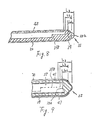
- a second embodiment of the present invention which has the outer electrode including a belt shape portion with a wide portion 398 continuously connected to a ring shape portion, and which is the lamp (d) of Fig. 7, will be described with reference to Fig. 8 and Fig. 9, wherein the same reference numerals as those in the first embodiment denote the same or equivalent components to those in the first embodiment.
- the wide portion 398 of the belt shape portion 392 of the outer electrode 39 is wider than other portions of the belt shape portion 392 of the outer electrode 39.
- the outer electrode 39 has the ring shape portion 394 same as the first embodiment, but does not have the cap shape portion.
- the lamp of this second embodiment has the brightness distribution charactristic diagram indicated by the line (d) in Fig. 7.
- the feature of the outer electrode 39 of the lamp of this second embodiment is described in the lamp (d) in Fig.7.
- the brightness distribution of the lamp 21 of this second embodiment along the axis of the lamp 21 is more even than that of the first embodiment.
- the current density is likely to decrease near the top end portion 35 of the lamp 21.
- the lamp 21 has the outer electrode 39 including the belt shape portion 392 with a wide portion 398.
- the wide portion 398 of the belt shape portion 392 of the outer electrode 39 increases the current density within the discharge space corresponding to the wide portion 398 of the belt shape portion 392 of the outer electrode 39.
- the brightness near the top end portion 35 of the lamp 21 increases and the brightness distribution of the lamp 21 of this second embodiment along the axis of the lamp 21 becomes more even.
- the gas discharge lamp of the present invention is not limited to use as a display needle of an instrument.
- the gas discharge lamp of the present invention may be used for backlighting for a liquid crystal display device, and for image reading in a copying machine, etc.
- the inner electrode is not limited to the cold cathode type, but may be a hot cathode type.
- the outer electrode is not limited to be formed of paste such as carbon phenol or silver epoxy.
- a electroconductive layer as the outer electrode may be formed by vaccum evaporation, or the outer electrode may be formed of a thin metal plate attatched to the surface of the lamp.
- the discharge gas of the gas discharge lamp of the present invention is not limited to xenon, but may be krypton, neon, argon, etc, or mercury as the discharge gas may be sealed in the tube of the gas discharge lamp.
- a phosphor layer is not necessary, since both argon and neon emit visible light by discharge.
Abstract
A low pressure gas discharge lamp (21) comprises an elongated tube (23) filled with a discharge gas. An inner electrode (27) is disposed in a first end portion (29) of the tube (23) and an outer electrode (39) is formed on an outer surface of the tube (23). The outer electrode (39) has a belt shape portion (392) formed on the outer surface of the tube (23) along an axial direction of the tube (23) between the first end portion (29) and a second end portion (35) of the tube (23) and a ring shape portion (394) formed on the outer surface of the tube (23) around the second end portion (35) of the tube (23). The ring shape portion (394) is connected to the belt shape portion (392). The discharge is generated between the inner electrode (27) and the outer electrode (39). The ring shape portion (394) of the outer electrode (39) prevents the discharge from shifting from a central axis of the tube (23) and make the lamp (21) have an even brightness distribution along the axis of the tube (23).
Description
- The present invention relates to a low pressure gas discharge lamp having an inner electrode disposed in a tube and an outer electrode disposed on a surface of the tube.
- In recent years, small gas discharge lamps have been used as parts of display devices.
- More specifically, a light emitting tube composed of an extremely thin hollow glass tube is described in U.S.Patent No. 4,645,979 and U.S.Patent No. 4,871,941. A gas discharge lamp as described above has an inner electrode provided at one end of a rod shaped glass tube forming a slender discharge space and a belt shaped outer electrode provided along the axial direction of the tube on the outer surface of the tube. The lamp has a phosphor layer emitting visible light coated on the inner surface of the tube. The phosphor is excited by U.V. radiation emitted from the filling gas such as mercury vapor or xenon, which emits the radiation due to a discharge generated between the inner electrode and the outer electrode. A lamp having a gas such as neon, which emits visible light, is described in the above publications.
- However this lamp has an undesirable distribution of its brightness because the top portion of the tube, where the inner electrode is not provided, is darker than other portions of the tube. The distribution of its brightness is improved by the art described in U.S.Patent No. 4,887,002, but the brightness of the top portion of the tube is still lower than that of other portions of the tube.
- Accordingly, the present invention seeks to provide a low pressure gas discharge lamp having improved and desirable distribution of its brightness.
- According to the present invention a low pressure gas discharge lamp comprises:
an elongated hollow tube having inner and outer surfaces;
a filling gas contained in said tube for emitting radiation in response to a discharge;
an inner electrode disposed in a first end portion of said tube; and
an outer electrode having a belt shape portion formed on the outer surface of said tube along an axial direction of said tube between said first end portion and a second end portion of said tube and a ring shape portion, connected to said belt shape portion, formed on said outer surface of said tube around said second end portion of said tube, whereby said discharge is generated between said inner electrode and said outer electrode. - In the accompanying drawings:
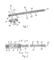
- Fig. 1 is a perspective view of a low pressure gas discharge lamp and a lamp holder according to a first embodiment of the present invention;
- Fig. 2 is a plan view of Fig. 1;
- Fig. 3 is a partial side view of Fig. 1 without a shielding film;
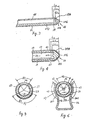
- Fig. 4 is a partial sectional view taken along the line IV-IV of Fig. 2;
- Fig. 5 is a sectional view taken along the line V-V of Fig. 2;
- Fig. 6 is a sectional view taken along the line VI-VI of Fig. 2;
- Fig. 7 illustrates the brightness distribution charactristic diagram of the lamps of the invention;
- Fig. 8 is a partial side view of a low pressure gas discharge lamp without a shielding film according to a second embodiment of the present invention;and
- Fig. 9 is a partial sectional view of Fig. 8.
- The present invention will now be described with respect to a first embodiment in which the present invention is applied to a low pressure gas discharge lamp used as a display needle of an instrument.
- In Fig. 1, a low pressure
gas discharge lamp 21 used as a display needle comprises a hollow rodshape glass tube 23 formed with a slender discharge space 25 (shown in Fig. 4) therein. Theglass tube 23 has, for example, an outer diameter of 2.5 mm, an inner diameter of 1.5 mm, a thickness of 0.5 mm, a total length of approx. 60 mm, and is formed in a needle shape. - An
inner electrode 27 is attached airtightly atfirst end portion 29 of thetube 23. Theelectrode 27 is a cold cathode type made from a nickel tube having a hollow including electron emitting material (not shown) therein and is connected to a lead wire 31 hermetically passed through apinch seal portion 33 of thefirst end portion 29. The lead wire 31 is made of a dumet wire having a diameter of 0.3 mm. - The second end portion (the top end portion) 35 of the
tube 23 does not have an inner electrode. The glass tube at thetop end portion 35 is shaped as a lump (thick portion) 352 having a thickness L1 which is thicker than that at the other portions of thetube 23, which has a wall thickness of 0.5 mm, as shown in Fig. 3 and Fig. 4. The glass tube at thetop end portion 35 swells (extends) to both directions i.e., outside and inside of thetube 23, along the axis of thetube 23 and forms a lump (thick portion) 352. Accordingly, the wall thickness of the lump (thick portion) 352 of thetop end portion 35 is much more than that of other portions of thetube 23. - Since the lump (thick portion) 352 of the
top end portion 35 is thicker than the other portions of thetube 23, thetop end portion 35 is tough against a shock caused by something hitting it. - The
lamp 21 is exhausted from and sealed at thetop end portion 35 without any special exhaust tube. Therefore thelamp 21 and thedischarge space 25 have almost even thickness from thefirst end portion 29 to thetop end portion 35 and the thickness of the positive column of the discharge is even from thefirst end portion 29 to thetop end portion 35. As the result, thelamp 21 does not have the fault that the brightness of thelamp 21 near thetop end portion 35 is lower than that at the other portions of thelamp 21, which is caused by the positive column of the discharge becoming thinner near thetop end portion 35. - A
phosphor layer 37 is coated on an inner surface of thetube 23 and is extending beyond theinner top 354 of thelump 352 at thetop end portion 35. Because of this, near thetop end portion 35 sufficient light is emitted. Thephosphor layer 37 is coated before attaching of theinner electrode 27, exhausting of thetube 23 and of sealing thetop end portion 35. - Xenon gas is sealed between 5-40 Torr, or preferably approx. 20-40 Torr, in the
tube 23. - An
outer electrode 39 having abelt shape portion 392, aring shape portion 394 and acap shape portion 396 is provided along the axial direction of thetube 23 on the outer surface of thetube 23, as is indicated by the hatching area in Fig. 3. Theouter electrode 39 is made by coating, in a belt shape, a ring shape and a cap shape, the predetermined portion of thetube 23 with paste such as carbon phenol or silver epoxy, baking it, and forming it in a film shape. Theouter electrode 39 is formed from the area opposite to theinner electrode 27 to thetop end portion 35 of thetube 23. - The
belt shape portion 392 of theouter electrode 39 has a width covering the center angle A1 of more than 120 degree , as shown in Fig. 5, along almost all length of the tube except for thetop end portion 35 of thetube 23 and an area nearby. Thecap shape portion 396 and thering shape portion 394 of theouter electrode 39 cover thetop end portion 35 of thetube 23 and the area nearby, respectively. Bothportions inner top 354 of the lump (thick portion) 352 from the top of thetop end portion 35, as shown in Fig. 4. The length L2 is longer than the length L1 of the lump (thick portion) 352. It is important that thering shape portion 394 of theouter electrode 39 covers the outer surface of thetube 23 in an area corresponding to the inner surface of the lump (thick portion) 352 in a ring shape. The inner surface of the lump (thick portion) 352 defines a boundary between a top portion of thedischarge space 25 and thetube 23 at thetop end portion 35. Thecap shape portion 396 of theouter electrode 39 covering thetop end portion 35 of thetube 23 is not always necessary. - A
first receptacle terminal 41 is formed on the outer surface of thefirst end portion 29 of thetube 23 and is connected electrically to the lead wire 31. Accordingly thefirst receptacle terminal 41 is connected electrically to theinner electrode 27 through the lead wire 31. Thefirst receptacle terminal 41 is made by coating in a cap shape with paste such as carbon phenol or silver epoxy and baking it. - A
second receptacle terminal 43 is provided at a position isolated axially with respect to thefirst receptacle terminal 41 on the outer surface of thetube 23 and is connected to theouter electrode 39. Thesecond receptacle terminal 43 is made by coating in a semicircular shape with paste such as carbon phenol or silver epoxy and baking it around thetube 23. Further, thesecond receptacle terminal 43 surrounds thetube 23 except for a light transmittingslit portion 45 of ashielding film 47 to be described later. - The
shielding film 47 formed on the outer surface of thetube 23 is composed of carbon, epoxy resin and adhensive. Theshielding film 47 is formed to cover theouter electrode 39 on the surface of thetube 23, and the light transmittingslit portion 45 not covered by theshielding film 47 extends along the axial direction on the surface opposed to the surface formed with thebelt shape portion 392 of theouter electrode 39. - Moreover, the
outer electrode 39 is formed, as shown in the sectional view of Fig. 5, on a partial outer surface oftube 23, and the light transmittingslit portion 45 is not covered by theshielding film 47 and is formed on thetube 23 opposite (by 180 degrees) to thebelt shape portion 392 of theouter electrode 39. Accordingly, the light in thetube 23 is externally radiated only through the light transmittingslit portion 45. Thus thelamp 21 works as an aperture type. The the angle A1 of thebelt shape portion 392 of theouter electrode 39 is wider than angle A2 of the light transmittingslit portion 45. - The shielding
film 47 covers the entire surface of thetube 23 except for the first andsecond receptacle terminals slit portion 45, and the first andsecond receptacle terminals lamp 21. Fig. 6 shows that the shieldingfilm 47 does not cover thesecond receptacle terminals 43 having the angle A3. - The shielding
film 47 covers the area, having the length L3, of the outer surface of thelamp 21 around thetop end portion 35 of thetube 23. The length L3 is longer than the total length L2 of thering shape portion 394 and thecap shape portion 396 of theouter electrode 39. Thus the shieldingfilm 47 covers perfectly thering shape portion 394 and thecap shape portion 396 of theouter electrode 39 and also covers the lump (thick portion) 352. - The
xenon discharge lamp 21 above described is attached to alamp holder 51 shown in Fig. 1. - The
lamp holder 51 has a U shape of its section and is made of an electrically insulating material. First and secondterminal pieces lamp 21 are fixed in thelamp holder 51 so as to be isolated from each other. Theseterminal pieces lamp 21 by means of holdingsections - The
lamp holder 51 is fixed to the rotational shaft 57 to be rotated for display of an instrument. When the rotational shaft 57 is rotated, thelamp holder 51 is correspondingly pivoted. - The rotational shaft 57 of this embodiment is composed of a hollow shaft, not shown. Two cords (not shown) are inserted into the hollow shaft 57. The ends of the inserted cords are respectively connected to the first and second
terminal pieces - The
lamp 21 is attached at the end portion thereof to thelamp holder 51 so as to connect theinner electrode 27 and theouter electrode 39 with the power source through the first andsecond receptacle terminals terminal pieces second receptacle terminals tube 23 at positions corresponding respectively to the first and secondterminal pieces lamp 21 is pushed into thelamp holder 51 from the open side of thelamp holder 51, the holdingsections terminal piece 55 hold thesecond receptacle terminal 43 ,and in the same way the holding sections of the firstterminal piece 53 hold thefirst receptacle terminal 41. According to this, the lamp is held mechanically in thelamp holder 51 and is connected electrically to the power source. - A discharge is generated between the inner and
outer electrodes tube 23 by supplying high frequency power to the inner andouter electrodes second receptacle terminals - This discharge excites xenon gas sealed in the
discharge space 25 to irradiate an ultraviolet ray having a spectrum peculiar to the xenon gas. This short wavelength ray excites thephosphor film 37, emitting visible light from thephosphor film 37. - The visible light generated from the
phosphor film 37 is radiated externally from theslit portion 45. Thus, since theslit portion 45 is formed in a slender strip shape, in addition to the fact that thetube 23 is originally slender, thelamp 21 is adapted to indicate the display scale as a display needle. - Since the
lamp holder 51 is fixed to the rotational shaft 57 and thelamp holder 51 is, when the rotational shaft 57 is rotated, correspondingly pivoted, thelamp 21 attached to thelamp holder 51 is correspondingly moved to indicate the display scale. - In the embodiment described above, the
ring shape portion 394 of theouter electrode 39 covers the outer surface of thetube 23 corresponding to the inner surface of the lump (thick portion) 352 in a ring shape. Because of this, the positive column of the discharge of thelamp 21 is kept at the central axis of thetube 23 near thetop end portion 35 and is prevented from shifting to the direction of theouter electrode 39 near thetop end portion 35 of thetube 23. Since the current density in thelamp 21 near the top end portion is smaller than in the other portion of thetube 23, the positive column generated between theinner electrode 27 and theouter electrode 39 is likely to shift from the center of thetube 23 to the direction of theouter electrode 39 near the top end portion. However theouter electrode 39 near the top end portion is formed in the ring shape. Therefore, the positive column of the discharge of thelamp 21 is kept at the centeral axis of thetube 23 near thetop end portion 35. Accordingly, the decreasing of the brightness of thelamp 21 near thetop end portion 35 is eliminated and sufficient light is emitted near thetop end portion 35 of thelamp 21. - Fig. 7 indicates brightness distribution charactristic diagrams of four lamps. In Fig. 7, line (a) indicates the brightness distribution charactristic diagram of the lamp of the first embodiment above described. The line (a) and the lamp (a) correspond to each other. The feature of the outer electrode of the lamp (a) is shown in Fig. 7. In the same way, the line (b), the line (c) and the line (d) indicate the brightness distribution charactristics diagrams of the lamp (b), the lamp (c) and the lamp (d) respectively. The feature of the outer electrode of each lamp is shown in Fig. 7. The lamp (b) and the lamp (c) are experimented models made during the developement of the invention and are compared with lamp (a) of the first embodiment. The outer electrode of the lamp (b) has same width along the axis of the lamp and does not have a ring shape portion at the top end portion. The outer electrode of the lamp (c) has a belt shape portion along the axis of the lamp and a ring shape portion and a cap shape portion at the top end portion of the lamp. However the total length L4 of the ring shape portion and the cap shape portion of the outer electrode is shorter than the length L1 of the lump (thick portion) at the top end portion of the lamp. Fig. 7 shows that the line (a) corresponding to the brightness of the lamp (a) is more even than either the line (b) or the line (c) corresponding to the brightness of the lamp (b) or the lamp (c) respectively. Further the brightness of the lamp (a) at the top end portion is much more than that of either the lamp (b) or the lamp (c). Since the positive column of the discharge of the lamp (b) shifts to the direction of the outer electrode near the top end portion of the tube, it is observed that the brightness of the lamp (b) at the top end portion decreases.
- A difference in the brightness distribution between the lamp (a) and the lamp (c) is caused by the difference of positions of the ring shape portion and the cap shape portion of the outer electrode. The
ring shape portion 394 of theouter electrode 39 of the lamp (a) covers thetop end portion 35 in an area corresponding to the inside of thethick portion 352 of thetube 23. In other words, thering shape portion 394 of theouter electrode 39 of the lamp (a) covers thetop end portion 35 in an area corresponding to the boundary between thedischarge space 25 and the inner surface, including theinner top 354 of the lump (thick portion) 352, of thetop end portion 35 of thetube 23. The outer electrode of the lamp (c) does not cover thetop end portion 35 in an area corresponding to the boundary between thedischarge space 25 and the inner surface of thetop end portion 35 of thetube 23. However the brightness distribution of the lamp (c) is more even near the top end portion than that of the lamp (b) and the brightness of the lamp (c) is much more than that of the lamp (b), as shown in Fig. 7. Because, the lamp (c) has the ring shape portion of the outer electrode, but the lamp (b) does not have the ring shape portion of the outer electrode. - A second embodiment of the present invention which has the outer electrode including a belt shape portion with a
wide portion 398 continuously connected to a ring shape portion, and which is the lamp (d) of Fig. 7, will be described with reference to Fig. 8 and Fig. 9, wherein the same reference numerals as those in the first embodiment denote the same or equivalent components to those in the first embodiment. Thewide portion 398 of thebelt shape portion 392 of theouter electrode 39 is wider than other portions of thebelt shape portion 392 of theouter electrode 39. Theouter electrode 39 has thering shape portion 394 same as the first embodiment, but does not have the cap shape portion. - The lamp of this second embodiment has the brightness distribution charactristic diagram indicated by the line (d) in Fig. 7. The feature of the
outer electrode 39 of the lamp of this second embodiment is described in the lamp (d) in Fig.7. The brightness distribution of thelamp 21 of this second embodiment along the axis of thelamp 21 is more even than that of the first embodiment. The current density is likely to decrease near thetop end portion 35 of thelamp 21. In order to eliminate this shortcoming, thelamp 21 has theouter electrode 39 including thebelt shape portion 392 with awide portion 398. Thewide portion 398 of thebelt shape portion 392 of theouter electrode 39 increases the current density within the discharge space corresponding to thewide portion 398 of thebelt shape portion 392 of theouter electrode 39. As a result, the brightness near thetop end portion 35 of thelamp 21 increases and the brightness distribution of thelamp 21 of this second embodiment along the axis of thelamp 21 becomes more even. - The gas discharge lamp of the present invention is not limited to use as a display needle of an instrument. For example, the gas discharge lamp of the present invention may be used for backlighting for a liquid crystal display device, and for image reading in a copying machine, etc.
- The inner electrode is not limited to the cold cathode type, but may be a hot cathode type.
- The outer electrode is not limited to be formed of paste such as carbon phenol or silver epoxy. For example, a electroconductive layer as the outer electrode may be formed by vaccum evaporation, or the outer electrode may be formed of a thin metal plate attatched to the surface of the lamp.
- The discharge gas of the gas discharge lamp of the present invention is not limited to xenon, but may be krypton, neon, argon, etc, or mercury as the discharge gas may be sealed in the tube of the gas discharge lamp. In case of argon or neon as a discharge gas, a phosphor layer is not necessary, since both argon and neon emit visible light by discharge.
Claims (18)
- A low pressure gas discharge lamp (21) comprising:
an elongated hollow tube having inner and outer surfaces;
a filling gas contained in said tube (23) for emitting radiation in response to a discharge;
an inner electrode (27) disposed in a first end portion (29) of said tube (23); and
an outer electrode (39) having a belt shape portion (392) formed on the outer surface of said tube (23) along an axial direction of said tube (23) between said first end portion (29) and a second end portion (35) of said tube (23) and a ring shape portion (394), connected to said belt shape portion (392), formed on said outer surface of said tube (23) around said second end portion (35) of said tube (23), whereby said discharge is generated between said inner electrode (27) and said outer electrode (39). - A low pressure gas discharge lamp (21) according to claim 1, further comprising a phosphor layer (37) coated on said inner surface of said tube (23) which is excited by said radiation and emits visible light.
- A low pressure gas discharge lamp (21) according to claim 1, wherein said radiation is visible light.
- A low pressure gas discharge lamp (21) according to any preceding claim, wherein the wall thickness of said second end portion (35) is thicker than the wall thickness of said tube between said first end portion (29) and said second end portion (35).
- A low pressure gas discharge lamp (21) according to claim 4, wherein said outer electrode (39) covers said second end portion (35).
- A low pressure gas discharge lamp (21) according to any preceding claim, further comprising a shielding member (47) formed on the outer surface of said tube (23) covering said outer electrode (39) and forming a slit portion (45) for light transmitting.
- A low pressure gas discharge lamp according to claim 6, wherein said slit portion (45) is formed on a portion other than a portion covered by said outer electrode (39).
- A low pressure gas discharge lamp (21) according to any preceding claim, wherein said belt shape portion (392) of said outer electrode (39) is even in width along an axis of said tube (23).
- A low pressure gas discharge lamp (21) according to any of claims 1 to 7, wherein said belt shape portion (392) has a wider portion (398) adjacent to said ring shape portion (394) than at other areas of said tube (23).
- A low pressure gas discharge lamp (21) according to any preceding claim, wherein said filling gas is rare gas.
- A low pressure gas discharge lamp (21) according to claim 10, appended to claim 1 or 2 wherein said rare gas is xenon.
- A low pressure gas discharge lamp (21) according to claim 1 or 2, wherein said filling gas is mercury vapor.
- A low pressure gas discharge lamp (21) according to claim 4, wherein said second end portion (35) forms a thick portion (352) which extends to the outside and inside of the tube along the axis of said tube (23).
- A low pressure gas discharge lamp (21) according to claim 13, wherein said outer electrode (39) covers said thick portion (352).
- A low pressure gas discharge lamp (21) according to claim 13, wherein said ring shape portion (394) of said outer electrode (39) covers an area of the outer surface of said tube (23) corresponding to the inner surface of said thick portion (352).
- A low pressure gas discharge lamp (21) according to claim 13, wherein said outer electrode (39) covers said second end portion (35) in an area corresponding to the inside of said thick portion (352) of said tube (23).
- A low pressure gas discharge lamp (21) comprising:
an elongated hollow tube (23) having inner and outer surfaces and first and second end portions (29), (35), said second end portion (35) forming a thick portion (352) which extends to an inside and an outside thereof along an axial direction of said tube (23);
a filling gas contained in said tube (23) for emitting radiation in response to a discharge;
an inner electrode (39) disposed in said first end portion (29) of said tube (23); and
an outer electrode (39) having a belt shape portion (392) formed on the outer surface of said tube (23) along an axial direction of said tube (23) between said first end portion (29) and said second end portion (35) of said tube (23) and a ring shape portion (394), connected to said belt shape portion (392), formed on said outer surface of said tube in an area corresponding to said inner surface of said thick portion (352) of said tube (23), whereby said discharge is generated between said inner electrode (27) and said outer electrode (39). - A low pressure gas discharge lamp (21) comprising:
an elongated hollow tube (23) having inner and outer surfaces;
a filling gas contained in said tube (23) for emitting radiation in response to a discharge;
an inner electrode (27) disposed in a first end portion of said tube; and
an outer electrode (39) having a belt shape portion (392) formed on the outer surface of said tube (23) along an axial direction of said tube (23) between said first end portion and a second end portion (29), (35) of said tube (23) and a ring shape portion (394), connected to said belt shape portion (392), which formed on said outer surface of said tube (23) in an area corresponding to said inner surface of said second end portion (35) of said tube (23), whereby said discharge is generated between said inner electrode (27) and said outer electrode (39).
Applications Claiming Priority (2)
| Application Number | Priority Date | Filing Date | Title |
|---|---|---|---|
| JP79712/90 | 1990-03-28 | ||
| JP2079712A JP2655196B2 (en) | 1990-03-28 | 1990-03-28 | Low pressure discharge lamp and display device using the same |
Publications (1)
| Publication Number | Publication Date |
|---|---|
| EP0449507A1 true EP0449507A1 (en) | 1991-10-02 |
Family
ID=13697822
Family Applications (1)
| Application Number | Title | Priority Date | Filing Date |
|---|---|---|---|
| EP91302474A Withdrawn EP0449507A1 (en) | 1990-03-28 | 1991-03-21 | A low pressure gas discharge lamp |
Country Status (3)
| Country | Link |
|---|---|
| US (1) | US5266866A (en) |
| EP (1) | EP0449507A1 (en) |
| JP (1) | JP2655196B2 (en) |
Families Citing this family (5)
| Publication number | Priority date | Publication date | Assignee | Title |
|---|---|---|---|---|
| DE19955979A1 (en) * | 1999-11-20 | 2001-05-23 | Ist Metz Gmbh | Connector for rod-shaped mercury discharge lamp has contact pins enclosed in insulated covering, and mounting fitting with contacts in insulating body |
| KR100760933B1 (en) * | 2000-12-30 | 2007-09-21 | 엘지.필립스 엘시디 주식회사 | Lamp Apparatus for Liquid Crystal Display |
| DE10129630A1 (en) * | 2001-06-20 | 2003-01-02 | Philips Corp Intellectual Pty | Low pressure gas discharge lamp with fluorescent coating |
| US6747403B2 (en) * | 2001-08-22 | 2004-06-08 | Hewlett-Packard Development Company, L.P. | Lamp tube having a uniform lighting profile and a manufacturing method therefor |
| JP6473434B2 (en) * | 2016-10-14 | 2019-02-20 | 矢崎総業株式会社 | Display device |
Citations (3)
| Publication number | Priority date | Publication date | Assignee | Title |
|---|---|---|---|---|
| US4147951A (en) * | 1977-01-15 | 1979-04-03 | Jenaer Glaswerk Schott & Gen. | Gas discharge lamp having a double electrode arrangement |
| EP0053281A2 (en) * | 1980-11-27 | 1982-06-09 | Aladár Rozsnyai | Gas discharge luminous element with cold electrodes |
| EP0394743A1 (en) * | 1989-04-28 | 1990-10-31 | Toshiba Lighting & Technology Corporation | Low pressure gas discharge lamp |
Family Cites Families (10)
| Publication number | Priority date | Publication date | Assignee | Title |
|---|---|---|---|---|
| US1612387A (en) * | 1924-11-25 | 1926-12-28 | Raymond R Machlett | Ionic-discharge lamp and process of manufacturing same |
| US2068741A (en) * | 1933-11-11 | 1937-01-26 | Radio Patents Corp | Gas-filled discharge tube |
| JPS5763756A (en) * | 1980-09-12 | 1982-04-17 | Chow Shing Cheung | Discharge lamp |
| JPS5834560A (en) * | 1981-08-21 | 1983-03-01 | 周 成祥 | Discharge lamp display unit |
| JPS62170129A (en) * | 1986-01-21 | 1987-07-27 | Ngk Insulators Ltd | Manufacture of ceramic luminous tube for high pressure metallic vapor discharge lamp |
| KR900002446B1 (en) * | 1986-05-30 | 1990-04-14 | 가부시끼 가이샤 도시바 | Inacrive gas discharge lamp device |
| CA1293765C (en) * | 1986-07-15 | 1991-12-31 | Yoshinori Satou | Rare gas discharge lamp with an external electrode |
| JPH079795B2 (en) * | 1986-12-01 | 1995-02-01 | 東芝ライテック株式会社 | Discharge lamp |
| JPH079796B2 (en) * | 1987-03-28 | 1995-02-01 | 東芝ライテック株式会社 | Discharge lamp |
| JPH0612270B2 (en) * | 1988-09-16 | 1994-02-16 | 日本電装株式会社 | Instrument guidelines |
-
1990
- 1990-03-28 JP JP2079712A patent/JP2655196B2/en not_active Expired - Fee Related
-
1991
- 1991-03-21 EP EP91302474A patent/EP0449507A1/en not_active Withdrawn
- 1991-03-27 US US07/675,802 patent/US5266866A/en not_active Expired - Lifetime
Patent Citations (3)
| Publication number | Priority date | Publication date | Assignee | Title |
|---|---|---|---|---|
| US4147951A (en) * | 1977-01-15 | 1979-04-03 | Jenaer Glaswerk Schott & Gen. | Gas discharge lamp having a double electrode arrangement |
| EP0053281A2 (en) * | 1980-11-27 | 1982-06-09 | Aladár Rozsnyai | Gas discharge luminous element with cold electrodes |
| EP0394743A1 (en) * | 1989-04-28 | 1990-10-31 | Toshiba Lighting & Technology Corporation | Low pressure gas discharge lamp |
Also Published As
| Publication number | Publication date |
|---|---|
| JP2655196B2 (en) | 1997-09-17 |
| US5266866A (en) | 1993-11-30 |
| JPH03280354A (en) | 1991-12-11 |
Similar Documents
| Publication | Publication Date | Title |
|---|---|---|
| EP0313027B1 (en) | Arc discharge lamp with ultraviolet radiation starting source | |
| JPS63141256A (en) | Discharge lamp | |
| JP4550193B2 (en) | Arc tube for high intensity discharge lamp | |
| CA1212985A (en) | Arc-extinguishing ampul and fluorescent lamp having such ampul mounted on each electrode structure | |
| EP0115653B1 (en) | Discharge lamp | |
| EP0449507A1 (en) | A low pressure gas discharge lamp | |
| US5838104A (en) | Shield for high pressure discharge lamps | |
| US4045703A (en) | Flat envelope type fluorescent character indicating tube with getter shield plate | |
| EP0433916A1 (en) | Fluorescent lamp with non-deteriorative phosphor emitting blue color of light | |
| US5334906A (en) | Metal halide arc discharge lamp having short arc length | |
| JPS61109254A (en) | Low wattage metal halide discharge lamp | |
| JP2730790B2 (en) | Low pressure discharge lamp and display device using the same | |
| US4621216A (en) | High-pressure discharge lamp with shielded electrode | |
| US2682008A (en) | Seal stem for electric discharge devices | |
| JP2521823B2 (en) | Cold cathode fluorescent lamp and display device using the same | |
| JPH056758A (en) | High frequency lighting type discharge lamp and high frequency lighting device for discharge lamp | |
| JP2526141B2 (en) | Rare gas discharge lamp and display device using the same | |
| EP0127475A1 (en) | Double ended compact fluorescent lamp | |
| KR940008037B1 (en) | Low pressure gas discharge lamp | |
| WO1991018413A1 (en) | Arc discharge lamp having reduced sodium loss | |
| KR20010022019A (en) | Low-pressure mercury vapor discharge lamp | |
| JPH0378961A (en) | Low pressure discharge lamp | |
| JPH06163008A (en) | Rare gas discharge lamp | |
| JPH03280353A (en) | Cold cathode discharge lamp | |
| JPH02288153A (en) | Low pressure discharge lamp |
Legal Events
| Date | Code | Title | Description |
|---|---|---|---|
| PUAI | Public reference made under article 153(3) epc to a published international application that has entered the european phase |
Free format text: ORIGINAL CODE: 0009012 |
|
| 17P | Request for examination filed |
Effective date: 19910411 |
|
| AK | Designated contracting states |
Kind code of ref document: A1 Designated state(s): DE GB |
|
| 17Q | First examination report despatched |
Effective date: 19940309 |
|
| STAA | Information on the status of an ep patent application or granted ep patent |
Free format text: STATUS: THE APPLICATION IS DEEMED TO BE WITHDRAWN |
|
| 18D | Application deemed to be withdrawn |
Effective date: 19940720 |