EP0449403A2 - A method for calibrating a printer - Google Patents
A method for calibrating a printer Download PDFInfo
- Publication number
- EP0449403A2 EP0449403A2 EP91300570A EP91300570A EP0449403A2 EP 0449403 A2 EP0449403 A2 EP 0449403A2 EP 91300570 A EP91300570 A EP 91300570A EP 91300570 A EP91300570 A EP 91300570A EP 0449403 A2 EP0449403 A2 EP 0449403A2
- Authority
- EP
- European Patent Office
- Prior art keywords
- document
- distance
- test
- printer
- reference edge
- Prior art date
- Legal status (The legal status is an assumption and is not a legal conclusion. Google has not performed a legal analysis and makes no representation as to the accuracy of the status listed.)
- Granted
Links
Images


Classifications
-
- B—PERFORMING OPERATIONS; TRANSPORTING
- B41—PRINTING; LINING MACHINES; TYPEWRITERS; STAMPS
- B41J—TYPEWRITERS; SELECTIVE PRINTING MECHANISMS, i.e. MECHANISMS PRINTING OTHERWISE THAN FROM A FORME; CORRECTION OF TYPOGRAPHICAL ERRORS
- B41J11/00—Devices or arrangements of selective printing mechanisms, e.g. ink-jet printers or thermal printers, for supporting or handling copy material in sheet or web form
- B41J11/36—Blanking or long feeds; Feeding to a particular line, e.g. by rotation of platen or feed roller
- B41J11/42—Controlling printing material conveyance for accurate alignment of the printing material with the printhead; Print registering
- B41J11/46—Controlling printing material conveyance for accurate alignment of the printing material with the printhead; Print registering by marks or formations on the paper being fed
Definitions
- This invention relates generally to a document printer.
- the invention relates to a method for calibrating a printer to print data at a specified distance from a reference edge of a document moving through a print station.
- Printing apparatuses have been developed for many uses, including the printing of various information in various type fonts, such as E13B, OCRA and OCRB, on paper checks, for example. In most instances, it is desired or even required that the data be printed at a specific location or area on the check.
- ANSI American National Standards Institute
- MICR data MICR data in E13B font for which the ANSI specification requires the leading edge of the first character to be located in a character field beginning at 0.794 cm ⁇ 0.159 cm from the reference edge of the check.
- the print station In printers of the past, the print station would have to be manually calibrated to print data in the desired character field on the check.
- the check would be positioned at the print station and data or a test symbol would be printed thereon.
- a manufacturing or repair person hereinafter field engineer
- field engineer would usually observe where the data was actually being printed on the check and would then manually adjust or calibrate the print station so that the leading edge of the first character of data was printed beginning at the desired location. This process is time consuming, expensive, and leads to inaccurate results due to human error.
- An object of this invention is to provide a method for calibrating a printer to conform to various printing standards, thereby eliminating the need to have a field engineer manually adjust the location of the print means relative to the sensing means.
- a method for calibrating a printer to print data in a character field beginning at a specified distance from a reference edge of a document moving through said printer said method being characterized by the steps of: (a) advancing a test document towards a sensing means and stopping said document in response to the detection of the reference edge of said document by said sensing means, (b) printing a test symbol on said test document with a print member having a line of equally spaced heating elements, extending parallel to the direction of movement of a document, said test symbol having a midpoint which is printed by a preselected heating element; (c) determining a test symbol distance which is the distance between said reference edge and the midpoint of said test symbol, (d) repeating steps and at least one time using a different test document; (e) calculating an average test symbol distance by averaging the test symbol distances determined in steps (c) and (d); (f) calculating a further distance representing the length of the maximum number of heating elements which would fall within said test symbol distance;
- the present invention advantageously provides an inexpensive method of calibrating a printer which can be performed speedily and more easily than prior art methods.
- FIG. 1 shows a top view of a prior art print station A of a printer.
- the print station A includes a sensor B located opposite a thermal printer C.
- a document E having a reference edge E1 is located at the print station A between the sensor B and the thermal printer C.
- the thermal printer C has print elements t1 through t320.
- a distance D2 represents a preferred distance from the reference edge E1 in which it is desired to begin printing a first character of data (not shown).
- a field engineer would cause a document E to be moved past the sensor B a known distance D1.
- a character F would be printed on the document E using, for example, an impact typewheel C and an opposing hammer (not shown).
- the field engineer would remove the document E from the print station A and visually observe the distance between the reference edge E1 and the leading edge F1 of the character F. Such engineer would usually compare the location of the leading edge F1 of the character F to a desired location from the reference edge E1, indicated by the distance D2.
- the field engineer would then calibrate the printer to account for the distance D3 by manually altering the relative position between sensor B and the typewheel C so that, when another document E is moved the distance D1 past the sensor B and the typewheel is energized to print the first character of data, the leading edge of the character would be printed beginning at the distance D2.
- Fig. 2 is a perspective view of a preferred thermal printer, hereinafter designated generally as printer 10, in which a preferred embodiment of this invention may be used.
- printer 10 The function of printer 10 is to print monetary amounts or other data 12 (Fig. 4) on a document 14.
- the document 14 can be any suitable commercial document, like a check. As best shown in Fig. 5, the document 14 could be a test document which is generally the same size and shape as the check, for example, except that it is blank.
- a function of printer 10 is to print data 12 in a preselected area, indicated by arrow A in Fig. 4, on the test document 14.
- the printer 10 can also print a test symbol 12A (Fig. 5) which is used during the calibration of printer 10. It is to be noted that the preselected area A begins at a specified distance, indicated by arrow B in Fig. 4, from reference edge 14A.
- the printer 10 (Fig. 2) comprises a base 16 which is a casting made of aluminum.
- the printer 10 also includes a document track 18 in which document 14 may travel to a print station, designated generally by arrow C in Figs. 2, 6, and 8.
- the track 18 has first and second track walls 18A and 18B, respectively.
- the track 18 has a generally "L"-shaped flange 18C which is secured to base 16 by suitable fasteners (not shown).
- the printer 10 also includes a drive means 20 for controlling the movement of document 14 in track 18 and for moving the document 14 to the print station C.
- the drive means 20 includes a document stepping motor 22, printer cam drive motor 24, first and second drive rollers 28 and 30, and first and second pinch rollers 36 and 38, a dual surface cam 32, and a timing belt 34.
- the document stepping motor 22 and printer cam drive motor 24 are capable of making full steps of 0.127 cm and 0.0041 cm respectively, and the document stepping motor 22 is capable of making half steps of 0.0635 cm.
- the document stepping motor 22 is operatively coupled to the first and second drive rollers 28 and 30, respectively, by timing belt 26.
- the first and second drive rollers 28 and 30 are conventionally mounted in operative relationship with track wall 18A of document track 18.
- the first and second pinch rollers 36 and 38 are conventionally mounted in operative relationship with track wall 18B and opposite the first and second drive rollers 28 and 30, respectively.
- the first and second pinch rollers 36 and 38 engage and coact with drive rollers 28 and 30, respectively, to control the movement of document 14 in track 18.
- the printer cam drive motor 24 is operatively coupled to the dual surface cam 32 by timing belt 34.
- the dual surface cam 32 has a crown surface 32A and a radial surface 32B, and the dual surface cam 32 is mounted on axle 42 and is secured thereto by C-clip 44.
- axle 42 is cast as part of base 16.
- a pivot arm 46 includes a cam follower member 50 which is secured to the pivot arm 46 by a screw 54.
- the cam follower member 50 follows the crown surface 32A of dual surface cam 32 and causes the pivot arm 46 to pivot about pivot members 46A and 46B in an arc indicated by the arcuately-shaped double arrow F in Fig. 3.
- the radial surface 32B of dual surface cam 32 engages a platen 84 which forces the document 14 against a print member 56.
- the pivot arm 46 has pivot members 46a and 46b which are pivotally mounted in mounting supports 48a and 48b, respectively, of base 16.
- spring 52 (Fig. 2) is secured between pivot arm 46 and base 16 for biasing cam follower member 50 against the crown surface 32A of dual surface cam 32.
- the print member 56 (Fig. 3) is mounted in the pivot arm 46 and is secured thereto by two resilient detents 49.
- a thermal transfer print ribbon 58 (Fig. 6) lies between the print member 56 and document 14, as best shown in Fig. 6. It is to be noted that when it is desired to print data 12 on document 14, the radial surface 32B of dual surface cam 32 forces a platen 84 (shown diagrammatically in Fig. 3) against document 14 which is forced against thermal transfer print ribbon 58 and print member 56 whereupon print member 56 is energized to print data 12 on document 14.
- the platen 84 is arcuately shaped to enable it to maintain constant pressure against the print member 56 as the print member 56 is pivoted along a prescribed arc.
- the print member 56 is a one row printhead model TX-C6A8-001E, manufactured by Matsushita Corporation of Japan.
- the print member 56 (Fig. 7) is comprised of a single line 60 of 320 heating elements 62.
- each heating element 62 is generally rectangular and has a width of approximately 0.014 cm and a height of approximately 0.0198 cm. As shown in Fig. 7, each heating element 62 has a pitch of 0.0165 cm.
- Each heating element 62 can be individually and selectively energized by a master controller 66 (Fig. 2).
- the printer 10 also includes a means for optically sensing, for example, the reference edge 14A of document 14 and the test symbol 12A.
- the means for sensing includes a reflective sensor 64 which is mounted directly on track wall 18A of track 18 and is mounted opposite to the print member 56.
- the sensor 64 has a narrow beam angle for accurate detection of the reference edge 14A.
- the sensor 64 is also positioned near the centre of the print member 56 so that the document 14 will traverse a majority of heating elements 62 when the document 14 is stopped at the print station C.
- the test symbol 12A is printed on the test document 14 by print member 56, and the document 14 is inverted and placed in the track 18 so that the test symbol 12A faces the sensor 64.
- the height of the test document 14 is chosen so that the sensor 64 is properly aligned with the midpoint of test symbol 12A printed on document 14.
- the sensor 64 is a conventional optical reflective sensor having an associated mirror 64a (Fig. 8), and the sensor 64 generates a voltage signal proportional to the light reflection it senses.
- Figs. 2 and 9 show an analog to digital converter or A/D converter 70 operatively coupled between sensor 64 and a master controller 66.
- the master controller 66 is a model 8032 controller, manufactured by Intel Corporation.
- the master controller 66 can be programmed and loaded with software to perform the functions described hereinafter.
- the analog output from sensor 64 is inputted to the A/D converter 70 which transmits a corresponding binary signal to the master controller 66.
- Fig. 9A shows a typical voltage waveform 67 for a typical test document 14 as it passes the sensor 64.
- Waveform 67 changes from a high voltage level at time 67A to a low voltage level at time 67B when the sensor 64 is unblocked and blocked, respectively, by document 14.
- the sensor 64 also senses the range of voltage levels at times 67C-67D which represent the test symbol 12A, and master controller 66 determines the midpoint which occurs approximately at time 67E.
- Sensor 64 also senses the trailing edge 14B of document 14 which is represented by the voltage going from a low voltage at time 67F to a high voltage at time 67G.
- printer 10 includes a means for controlling or master controller for controlling the operation of the printer 10.
- the master controller 66 (Figs. 2 and 9) is operatively coupled to document stepping motor 22, printer cam drive motor 24, print member 56, sensor 64, and A/D converter 70 by suitable conductors 65 (Fig. 2).
- the master controller 66 includes read-only memory (ROM) 67, a random-access memory (RAM) 69, and a nonvolatile electronically erasable programmable read only memory (EEPROM) 68.
- the EEPROM 68 stores conventional software which controls the operation of printer 10 and which enables the printer 10 to print data 12, including test symbol 12A, on document 14 and which also enables the field engineer to calibrate the printer 10.
- the EEPROM 68 can also be programmed to store information, such as, for example, data corresponding to the preselected area A (Fig. 4) and the specified distance B.
- the ROM 67 or RAM 69 can be used, for example, to store the location of a given heating element 62 relative to the position of the sensor 64 of print member 56.
- the printing of a test symbol 12A on a document 14 will now be illustrated in relation to Figs. 5 and 10.
- the master controller 66 energizes print drive motor 22 to move cam 32 in the direction of arrow G in Fig. 2 so that the crown surface 32A of cam 32 engages cam follower member 50, thereby positioning the print member 56 towards the top of the document 14 located at the print station C.
- the heating elements 62 of print member 56 print a first row of dots at a time towards the bottom of document 14. This row forms the width of the test symbol 12A.
- the master controller 66 then energizes the printer cam drive motor 24 which causes the dual surface cam 32 to rotate in the direction of arrow G in Fig. 2.
- the rotation of the crown surface 32A of dual surface cam 32 causes the pivot arm 46 to pivot vertically upward in an arc which in turn causes print member 56 to pivot downward in the opposite direction.
- the master controller 66 then energizes the heating elements 62 to print a second row of dots on document 14. This process continues until the last row of dots is printed on the document 14, thereby forming the height of the test symbol 12A.
- This matrix of rows and columns of dots forms the test symbol, as can best be seen in relation to Fig. 10.
- the present invention permits the distance between sensor 64 and a known heating element 62 to be determined. Using this distance information, the distance between the sensor 64 and every other heating element 62 is determined by the master controller 66. This is effected by printing the test symbol 12A on the test document 14 with certain known heating elements 62, as will be described later herein. In general, the distance between the reference edge 14A and the midpoint of the test symbol 12A is then determined by using the sensor 64.
- the master controller 66 can determine the distance between the sensor 64 and the preselected heating elements 62 used to print the test symbol 12a, and in particular the distance between the reference edge 14a located at the sensor 64 and the heat element #190 located at the midpoint of the test symbol 12A. The master controller 66 then determines the distance between the sensor 64 and every other heat element 62 on the print member 56 because the heat elements 62 are located a precise pitch distance apart. Once these distances are known, the master controller 66 stores the information in ROM 67 or RAM 69.
- the master controller 66 uses this information, as well as information regarding the location of the reference edge 14A, to make coarse and/or fine calibration adjustments so that the leading edge of the first character of data 12 is printed at precisely the preselected area A beginning at the specified distance B from the reference edge 14A.
- the master controller makes coarse calibration adjustments by energizing the document stepping motor 22 to cause the document 14 to stop either early or late at the print station C, and it makes fine calibration adjustments by selectively energizing individual heating elements 62 of print member 56.
- the master controller 66 can effect the calibration of the printer 10 to adjust for the calibration distance without having to manually adjust the physical relationship or location of the sensor 64 or print member 56.
- a first step, indicated by block 86, is to position a test document 14 (Fig. 5) in document track 18 (Fig. 2) when it is desired to calibrate printer 10.
- the master controller 66 energizes document stepping motor 22 to move the test document 14 at a first predetermined rate of speed towards the print station C (Figs. 2, 6, and 8) in the direction of arrow D in Fig. 2.
- the sensor 64 senses the reference edge 14A of test document 14 at which time master controller 66 causes document stepping motor 22 to stop the document 14.
- the master controller 66 then energizes the document stepping motor 22 to reverse the direction of movement of document 14.
- the document 14 is moved in a reverse direction away from sensor 64 until the reference edge 14A is approximately 3 millimeters upstream from the sensor 64.
- the master controller 66 then causes document stepping motor 22 to advance document 14 forward at a second predetermined rate of speed which is slower than the first predetermined rate of speed until the reference edge 14A is again sensed at print station C, whereupon master controller 66 causes document stepping motor 22 to stop document 14.
- a typical first predetermined rate of speed is 0.127 cm step per 3 milliseconds.
- the first and second rates of speed are accomplished by the document stepping motor 22 advancing the document 14 in full and/or half steps, respectively. This process of advancing the document 14 forward at the second slower predetermined rate of speed permits the master controller 66 to get a more accurate alignment of reference edge 14A of document 14 and the sensor 64.
- another step includes printing the test symbol 12A on document 14 with a preselected set of heating elements 62 (Fig. 7).
- heating elements #185 to #195 may be preselected to print a row or line of dots (Fig. 10) on document 14 to form the width of the test symbol 12A, as described above.
- the print member 56 would then be pivoted through an arc and another line of dots would be printed using the same preselected heating elements 62. As best shown in Fig. 10, this process continues until the entire matrix of dots is printed to form the test symbol 12A.
- the test symbol 12A is printed darker than the background of document 14 on which it is printed so that it can be easily sensed by the sensor 64.
- the next step in this method of calibration is to determine the distance between the sensor 64 and the centre heating element 62 used to print the test symbol 12A in order to provide test symbol distance.
- the test document 14 is removed from track 18, inverted (bottom to top and front to back), and reinserted into the track 18 upstream from sensor 64 so that test symbol 12A faces track wall 18A.
- the master controller 66 then energizes document stepping motor 22 to move the document 14 down the track 18 until the test symbol 12A passes the sensor 64.
- the document 14 is then reversed in the track 18 by document stepping motor 22 until the reference edge 14A is approximately 3 millimeters upstream from sensor 64.
- the document 14 is then incremented forward and the sensor 64, which is coupled to A/D converter 70 (Figs. 2 and 9), begins taking measurement samples until well after the test symbol 12A has passed sensor 64.
- the sample rate of the A/D converter 70 is made equal to the pitch of the heating elements 62 of thermal printhead 56 which results in a sample rate of 8 samples per 0.127 cm step.
- differing digital values corresponding to the time (Fig. 9A) when the sensor 64 senses, for example, no document (time 67A), the reference edge 14A (time 67B), and midpoint of the test symbol 12A, (time 67E) are stored in the RAM 69.
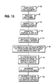
- the master controller 66 includes software which computes the time required for the document 14 to travel, with reference to the sensor 64, between the reference edge 14A (time 67B) and the midpoint of the test symbol 12A (time 67E). The software in the master controller 66 then determines the test symbol distance by utilizing the time difference between these two values (time 67B) and the midpoint of the test symbol 12A (time 67E) and by multiplying by the known step rate mentioned previously herein. This test symbol distance is best shown in relation to Fig. 12. As shown by block 92 in Fig. 13, this is repeated for a plurality of test documents 14. Another step, indicated by block 94 in Fig. 13, involves the master controller 66 calculating an average test symbol distance for all of the test documents 14. It is to be noted that the average test symbol distance represents the average distance between the reference edge 14A and the midpoint of the test symbol 12A for a plurality of test documents 14.
- Another step, as indicated by block 96 in Fig. 13, is to determine a further distance, the distance between the preselected heating element 62 and the reference edge 14A.
- the reference edge 14A (Figs. 7 and 12) represents the location of the sensor 64
- the heating element 62 (#190) represents the midpoint heating element 62 when the test symbol 12 is printed on the document 14.
- the average test symbol distance also represents the average distance between sensor 64 and heating element 62 (#190).
- the master controller 66 includes software which provides a means for determining the further distance by determining the number of heating elements 62 which would fall within the average test symbol distance by dividing the average test symbol distance by the known pitch distance between heating elements 62.
- Another step includes the master controller 66 using the average test symbol distance to determine the distance of each heating element 62, relative to the sensor 64, of the print member 56 using the fixed pitch distance (0.0165 cm) between each heating element 62.
- the master controller 66 stores the average test symbol distance and each locations of each heating element 62 as a binary number in EEPROM 68.
- the next step (block 100 of Fig. 13) is to determine the calibration distance using the above information.
- the calibration distance is the distance that the printer 10 has to be calibrated in order to print data 12 at the specified distance B from the reference edge 14A of the document 14.
- the master controller 66 determines the calibration distance by comparing the specified distance B, which is stored in EEPROM 68, to the average test symbol distance mentioned above. As will be described in detail later herein, the calibration distance can be further adjusted, for example, to compensate for inaccuracies in stopping the reference edge 14A of document 14 at sensor 64.
- the calibration distance is stored in EEPROM 68.
- the final step (block 102 in Fig. 13) is to calibrate the printer 10 to account for the calibration distance.
- the Master controller 66 makes coarse calibration adjustments by adjusting the location of document 14 at the print station C by using the document stepping motor 22.
- the master controller 66 includes software which calculates the number of full or half steps which would be necessary to account for the calibration distance by dividing the calibration distance by the known full and half step distance of the document stepping motor 22.
- Master controller 66 energizes document stepping motor 22 in full and/or half steps to stop document 14 early or late at the print station C so that the heating element 62 selected to print the leading edge of the first character of data 12 on the document 14 will be properly aligned at the specified distance B from the reference edge 14A of document 14.
- the master controller 66 makes fine calibration adjustments by selectively energizing the heating elements 62 on print head 56.
- the master controller 66 includes software which provides means for enabling the master controller 66 to determine the exact heating elements 62 of print member 56 which can be energized to adjust for some or all of the excess calibration distance which was not adjusted for by using the document stepping motor 22.
- the software in the master controller 66 determines the number of heating elements 62 which are equivalent to the calibration distance by dividing the excess calibration distance, if any, by the known pitch distance between each heating element 62.
- the software in the master controller 66 adds or subtracts the number of heating elements 62 determined above from the known location of the midpoint heating element 62 in order to account for the excess calibration distance.
- document stepping motor 22 is used to make coarse calibration adjustments to printer 10 to correct for calibration distances of 0.0635 cm or greater.
- the heating elements 62 of print member 56 are used to make fine calibration adjustments of between 0.0165 cm and 0.0635 cm. Calibration adjustments of less than 0.0165 cm are disregarded as acceptable error. The calibration of printer 10 will be described in detail later herein.
- test symbol 12A was printed (block 88 in Fig. 13) using heating elements #185-#195 (Figs. 7 and 12) on five test documents 14.
- actual five sample test symbol distances between sensor 64 and the midpoint of the test symbol 12A were determined (blocks 90 and 92 in Fig. 13) in the manner described earlier herein to be 0.368 cm, 0.389 cm, 0.34 cm, 0.35 cm, and 0.4 cm.
- the master controller 66 would compute the average test symbol distance (block 94 in Fig. 13) between the sensor 64 and the midpoint of the test symbol 12A of 0.369 cm.
- the master controller 66 would then determine the distance between the sensor 64 and the preselected heating elements (block 96 in Fig. 13). The master controller 66 would then calculate the relative distance between the sensor 64 and each heating element 62 (block 98 in Fig. 13) using the known pitch distance between each heating element 62 of 0.0165 cm. The master controller 66 stores this number in EEPROM 68 and uses this information to determine the calibration distance (block 100 in Fig. 13) and to calibrate the printer 10 (block 102 in Fig. 13) in the following manner.
- heating element 62 (#18) be used to print the leading edge of the first character of data 12
- the master controller 66 would determine the distance between heating element 62 (#190), which is the midpoint of the test symbol 12A, and heating element 62 (#18) to be used. In the present example, this distance would be 2.84 cm ((190-18) x 0.0165 pitch distance).
- a calibration distance (block 100 in Fig. 13) between sensor 64 and heating element 62 (#18) can then be calculated as 2.47 cm (2.84-0.369).
- the printer 10 will then be calibrated (block 102 in Fig. 13) to account for this distance so that when the document 14 is processed, the document 14 is advanced in track 18 so as to position the document so that heating element 62 (#18) is placed over the location of the document 14 where it is desired to effect the printing.
- the master controller 66 energizes the document stepper motor 22 in full steps of 0.127 cm or half steps of 0.0635 cm to make coarse calibration adjustments of greater than 0.0635 cm.
- the document stepping motor 22 would advance the document 14 forward a total of 3.238 cm (25 full motor steps or 3.175 cm and 1 half motor step or 0.0635 cm). This leaves an excess calibration distance of 0.025 cm (3.26 cm -3.235 cm).
- the master controller 66 selectively energizes one or more heating elements 62 on the print member 56 to make fine calibration adjustments of less than 0.635 cm in the preferred embodiment.
- the software in the master controller 66 would divide the 0.025 cm excess calibration distance by the pitch distance of 0.0165 cm to determine one (rounded) heating element 62 which represents the excess calibration distance.
- the master controller 66 software would add one heating element location to the heating element beginning with heating element 62 (#18) to account for most of the excess calibration distance.
- master controller 66 would energize heating element 62 (#19), rather than heating element 62 (#18) to account for the excess calibration distance.
- Excess calibration distances of less than the pitch distance (0.0165 cm) of the heating elements 62 are disregarded as accepted error, as mentioned previously herein. Consequently, the leftover calibration distance of 0.0089 cm is disregarded.
- a typical document 14 enters the print station C (Figs. 2, 6, and 8) and is moved to the sensor 64 at which time it is stopped. Errors result from the reference edge 14A of document 14 not stopping at the exact instant that it is sensed by sensor 64.
- the master controller includes a timer 63 (Fig. 2) which is used to calibrate the printer 10 to account for these errors.
- the timer 63 provides an elapsed time count for each motor phase pulse (not shown) of the document stepping motor 22 at the start of each full step of the motor 22.
- the master controller 66 immediately halts the timer 63.
- the elapsed time count on the timer represents both the amount of time that the document drive motor 22 remained energized and the distance the document 14 traveled past sensor 64 before the sensor 64 sensed the reference edge 14A.
- the additional calibration distance is determined by using the elapsed time count for the portion of the full step completed when the document 14 was stopped at sensor 64 as a percentage of the elapsed time count for a full step.
- the elapsed time count for a full step of document stepper motor 22 corresponds to 0.040 milliseconds and the elapsed time count measured when the document 14 was halted corresponds to 0.016 milliseconds
- master controller 66 it would be determined by master controller 66 that the document 14 traveled 40% (0.016ms/0.040ms) of a full step or 0.05 cm (0.127 cm full step distance x .40) before the document 14 actually stopped at the sensor 64. Consequently, an additional calibration distance of 0.076 cm (0.127-0.05) will result.
- the reference edge 14A of the document 14 would travel 0.076 cm farther than desired before the leading edge of the first character of data 12 is printed at the specified distance B (Fig. 4) from the reference edge 14A on the document 14.
- the master controller 66 can account for this 0.076 cm error by selectively energizing heating elements 62 in print member 56 which are closer to heating element 62 (#1), for example, or by energizing the document stepping motor 22, in the manner described previously herein.
- the printer 10 can be calibrated using the above method to account for manufacturing tolerances which cause the print member 56 to be located at a distance from the sensor 64 which is different from the specified distance B.
- the manufacturing tolerances can arise from, for example, separate mounting of the print member 56 on the arm 46 and the sensor 64 onto the track 18.
- the preferred embodiment of this invention also permits the stopping position of the document 14 at the print station C (Figs. 2, 6, 8, and 10) and the selection of heating elements 62 to be varied so as to utilize different heating elements 62 in the printing of data 12 on document 14. Utilizing the invention in this way prolongs the useful life of the print member 62.
- Fig. 11 shows a typical environment in which this invention might be used.
- One such environment includes a check endorser 72 having a housing 74 in which printer 10 is mounted by suitable fasteners (not shown).
- a plurality of checks 80 are stored in a check storage tray 82.
- printer 10 is mounted downstream from check storage tray 82.
- printer 10 is calibrated using the method described above so that data 12 is printed at substantially the preselected area A on the documents 14.
- the checks can be transferred mechanically from the tray 82 to the document track 18 where they are then transported to the print station C at printer 10.
- a teller or bank employee can use keyboard 76 to cause data 12 to be printed on the checks 80.
- After the checks 80 are processed they are moved downstream through track 18 to a check collector compartment 78 which collects the processed checks 80.
Landscapes
- Accessory Devices And Overall Control Thereof (AREA)
- Record Information Processing For Printing (AREA)
- Recording Measured Values (AREA)
Abstract
Description
- This invention relates generally to a document printer. In particular, the invention relates to a method for calibrating a printer to print data at a specified distance from a reference edge of a document moving through a print station.
- Printing apparatuses have been developed for many uses, including the printing of various information in various type fonts, such as E13B, OCRA and OCRB, on paper checks, for example. In most instances, it is desired or even required that the data be printed at a specific location or area on the check. For example, the American National Standards Institute (ANSI) has established standards that require a specified distance be maintained between a reference edge of the check and the first data character printed thereon. A typical example is the printing of MICR data in E13B font for which the ANSI specification requires the leading edge of the first character to be located in a character field beginning at 0.794 cm ± 0.159 cm from the reference edge of the check. In printers of the past, the print station would have to be manually calibrated to print data in the desired character field on the check. The check would be positioned at the print station and data or a test symbol would be printed thereon. A manufacturing or repair person (hereinafter field engineer) would usually observe where the data was actually being printed on the check and would then manually adjust or calibrate the print station so that the leading edge of the first character of data was printed beginning at the desired location. This process is time consuming, expensive, and leads to inaccurate results due to human error.
- There is, therefore, a present need to provide a method for calibrating a printer which is inexpensive, which can easily be performed, and which is not time consuming.
- An object of this invention is to provide a method for calibrating a printer to conform to various printing standards, thereby eliminating the need to have a field engineer manually adjust the location of the print means relative to the sensing means.
- According to the invention, there is provided a method for calibrating a printer to print data in a character field beginning at a specified distance from a reference edge of a document moving through said printer; said method being characterized by the steps of: (a) advancing a test document towards a sensing means and stopping said document in response to the detection of the reference edge of said document by said sensing means, (b) printing a test symbol on said test document with a print member having a line of equally spaced heating elements, extending parallel to the direction of movement of a document, said test symbol having a midpoint which is printed by a preselected heating element; (c) determining a test symbol distance which is the distance between said reference edge and the midpoint of said test symbol, (d) repeating steps and at least one time using a different test document; (e) calculating an average test symbol distance by averaging the test symbol distances determined in steps (c) and (d); (f) calculating a further distance representing the length of the maximum number of heating elements which would fall within said test symbol distance; (g) determining a calibration distance which is the difference between said further distance determined in step (f) and said average test symbol distance; and (h) calibrating said printer so as to cause a document to be positioned for commencement of a printing operation with its leading edge spaced a certain distance from the nearest heating element which is to be used in a print operation, said certain distance being adjusted in dependence on said calibration distance.
- The present invention advantageously provides an inexpensive method of calibrating a printer which can be performed speedily and more easily than prior art methods.
- An embodiment of the present invention will now be described with reference to the accompanying drawings, wherein:
- Fig. 1 is a top view of a prior art print station;
- Fig. 2 is a perspective view of a printer in which a preferred embodiment of this invention may be used;
- Fig. 3 is a perspective view showing a double cam, pivot arm, and print member which are part of the printer shown in Fig. 2;
- Fig. 4 is a front view of a document, showing data which may be printed on the document and also showing a preselected area which begins at a specified distance from a reference edge of the document;
- Fig. 5 is a front view of a test document, showing a test symbol printed at substantially the specified distance from the reference edge of the document;
- Fig. 6 is a fragmentary side view of the invention, showing an end of the document track shown in Fig. 2 with a document therein and also showing a print ribbon;
- Fig. 7 is a front view of a thermal print member included in the printer shown in Fig. 1, when looking in the direction of arrow E in Fig. 3, showing a row of heating elements of the print member and also showing the leading edge of the document and the direction of movement of the document;
- Fig. 8, which is shown on the same sheet as Fig. 6, is a fragmentary top view of a portion of the printer shown in Fig. 2, showing the document in the document track at a print station;
- Fig. 9 is a front view of the document with the test symbol printed thereon;
- Fig. 9A is a general voltage waveform corresponding to the document and the test symbol shown in Fig. 9;
- Fig. 10, which is shown on the sheet containing Figs. 4 and 5, is an enlarged view of the test symbol shown in Fig. 5, showing the matrix of dots which form the test symbol;
- Fig. 11 is a general perspective view of a typical environment in which this invention may be used;
- Fig. 12 is a top general diagrammatic view of the print station, showing an enlarged view of the print station and the general relationship among a sensor, the document, and the print member; and
- Fig. 13 is a general schematic view of a general method of calibrating the printer.
- Before discussing a preferred embodiment of this invention, a brief explanation of a prior art method of calibrating a printer will now be described. Fig. 1 shows a top view of a prior art print station A of a printer. The print station A includes a sensor B located opposite a thermal printer C. A document E having a reference edge E1 is located at the print station A between the sensor B and the thermal printer C. As illustrated, the thermal printer C has print elements t1 through t320. A distance D2 represents a preferred distance from the reference edge E1 in which it is desired to begin printing a first character of data (not shown). In the prior art printers, a field engineer would cause a document E to be moved past the sensor B a known distance D1. A character F would be printed on the document E using, for example, an impact typewheel C and an opposing hammer (not shown). The field engineer would remove the document E from the print station A and visually observe the distance between the reference edge E1 and the leading edge F1 of the character F. Such engineer would usually compare the location of the leading edge F1 of the character F to a desired location from the reference edge E1, indicated by the distance D2. The field engineer would then calibrate the printer to account for the distance D3 by manually altering the relative position between sensor B and the typewheel C so that, when another document E is moved the distance D1 past the sensor B and the typewheel is energized to print the first character of data, the leading edge of the character would be printed beginning at the distance D2.
- Fig. 2 is a perspective view of a preferred thermal printer, hereinafter designated generally as
printer 10, in which a preferred embodiment of this invention may be used. The function ofprinter 10 is to print monetary amounts or other data 12 (Fig. 4) on adocument 14. It is to be noted that thedocument 14 can be any suitable commercial document, like a check. As best shown in Fig. 5, thedocument 14 could be a test document which is generally the same size and shape as the check, for example, except that it is blank. A function ofprinter 10 is to printdata 12 in a preselected area, indicated by arrow A in Fig. 4, on thetest document 14. Theprinter 10 can also print atest symbol 12A (Fig. 5) which is used during the calibration ofprinter 10. It is to be noted that the preselected area A begins at a specified distance, indicated by arrow B in Fig. 4, fromreference edge 14A. - The printer 10 (Fig. 2) comprises a
base 16 which is a casting made of aluminum. Theprinter 10 also includes adocument track 18 in whichdocument 14 may travel to a print station, designated generally by arrow C in Figs. 2, 6, and 8. Thetrack 18 has first andsecond track walls track 18 has a generally "L"-shaped flange 18C which is secured tobase 16 by suitable fasteners (not shown). - The printer 10 (Fig. 2) also includes a drive means 20 for controlling the movement of
document 14 intrack 18 and for moving thedocument 14 to the print station C. The drive means 20 includes adocument stepping motor 22, printercam drive motor 24, first andsecond drive rollers second pinch rollers dual surface cam 32, and atiming belt 34. Thedocument stepping motor 22 and printercam drive motor 24 are capable of making full steps of 0.127 cm and 0.0041 cm respectively, and thedocument stepping motor 22 is capable of making half steps of 0.0635 cm. Thedocument stepping motor 22 is operatively coupled to the first andsecond drive rollers timing belt 26. The first andsecond drive rollers track wall 18A ofdocument track 18. The first andsecond pinch rollers track wall 18B and opposite the first andsecond drive rollers second pinch rollers drive rollers document 14 intrack 18. - The printer
cam drive motor 24 is operatively coupled to thedual surface cam 32 bytiming belt 34. Thedual surface cam 32 has acrown surface 32A and aradial surface 32B, and thedual surface cam 32 is mounted onaxle 42 and is secured thereto by C-clip 44. In a preferred embodiment,axle 42 is cast as part ofbase 16. As best shown in Figs. 2 and 3, apivot arm 46 includes acam follower member 50 which is secured to thepivot arm 46 by ascrew 54. Thecam follower member 50 follows thecrown surface 32A ofdual surface cam 32 and causes thepivot arm 46 to pivot aboutpivot members 46A and 46B in an arc indicated by the arcuately-shaped double arrow F in Fig. 3. As described later herein, theradial surface 32B ofdual surface cam 32 engages a platen 84 which forces thedocument 14 against aprint member 56. Thepivot arm 46 has pivot members 46a and 46b which are pivotally mounted in mounting supports 48a and 48b, respectively, ofbase 16. In a preferred embodiment, spring 52 (Fig. 2) is secured betweenpivot arm 46 andbase 16 for biasingcam follower member 50 against thecrown surface 32A ofdual surface cam 32. For an understanding of the operation ofdual surface cam 32, the reader is referred to U.S. Patent No. 4,818,126 which is also incorporated herein by reference. - The print member 56 (Fig. 3) is mounted in the
pivot arm 46 and is secured thereto by tworesilient detents 49. A thermal transfer print ribbon 58 (Fig. 6) lies between theprint member 56 anddocument 14, as best shown in Fig. 6. It is to be noted that when it is desired to printdata 12 ondocument 14, theradial surface 32B ofdual surface cam 32 forces a platen 84 (shown diagrammatically in Fig. 3) againstdocument 14 which is forced against thermaltransfer print ribbon 58 andprint member 56 whereuponprint member 56 is energized to printdata 12 ondocument 14. The platen 84 is arcuately shaped to enable it to maintain constant pressure against theprint member 56 as theprint member 56 is pivoted along a prescribed arc. In a preferred embodiment, theprint member 56 is a one row printhead model TX-C6A8-001E, manufactured by Matsushita Corporation of Japan. The print member 56 (Fig. 7) is comprised of asingle line 60 of 320heating elements 62. In a preferred embodiment, eachheating element 62 is generally rectangular and has a width of approximately 0.014 cm and a height of approximately 0.0198 cm. As shown in Fig. 7, eachheating element 62 has a pitch of 0.0165 cm. Eachheating element 62 can be individually and selectively energized by a master controller 66 (Fig. 2). - The printer 10 (Fig. 2) also includes a means for optically sensing, for example, the
reference edge 14A ofdocument 14 and thetest symbol 12A. The means for sensing includes areflective sensor 64 which is mounted directly ontrack wall 18A oftrack 18 and is mounted opposite to theprint member 56. In a preferred embodiment, thesensor 64 has a narrow beam angle for accurate detection of thereference edge 14A. Thesensor 64 is also positioned near the centre of theprint member 56 so that thedocument 14 will traverse a majority ofheating elements 62 when thedocument 14 is stopped at the print station C. As will be described later herein, during the calibration process, thetest symbol 12A is printed on thetest document 14 byprint member 56, and thedocument 14 is inverted and placed in thetrack 18 so that thetest symbol 12A faces thesensor 64. The height of thetest document 14 is chosen so that thesensor 64 is properly aligned with the midpoint oftest symbol 12A printed ondocument 14. In a preferred embodiment, thesensor 64 is a conventional optical reflective sensor having an associated mirror 64a (Fig. 8), and thesensor 64 generates a voltage signal proportional to the light reflection it senses. Figs. 2 and 9 show an analog to digital converter or A/D converter 70 operatively coupled betweensensor 64 and amaster controller 66. In the embodiment being described, themaster controller 66 is a model 8032 controller, manufactured by Intel Corporation. Themaster controller 66 can be programmed and loaded with software to perform the functions described hereinafter. The analog output fromsensor 64 is inputted to the A/D converter 70 which transmits a corresponding binary signal to themaster controller 66. Fig. 9A shows atypical voltage waveform 67 for atypical test document 14 as it passes thesensor 64.Waveform 67 changes from a high voltage level attime 67A to a low voltage level attime 67B when thesensor 64 is unblocked and blocked, respectively, bydocument 14. Thesensor 64 also senses the range of voltage levels attimes 67C-67D which represent thetest symbol 12A, andmaster controller 66 determines the midpoint which occurs approximately attime 67E.Sensor 64 also senses the trailingedge 14B ofdocument 14 which is represented by the voltage going from a low voltage attime 67F to a high voltage at time 67G. - Finally,
printer 10 includes a means for controlling or master controller for controlling the operation of theprinter 10. The master controller 66 (Figs. 2 and 9) is operatively coupled to document steppingmotor 22, printercam drive motor 24,print member 56,sensor 64, and A/D converter 70 by suitable conductors 65 (Fig. 2). Themaster controller 66 includes read-only memory (ROM) 67, a random-access memory (RAM) 69, and a nonvolatile electronically erasable programmable read only memory (EEPROM) 68. TheEEPROM 68 stores conventional software which controls the operation ofprinter 10 and which enables theprinter 10 to printdata 12, includingtest symbol 12A, ondocument 14 and which also enables the field engineer to calibrate theprinter 10. TheEEPROM 68 can also be programmed to store information, such as, for example, data corresponding to the preselected area A (Fig. 4) and the specified distance B. TheROM 67 orRAM 69 can be used, for example, to store the location of a givenheating element 62 relative to the position of thesensor 64 ofprint member 56. - The printing of a
test symbol 12A on adocument 14 will now be illustrated in relation to Figs. 5 and 10. Themaster controller 66 energizesprint drive motor 22 to movecam 32 in the direction of arrow G in Fig. 2 so that thecrown surface 32A ofcam 32 engagescam follower member 50, thereby positioning theprint member 56 towards the top of thedocument 14 located at the print station C. Theheating elements 62 ofprint member 56 print a first row of dots at a time towards the bottom ofdocument 14. This row forms the width of thetest symbol 12A. Themaster controller 66 then energizes the printercam drive motor 24 which causes thedual surface cam 32 to rotate in the direction of arrow G in Fig. 2. The rotation of thecrown surface 32A ofdual surface cam 32 causes thepivot arm 46 to pivot vertically upward in an arc which in turn causesprint member 56 to pivot downward in the opposite direction. Themaster controller 66 then energizes theheating elements 62 to print a second row of dots ondocument 14. This process continues until the last row of dots is printed on thedocument 14, thereby forming the height of thetest symbol 12A. This matrix of rows and columns of dots forms the test symbol, as can best be seen in relation to Fig. 10. - Before describing in detail the operation of a preferred embodiment of this invention, an overview of the invention may be useful. It is not uncommon to find that the
sensor 64 in theprinter 10 is mounted in an unknown relationship relative to theheating elements 62 of theprint member 56. Under ideal circumstances, it would be desirable to mount thesensor 64 an exact distance from, for example, themiddle heating element 62 ofprint member 56. However, this is not practical to do because of, for example, manufacturing tolerances in assembling theprinter 10. Consequently, there will be an unknown distance, hereafter referred to as the calibrating distance, between thesensor 64 and apreselected heating element 62 on theprint member 54. In order to avoid having to manually adjust the relative position of thesensor 64 andprint member 56 in theprinter 10 to make the calibration distance equal to the specified distance B, the present invention permits the distance betweensensor 64 and a knownheating element 62 to be determined. Using this distance information, the distance between thesensor 64 and everyother heating element 62 is determined by themaster controller 66. This is effected by printing thetest symbol 12A on thetest document 14 with certain knownheating elements 62, as will be described later herein. In general, the distance between thereference edge 14A and the midpoint of thetest symbol 12A is then determined by using thesensor 64. Because thereference edge 14A is located at thesensor 64 when thetest symbol 12A is printed on thedocument 14, themaster controller 66 can determine the distance between thesensor 64 and the preselectedheating elements 62 used to print the test symbol 12a, and in particular the distance between the reference edge 14a located at thesensor 64 and theheat element # 190 located at the midpoint of thetest symbol 12A. Themaster controller 66 then determines the distance between thesensor 64 and everyother heat element 62 on theprint member 56 because theheat elements 62 are located a precise pitch distance apart. Once these distances are known, themaster controller 66 stores the information inROM 67 orRAM 69. As will be described later herein, themaster controller 66 uses this information, as well as information regarding the location of thereference edge 14A, to make coarse and/or fine calibration adjustments so that the leading edge of the first character ofdata 12 is printed at precisely the preselected area A beginning at the specified distance B from thereference edge 14A. The master controller makes coarse calibration adjustments by energizing thedocument stepping motor 22 to cause thedocument 14 to stop either early or late at the print station C, and it makes fine calibration adjustments by selectively energizingindividual heating elements 62 ofprint member 56. Thus, themaster controller 66 can effect the calibration of theprinter 10 to adjust for the calibration distance without having to manually adjust the physical relationship or location of thesensor 64 orprint member 56. - The method of operation of a preferred embodiment of this invention will now be described in greater detail in relation to Fig. 13. A first step, indicated by
block 86, is to position a test document 14 (Fig. 5) in document track 18 (Fig. 2) when it is desired to calibrateprinter 10. Themaster controller 66 energizes document steppingmotor 22 to move thetest document 14 at a first predetermined rate of speed towards the print station C (Figs. 2, 6, and 8) in the direction of arrow D in Fig. 2. Thesensor 64 senses thereference edge 14A oftest document 14 at whichtime master controller 66 causes document steppingmotor 22 to stop thedocument 14. Themaster controller 66 then energizes thedocument stepping motor 22 to reverse the direction of movement ofdocument 14. In a preferred embodiment, thedocument 14 is moved in a reverse direction away fromsensor 64 until thereference edge 14A is approximately 3 millimeters upstream from thesensor 64. Themaster controller 66 then causesdocument stepping motor 22 to advancedocument 14 forward at a second predetermined rate of speed which is slower than the first predetermined rate of speed until thereference edge 14A is again sensed at print station C, whereuponmaster controller 66 causes document steppingmotor 22 to stopdocument 14. A typical first predetermined rate of speed is 0.127 cm step per 3 milliseconds. In a preferred embodiment, the first and second rates of speed are accomplished by thedocument stepping motor 22 advancing thedocument 14 in full and/or half steps, respectively. This process of advancing thedocument 14 forward at the second slower predetermined rate of speed permits themaster controller 66 to get a more accurate alignment ofreference edge 14A ofdocument 14 and thesensor 64. - After
document 14 is positioned in this manner, another step (block 88 in Fig. 13) includes printing thetest symbol 12A ondocument 14 with a preselected set of heating elements 62 (Fig. 7). By way of illustration, heating elements #185 to #195 may be preselected to print a row or line of dots (Fig. 10) ondocument 14 to form the width of thetest symbol 12A, as described above. Theprint member 56 would then be pivoted through an arc and another line of dots would be printed using the same preselectedheating elements 62. As best shown in Fig. 10, this process continues until the entire matrix of dots is printed to form thetest symbol 12A. Thetest symbol 12A is printed darker than the background ofdocument 14 on which it is printed so that it can be easily sensed by thesensor 64. - As shown by
block 90 in Fig. 13, the next step in this method of calibration is to determine the distance between thesensor 64 and thecentre heating element 62 used to print thetest symbol 12A in order to provide test symbol distance. After thetest symbol 12A is printed on thetest document 14, thetest document 14 is removed fromtrack 18, inverted (bottom to top and front to back), and reinserted into thetrack 18 upstream fromsensor 64 so thattest symbol 12A facestrack wall 18A. Themaster controller 66 then energizesdocument stepping motor 22 to move thedocument 14 down thetrack 18 until thetest symbol 12A passes thesensor 64. Thedocument 14 is then reversed in thetrack 18 bydocument stepping motor 22 until thereference edge 14A is approximately 3 millimeters upstream fromsensor 64. Thedocument 14 is then incremented forward and thesensor 64, which is coupled to A/D converter 70 (Figs. 2 and 9), begins taking measurement samples until well after thetest symbol 12A has passedsensor 64. In a preferred embodiment, the sample rate of the A/D converter 70 is made equal to the pitch of theheating elements 62 ofthermal printhead 56 which results in a sample rate of 8 samples per 0.127 cm step. As a result of this sampling, differing digital values corresponding to the time (Fig. 9A) when thesensor 64 senses, for example, no document (time 67A), thereference edge 14A (time 67B), and midpoint of thetest symbol 12A, (time 67E) are stored in theRAM 69. Themaster controller 66 includes software which computes the time required for thedocument 14 to travel, with reference to thesensor 64, between thereference edge 14A (time 67B) and the midpoint of thetest symbol 12A (time 67E). The software in themaster controller 66 then determines the test symbol distance by utilizing the time difference between these two values (time 67B) and the midpoint of thetest symbol 12A (time 67E) and by multiplying by the known step rate mentioned previously herein. This test symbol distance is best shown in relation to Fig. 12. As shown byblock 92 in Fig. 13, this is repeated for a plurality of test documents 14. Another step, indicated byblock 94 in Fig. 13, involves themaster controller 66 calculating an average test symbol distance for all of the test documents 14. It is to be noted that the average test symbol distance represents the average distance between thereference edge 14A and the midpoint of thetest symbol 12A for a plurality of test documents 14. - Another step, as indicated by
block 96 in Fig. 13, is to determine a further distance, the distance between thepreselected heating element 62 and thereference edge 14A. Notice that thereference edge 14A (Figs. 7 and 12) represents the location of thesensor 64, and the heating element 62 (#190) represents themidpoint heating element 62 when thetest symbol 12 is printed on thedocument 14. The average test symbol distance also represents the average distance betweensensor 64 and heating element 62 (#190). Using thedocument stepping motor 22 pitch distance mentioned above, themaster controller 66 includes software which provides a means for determining the further distance by determining the number ofheating elements 62 which would fall within the average test symbol distance by dividing the average test symbol distance by the known pitch distance betweenheating elements 62. Another step (block 98 in Fig. 13) includes themaster controller 66 using the average test symbol distance to determine the distance of eachheating element 62, relative to thesensor 64, of theprint member 56 using the fixed pitch distance (0.0165 cm) between eachheating element 62. Themaster controller 66 stores the average test symbol distance and each locations of eachheating element 62 as a binary number inEEPROM 68. - The next step (block 100 of Fig. 13) is to determine the calibration distance using the above information. The calibration distance is the distance that the
printer 10 has to be calibrated in order to printdata 12 at the specified distance B from thereference edge 14A of thedocument 14. Themaster controller 66 determines the calibration distance by comparing the specified distance B, which is stored inEEPROM 68, to the average test symbol distance mentioned above. As will be described in detail later herein, the calibration distance can be further adjusted, for example, to compensate for inaccuracies in stopping thereference edge 14A ofdocument 14 atsensor 64. The calibration distance is stored inEEPROM 68. - The final step (block 102 in Fig. 13) is to calibrate the
printer 10 to account for the calibration distance. TheMaster controller 66 makes coarse calibration adjustments by adjusting the location ofdocument 14 at the print station C by using thedocument stepping motor 22. Themaster controller 66 includes software which calculates the number of full or half steps which would be necessary to account for the calibration distance by dividing the calibration distance by the known full and half step distance of thedocument stepping motor 22.Master controller 66 energizes document steppingmotor 22 in full and/or half steps to stopdocument 14 early or late at the print station C so that theheating element 62 selected to print the leading edge of the first character ofdata 12 on thedocument 14 will be properly aligned at the specified distance B from thereference edge 14A ofdocument 14. Themaster controller 66 makes fine calibration adjustments by selectively energizing theheating elements 62 onprint head 56. Themaster controller 66 includes software which provides means for enabling themaster controller 66 to determine theexact heating elements 62 ofprint member 56 which can be energized to adjust for some or all of the excess calibration distance which was not adjusted for by using thedocument stepping motor 22. The software in themaster controller 66 determines the number ofheating elements 62 which are equivalent to the calibration distance by dividing the excess calibration distance, if any, by the known pitch distance between eachheating element 62. Because themidpoint heating element 62 used to print thetest symbol 12A is known, the software in themaster controller 66 adds or subtracts the number ofheating elements 62 determined above from the known location of themidpoint heating element 62 in order to account for the excess calibration distance. In a preferred embodiment,document stepping motor 22 is used to make coarse calibration adjustments toprinter 10 to correct for calibration distances of 0.0635 cm or greater. Theheating elements 62 ofprint member 56 are used to make fine calibration adjustments of between 0.0165 cm and 0.0635 cm. Calibration adjustments of less than 0.0165 cm are disregarded as acceptable error. The calibration ofprinter 10 will be described in detail later herein. - The following example illustrates the above method. Assume that the
test symbol 12A was printed (block 88 in Fig. 13) using heating elements #185-#195 (Figs. 7 and 12) on fivetest documents 14. Assume further that the actual five sample test symbol distances betweensensor 64 and the midpoint of thetest symbol 12A were determined (blocks master controller 66 would compute the average test symbol distance (block 94 in Fig. 13) between thesensor 64 and the midpoint of thetest symbol 12A of 0.369 cm. As mentioned previously herein, themaster controller 66 would then determine the distance between thesensor 64 and the preselected heating elements (block 96 in Fig. 13). Themaster controller 66 would then calculate the relative distance between thesensor 64 and each heating element 62 (block 98 in Fig. 13) using the known pitch distance between eachheating element 62 of 0.0165 cm. Themaster controller 66 stores this number inEEPROM 68 and uses this information to determine the calibration distance (block 100 in Fig. 13) and to calibrate the printer 10 (block 102 in Fig. 13) in the following manner. If it were desired that heating element 62 (#18) be used to print the leading edge of the first character ofdata 12, then themaster controller 66 would determine the distance between heating element 62 (#190), which is the midpoint of thetest symbol 12A, and heating element 62 (#18) to be used. In the present example, this distance would be 2.84 cm ((190-18) x 0.0165 pitch distance). A calibration distance (block 100 in Fig. 13) betweensensor 64 and heating element 62 (#18) can then be calculated as 2.47 cm (2.84-0.369). As will be described later herein, theprinter 10 will then be calibrated (block 102 in Fig. 13) to account for this distance so that when thedocument 14 is processed, thedocument 14 is advanced intrack 18 so as to position the document so that heating element 62 (#18) is placed over the location of thedocument 14 where it is desired to effect the printing. - As mentioned previously herein, it may be desirable or even necessary to print the leading edge of the first character of
data 12 at the specified distance B (Figs. 4 and 12) from thereference edge 14A ofdocument 14. Consequently, it may be necessary to add the specified distance B to the calibration distance determined inblock 100 of Fig. 13 and described earlier herein. If it were desired that the leading edge of the first character ofdata 12 to be printed, for example, be located 0.794 cm from thereference edge 14A ofdocument 14, then in the example being described, the software in themaster controller 66 would calculate the calibration distance of 3.26 cm (2.47 + 0.79). The calibration process (block 102 in Fig. 13) is continued as follows. - As mentioned previously herein, the
master controller 66 energizes thedocument stepper motor 22 in full steps of 0.127 cm or half steps of 0.0635 cm to make coarse calibration adjustments of greater than 0.0635 cm. Thedocument stepping motor 22 would advance thedocument 14 forward a total of 3.238 cm (25 full motor steps or 3.175 cm and 1 half motor step or 0.0635 cm). This leaves an excess calibration distance of 0.025 cm (3.26 cm -3.235 cm). Themaster controller 66 selectively energizes one ormore heating elements 62 on theprint member 56 to make fine calibration adjustments of less than 0.635 cm in the preferred embodiment. In this example, the software in themaster controller 66 would divide the 0.025 cm excess calibration distance by the pitch distance of 0.0165 cm to determine one (rounded)heating element 62 which represents the excess calibration distance. In the example being described, themaster controller 66 software would add one heating element location to the heating element beginning with heating element 62 (#18) to account for most of the excess calibration distance. Thus,master controller 66 would energize heating element 62 (#19), rather than heating element 62 (#18) to account for the excess calibration distance. Excess calibration distances of less than the pitch distance (0.0165 cm) of theheating elements 62 are disregarded as accepted error, as mentioned previously herein. Consequently, the leftover calibration distance of 0.0089 cm is disregarded. - During normal processing of
documents 14, like checks, further adjustments with respect to the calibration distance, referred to inblock 100 of Fig. 13, may be necessary because of the inaccuracies arising from not accurately stopping thereference edge 14A at thesensor 64. Atypical document 14 enters the print station C (Figs. 2, 6, and 8) and is moved to thesensor 64 at which time it is stopped. Errors result from thereference edge 14A ofdocument 14 not stopping at the exact instant that it is sensed bysensor 64. The master controller includes a timer 63 (Fig. 2) which is used to calibrate theprinter 10 to account for these errors. Thetimer 63 provides an elapsed time count for each motor phase pulse (not shown) of thedocument stepping motor 22 at the start of each full step of themotor 22. At the instant thereference edge 14A ofdocument 14 is detected bysensor 64, themaster controller 66 immediately halts thetimer 63. The elapsed time count on the timer represents both the amount of time that thedocument drive motor 22 remained energized and the distance thedocument 14 traveledpast sensor 64 before thesensor 64 sensed thereference edge 14A. The additional calibration distance is determined by using the elapsed time count for the portion of the full step completed when thedocument 14 was stopped atsensor 64 as a percentage of the elapsed time count for a full step. For example, if the elapsed time count for a full step ofdocument stepper motor 22 corresponds to 0.040 milliseconds and the elapsed time count measured when thedocument 14 was halted corresponds to 0.016 milliseconds, then it would be determined bymaster controller 66 that thedocument 14 traveled 40% (0.016ms/0.040ms) of a full step or 0.05 cm (0.127 cm full step distance x .40) before thedocument 14 actually stopped at thesensor 64. Consequently, an additional calibration distance of 0.076 cm (0.127-0.05) will result. If theprinter 10 is not calibrated to account for this error, then thereference edge 14A of thedocument 14 would travel 0.076 cm farther than desired before the leading edge of the first character ofdata 12 is printed at the specified distance B (Fig. 4) from thereference edge 14A on thedocument 14. Themaster controller 66 can account for this 0.076 cm error by selectively energizingheating elements 62 inprint member 56 which are closer to heating element 62 (#1), for example, or by energizing thedocument stepping motor 22, in the manner described previously herein. - It should be noted that the
printer 10 can be calibrated using the above method to account for manufacturing tolerances which cause theprint member 56 to be located at a distance from thesensor 64 which is different from the specified distance B. The manufacturing tolerances can arise from, for example, separate mounting of theprint member 56 on thearm 46 and thesensor 64 onto thetrack 18. Because the dot size and pitch of theheating elements 62 used to print a character ofdata 12 ondocument 14 are known, the preferred embodiment of this invention also permits the stopping position of thedocument 14 at the print station C (Figs. 2, 6, 8, and 10) and the selection ofheating elements 62 to be varied so as to utilizedifferent heating elements 62 in the printing ofdata 12 ondocument 14. Utilizing the invention in this way prolongs the useful life of theprint member 62. Somewhat similar arrangements for selective energization of thermal printing elements are disclosed in U.S. Patent No. 4,595,935 and U.S. Patent No. 4,625,216, which are incorporated herein by reference. - Fig. 11 shows a typical environment in which this invention might be used. One such environment includes a
check endorser 72 having ahousing 74 in whichprinter 10 is mounted by suitable fasteners (not shown). A plurality ofchecks 80 are stored in acheck storage tray 82. As is shown,printer 10 is mounted downstream fromcheck storage tray 82. Before documents are processed,printer 10 is calibrated using the method described above so thatdata 12 is printed at substantially the preselected area A on thedocuments 14. When it is desired to processchecks 80, the checks can be transferred mechanically from thetray 82 to thedocument track 18 where they are then transported to the print station C atprinter 10. A teller or bank employee can usekeyboard 76 to causedata 12 to be printed on thechecks 80. After thechecks 80 are processed, they are moved downstream throughtrack 18 to acheck collector compartment 78 which collects the processed checks 80. - Various changes or modifications in the invention described may occur to those skilled in the art without departing from the spirit or scope of the invention. For example, in a preferred embodiment the calibration process mentioned above proceeds along a horizontal direction; however, the same process could be employed to calibrate a printer in a vertical direction to set the character height from a bottom edge of the
document 14. The above description of the invention is intended to be illustrative and not limiting, and it is not intended that the invention be restricted thereto but that it be limited only by the true spirit and scope of the appended claims.
Claims (12)
- A method for calibrating a printer (10) to print data in a character field (A) beginning at a specified distance from a reference edge (14A) of a document (14) moving through said printer said method being characterized by the steps of: (a) advancing a test document towards a sensing means (64) and stopping said document in response to the detection of the reference edge of said document by said sensing means, (b) printing a test symbol on said test document with a print member (56) having a line of equally spaced heating elements (62), extending parallel to the direction of a document, said test symbol having a midpoint which is printed by a preselected heating element (#190); (c) determining a test symbol distance which is the distance between said reference edge (14A) and the midpoint (#190) of said symbol (12A); (d) repeating steps (a), (b) and (c) at least one time using a different test document; (e) calculating an average test symbol distance by averaging the test symbol distances determined in steps (c) and (d); (f) calculating a further distance representing the length of the maximum number of heating elements which would fall within said test symbol distance; (g) determining a calibration distance which is the difference between said further distance determined in step (f) and said average test symbol distance; and (h) calibrating said printer so as to cause a document to be positioned for commencement of a printing operation with its leading edge spaced a certain distance from the nearest heating element which is to be used in a print operation, said certain distance being adjusted in dependence on said calibration distance.
- A method according to claim 1, characterized in that said step (a) is effected by the steps of: (a1) moving said test document (14) in a first direction toward said sensing means (64) at a predetermined rate of speed; (a2) sensing the reference edge (14A) of said test document; and (a3) stopping said test document when said step (a2) is effected.
- A method according to claim 2, characterized in that said step (a) further includes the steps of: (a4) moving said test document (14) in a second direction away from said sensing means (64); (a5) moving said test document (14) in said first direction toward said sensing means (64) at a second rate of speed which is less than said predetermined rate of speed so as to more accurately determine the reference edge of the document; and (a6) repeating said step (a2) and step (a3).
- A method according to either claim 1 or 3, characterized in that said step (f) further includes the step of: (f1) adjusting said calibration distance to account for an inaccurate determination of said reference edge (14A).
- A method according to any preceding claim characterized in that said step (a) is effected by incrementing a stepping motor (22) in full or half steps.
- A method according to any preceding claim, characterized in that step (b) is performed with a dot matrix thermal printer (56) having at least one row (60) of heating elements (62) which are positioned in a line which is normal to said reference edge (14a).
- A method according to any preceding claim, characterized in that said step (c) further includes the step of: (c2) inverting said document so that said test symbol is reversed in order to obtain a measurement of the distance between the reference edge of the document and the midpoint of said test symbol as printed in step (b).
- A method according to any preceding claim, characterized in that said step (b) is effected by the step of: (b1) selecting a first set of heating elements (#185 to #195) from said plurality of heating elements (62) to print said test symbol (12A) on said test document (14A).
- A method according to any one of the preceding claims 5 to 8, characterized in that said step (h) is effected by the step of: (h1) utilizing said stepping motor (22) to calibrate the printer to account for calibration distances greater than 0.0635 cm.
- A method according to any preceding claim, characterized in that said step (h) is effected by the step of: (h1) utilizing at least one heating element of said print member to account for calibration distances between 0.0165 cm and 0.0635 cm.
- A method according to claim 9, characterized in that said step (h1) is further effected by the step of: computing the number of full and half steps of the document stepping motor (22) which are needed to position the document (14A) so that the leading edge of the first character of data is printed at said specified distance from the reference edge of the document.
- A method according to either claim 10 or 11, characterized in that said step (h1) is further effected by the step of: computing the exact heating element (62) which must be energized to effect calibrating the printer after taking into account the specified distance.
Applications Claiming Priority (2)
| Application Number | Priority Date | Filing Date | Title |
|---|---|---|---|
| US470452 | 1990-01-26 | ||
| US07/470,452 US4960336A (en) | 1990-01-26 | 1990-01-26 | Apparatus and method for calibrating printing at a specified distance from a document edge |
Publications (3)
| Publication Number | Publication Date |
|---|---|
| EP0449403A2 true EP0449403A2 (en) | 1991-10-02 |
| EP0449403A3 EP0449403A3 (en) | 1991-10-09 |
| EP0449403B1 EP0449403B1 (en) | 1996-01-10 |
Family
ID=23867687
Family Applications (1)
| Application Number | Title | Priority Date | Filing Date |
|---|---|---|---|
| EP91300570A Expired - Lifetime EP0449403B1 (en) | 1990-01-26 | 1991-01-25 | A method for calibrating a printer |
Country Status (5)
| Country | Link |
|---|---|
| US (1) | US4960336A (en) |
| EP (1) | EP0449403B1 (en) |
| JP (1) | JP2867073B2 (en) |
| CA (1) | CA2018058A1 (en) |
| DE (1) | DE69116196T2 (en) |
Cited By (3)
| Publication number | Priority date | Publication date | Assignee | Title |
|---|---|---|---|---|
| EP0570167A2 (en) * | 1992-05-11 | 1993-11-18 | Hewlett-Packard Company | Method and apparatus for regulating print density in an ink-jet printer |
| EP0735738A2 (en) * | 1995-03-30 | 1996-10-02 | Hewlett-Packard Company | Facsimile scan position calibration apparatus and method |
| WO2000051017A2 (en) * | 1999-02-26 | 2000-08-31 | Electronics For Imaging, Inc. | Automatic margin alignment |
Families Citing this family (16)
| Publication number | Priority date | Publication date | Assignee | Title |
|---|---|---|---|---|
| US5346322A (en) * | 1989-04-24 | 1994-09-13 | Brother Kogyo Kabushiki Kaisha | Printing device having paper feed control |
| JP3182802B2 (en) * | 1991-07-25 | 2001-07-03 | ブラザー工業株式会社 | Paper edge detection device for printer |
| US5276478A (en) * | 1992-05-19 | 1994-01-04 | Eastman Kodak Company | Method and apparatus for optimizing depth images by adjusting print spacing |
| US5397276A (en) * | 1993-09-17 | 1995-03-14 | R. R. Donnelley & Sons Company | Pulse encoder resolution adjustment apparatus |
| DE4401900C2 (en) * | 1994-01-24 | 1998-07-09 | Heidelberger Druckmasch Ag | Method for controlling a print image position on a sheet in a sheet printing machine |
| US5524995A (en) * | 1994-11-14 | 1996-06-11 | Pitney Bowes, Inc. | Apparatus and method for detecting the position of envelopes in a mailing machine |
| US5956469A (en) * | 1995-06-19 | 1999-09-21 | Eastman Kodak Company | Selecting a calibration function for a digital printer which minimizes an error criterion |
| US5823693A (en) * | 1995-11-30 | 1998-10-20 | Intermec Ip Corp. | Gapless label media and printing apparatus for handling same |
| GB2312304B (en) * | 1996-04-18 | 1999-12-29 | Ibm | Improvements in printing |
| US5915865A (en) * | 1996-12-05 | 1999-06-29 | Intermec Ip Corp. | Method and apparatus for compensating for printer top-of-form and image stretch errors |
| US5871288A (en) * | 1996-12-24 | 1999-02-16 | Pitney Bowes Inc. | Method for customer selectable module size for an information based indicia |
| US5890818A (en) * | 1997-06-30 | 1999-04-06 | Pitney Bowes Inc. | Pixel splitting to improve bar code readability |
| US20030145750A1 (en) * | 2002-02-02 | 2003-08-07 | Terence Chee Sung Chang | Print cutter calibration method and apparatus |
| KR100529336B1 (en) * | 2003-07-15 | 2005-11-17 | 삼성전자주식회사 | Method for detecting an edge portion of printing medium and Edge detection apparatus |
| US7474321B2 (en) * | 2005-08-03 | 2009-01-06 | Carestream Health, Inc. | Thermal recording method and system employing edge printing |
| US7675622B2 (en) * | 2005-11-14 | 2010-03-09 | Hewlett-Packard Development Company, L.P. | Determining a media feature using a photovoltaic cell and an electroluminescent light panel |
Citations (3)
| Publication number | Priority date | Publication date | Assignee | Title |
|---|---|---|---|---|
| US4778288A (en) * | 1985-11-29 | 1988-10-18 | Sharp Kabushiki Kaisha | Automatic print zone setting system |
| US4812999A (en) * | 1986-02-28 | 1989-03-14 | Nec Corporation | Data output control system |
| US4861175A (en) * | 1985-07-13 | 1989-08-29 | Brother Kogyo Kabushiki Kaisha | Serial printer control system |
Family Cites Families (12)
| Publication number | Priority date | Publication date | Assignee | Title |
|---|---|---|---|---|
| US4311399A (en) * | 1977-02-09 | 1982-01-19 | Sycor, Inc. | Method and apparatus for setting and varying margins and line spacing on data printers |
| US4394092A (en) * | 1981-12-21 | 1983-07-19 | Ncr Canada Ltd. - Ncr Canada Ltee | Method and apparatus for high speed thermal printing |
| US4555617A (en) * | 1982-12-23 | 1985-11-26 | Ncr Canada Ltd.-Ncr Canada Ltee | Concurrent, image-based, reject-re-entry repair system and method |
| US4818126A (en) * | 1983-12-14 | 1989-04-04 | Ncr Canada Ltd - Ncr Canada Ltee | Method and apparatus for thermally printing data in special fonts on documents like checks |
| JPH064352B2 (en) * | 1984-08-08 | 1994-01-19 | 東京電気株式会社 | Label printer |
| US4595935A (en) * | 1984-08-14 | 1986-06-17 | Ncr Canada Ltd. | System for detecting defective thermal printhead elements |
| US4573058A (en) * | 1985-05-24 | 1986-02-25 | Ncr Canada Ltd - Ncr Canada Ltee | Closed loop thermal printer for maintaining constant printing energy |
| US4625216A (en) * | 1985-08-05 | 1986-11-25 | Ncr Canada Ltd. | Thermal printhead life extension technique |
| US4731524A (en) * | 1985-10-11 | 1988-03-15 | Ncr Canada Ltd. - Ncr Canada Ltee | Real time item processing apparatus using a thermal encoder |
| US4758966A (en) * | 1986-05-05 | 1988-07-19 | Ncr Canada Ltd. - Ncr Canada Ltee | Thermal printing apparatus and method |
| US4827286A (en) * | 1986-12-27 | 1989-05-02 | Canon Kabushiki Kaisha | Thermal transfer printer |
| US4783667A (en) * | 1987-07-17 | 1988-11-08 | Ncr Canada Ltd - Ncr Canada Ltee | Printing of angled and curved lines using thermal dot matrix printer |
-
1990
- 1990-01-26 US US07/470,452 patent/US4960336A/en not_active Expired - Lifetime
- 1990-06-01 CA CA002018058A patent/CA2018058A1/en not_active Abandoned
- 1990-11-30 JP JP2330919A patent/JP2867073B2/en not_active Expired - Fee Related
-
1991
- 1991-01-25 DE DE69116196T patent/DE69116196T2/en not_active Expired - Fee Related
- 1991-01-25 EP EP91300570A patent/EP0449403B1/en not_active Expired - Lifetime
Patent Citations (3)
| Publication number | Priority date | Publication date | Assignee | Title |
|---|---|---|---|---|
| US4861175A (en) * | 1985-07-13 | 1989-08-29 | Brother Kogyo Kabushiki Kaisha | Serial printer control system |
| US4778288A (en) * | 1985-11-29 | 1988-10-18 | Sharp Kabushiki Kaisha | Automatic print zone setting system |
| US4812999A (en) * | 1986-02-28 | 1989-03-14 | Nec Corporation | Data output control system |
Cited By (10)
| Publication number | Priority date | Publication date | Assignee | Title |
|---|---|---|---|---|
| EP0570167A2 (en) * | 1992-05-11 | 1993-11-18 | Hewlett-Packard Company | Method and apparatus for regulating print density in an ink-jet printer |
| EP0570167A3 (en) * | 1992-05-11 | 1994-05-18 | Hewlett Packard Co | Method and apparatus for regulating print density in an ink-jet printer |
| US5473351A (en) * | 1992-05-11 | 1995-12-05 | Hewlett-Packard Corporation | Method and apparatus for regulating print density in an ink-jet printer |
| EP0735738A2 (en) * | 1995-03-30 | 1996-10-02 | Hewlett-Packard Company | Facsimile scan position calibration apparatus and method |
| EP0735738A3 (en) * | 1995-03-30 | 1999-05-06 | Hewlett-Packard Company | Facsimile scan position calibration apparatus and method |
| US6016207A (en) * | 1995-03-30 | 2000-01-18 | Hewlett-Packard Company | Facsimile scan position calibration apparatus and method |
| WO2000051017A2 (en) * | 1999-02-26 | 2000-08-31 | Electronics For Imaging, Inc. | Automatic margin alignment |
| WO2000051017A3 (en) * | 1999-02-26 | 2000-12-07 | Electronics For Imaging Inc | Automatic margin alignment |
| US6226419B1 (en) | 1999-02-26 | 2001-05-01 | Electronics For Imaging, Inc. | Automatic margin alignment using a digital document processor |
| AU758295B2 (en) * | 1999-02-26 | 2003-03-20 | Electronics For Imaging, Inc. | Automatic margin alignment |
Also Published As
| Publication number | Publication date |
|---|---|
| CA2018058A1 (en) | 1991-07-26 |
| JP2867073B2 (en) | 1999-03-08 |
| EP0449403B1 (en) | 1996-01-10 |
| DE69116196D1 (en) | 1996-02-22 |
| EP0449403A3 (en) | 1991-10-09 |
| US4960336A (en) | 1990-10-02 |
| JPH03222784A (en) | 1991-10-01 |
| DE69116196T2 (en) | 1996-08-29 |
Similar Documents
| Publication | Publication Date | Title |
|---|---|---|
| EP0449403B1 (en) | A method for calibrating a printer | |
| US4795281A (en) | Self-correcting printer-verifier | |
| US4699531A (en) | Self-correcting printer-verifier | |
| JP3484245B2 (en) | Shuttle-type printer printing system and shuttle-type printer operating method | |
| EP0540244B1 (en) | Automatic print cartridge alignment sensor system | |
| EP0540243B1 (en) | Print cartridge alignment in paper axis | |
| US6126345A (en) | Sheet feeding device and correction method of sheet feed amount in the sheet feeding device | |
| EP0540245B1 (en) | Print cartridge bidirectional alignment in carriage axis | |
| EP0539812B1 (en) | Print cartridge cam actuator linkage | |
| GB2163582A (en) | Label printer | |
| US6101426A (en) | Sheet feeding device and correction method of sheet feed amount in the sheet feeding device | |
| US4934845A (en) | Apparatus and method for controlling paper feeding in a printer | |
| US5518324A (en) | Platen to print head gap adjustment arrangement | |
| EP0183535B1 (en) | Self-correcting printer-verifier | |
| US5635704A (en) | Self-adjusting optical sensing system for financial and retail printers | |
| US4531132A (en) | Method and apparatus for thermally printing data in special fonts on documents like checks | |
| JPH06262823A (en) | Platen gap automatically adjusting device in printer | |
| US6601513B1 (en) | Motor control method and apparatus, time recorder having same and impact type printing apparatus | |
| CA1261035A (en) | Leading edge detection in self-correcting printer-verifiers | |
| CN103129160A (en) | Printing device provided with mechanism for correcting deformation of print medium | |
| JP3691578B2 (en) | Printer and printer gap error correction method | |
| US5046413A (en) | Method and apparatus for band printing with automatic home compensation | |
| US4665371A (en) | Character spacing circuit for controlling print hammer firing | |
| JPS63165723A (en) | Electronic price balance equipped with label printer | |
| JP3019124B2 (en) | Automatic platen gap adjustment device for printer |
Legal Events
| Date | Code | Title | Description |
|---|---|---|---|
| PUAI | Public reference made under article 153(3) epc to a published international application that has entered the european phase |
Free format text: ORIGINAL CODE: 0009012 |
|
| PUAL | Search report despatched |
Free format text: ORIGINAL CODE: 0009013 |
|
| AK | Designated contracting states |
Kind code of ref document: A2 Designated state(s): DE FR GB |
|
| AK | Designated contracting states |
Kind code of ref document: A3 Designated state(s): DE FR GB |
|
| 17P | Request for examination filed |
Effective date: 19920312 |
|
| RAP1 | Party data changed (applicant data changed or rights of an application transferred) |
Owner name: NCR INTERNATIONAL INC. |
|
| RAP1 | Party data changed (applicant data changed or rights of an application transferred) |
Owner name: AT&T GLOBAL INFORMATION SOLUTIONS INTERNATIONAL IN |
|
| 17Q | First examination report despatched |
Effective date: 19941220 |
|
| GRAA | (expected) grant |
Free format text: ORIGINAL CODE: 0009210 |
|
| AK | Designated contracting states |
Kind code of ref document: B1 Designated state(s): DE FR GB |
|
| REF | Corresponds to: |
Ref document number: 69116196 Country of ref document: DE Date of ref document: 19960222 |
|
| ET | Fr: translation filed | ||
| PLBE | No opposition filed within time limit |
Free format text: ORIGINAL CODE: 0009261 |
|
| STAA | Information on the status of an ep patent application or granted ep patent |
Free format text: STATUS: NO OPPOSITION FILED WITHIN TIME LIMIT |
|
| 26N | No opposition filed | ||
| REG | Reference to a national code |
Ref country code: FR Ref legal event code: CD |
|
| REG | Reference to a national code |
Ref country code: GB Ref legal event code: 746 Effective date: 20010116 |
|
| REG | Reference to a national code |
Ref country code: FR Ref legal event code: D6 |
|
| REG | Reference to a national code |
Ref country code: GB Ref legal event code: IF02 |
|
| PGFP | Annual fee paid to national office [announced via postgrant information from national office to epo] |
Ref country code: GB Payment date: 20050105 Year of fee payment: 15 |
|
| PGFP | Annual fee paid to national office [announced via postgrant information from national office to epo] |
Ref country code: FR Payment date: 20050131 Year of fee payment: 15 Ref country code: DE Payment date: 20050131 Year of fee payment: 15 |
|
| PG25 | Lapsed in a contracting state [announced via postgrant information from national office to epo] |
Ref country code: GB Free format text: LAPSE BECAUSE OF NON-PAYMENT OF DUE FEES Effective date: 20060125 |
|
| PG25 | Lapsed in a contracting state [announced via postgrant information from national office to epo] |
Ref country code: FR Free format text: LAPSE BECAUSE OF NON-PAYMENT OF DUE FEES Effective date: 20060131 |
|
| PG25 | Lapsed in a contracting state [announced via postgrant information from national office to epo] |
Ref country code: DE Free format text: LAPSE BECAUSE OF NON-PAYMENT OF DUE FEES Effective date: 20060801 |
|
| GBPC | Gb: european patent ceased through non-payment of renewal fee |
Effective date: 20060125 |
|
| REG | Reference to a national code |
Ref country code: FR Ref legal event code: ST Effective date: 20060929 |