EP0449390B1 - Method and equipment for the control of the distribution of pressure load applied to a material web - Google Patents
Method and equipment for the control of the distribution of pressure load applied to a material web Download PDFInfo
- Publication number
- EP0449390B1 EP0449390B1 EP91201220A EP91201220A EP0449390B1 EP 0449390 B1 EP0449390 B1 EP 0449390B1 EP 91201220 A EP91201220 A EP 91201220A EP 91201220 A EP91201220 A EP 91201220A EP 0449390 B1 EP0449390 B1 EP 0449390B1
- Authority
- EP
- European Patent Office
- Prior art keywords
- zone
- nip
- unit
- pressure
- set value
- Prior art date
- Legal status (The legal status is an assumption and is not a legal conclusion. Google has not performed a legal analysis and makes no representation as to the accuracy of the status listed.)
- Expired - Lifetime
Links
- 239000000463 material Substances 0.000 title claims abstract description 23
- 238000000034 method Methods 0.000 title claims abstract description 23
- 230000001105 regulatory effect Effects 0.000 claims abstract description 44
- 238000006243 chemical reaction Methods 0.000 claims abstract description 26
- 238000013178 mathematical model Methods 0.000 claims abstract description 5
- 238000005259 measurement Methods 0.000 claims description 9
- 238000003490 calendering Methods 0.000 claims description 4
- 230000000694 effects Effects 0.000 claims description 4
- 230000001276 controlling effect Effects 0.000 claims description 3
- 239000000314 lubricant Substances 0.000 claims description 2
- 230000002159 abnormal effect Effects 0.000 claims 1
- 238000010276 construction Methods 0.000 description 5
- 230000006835 compression Effects 0.000 description 4
- 238000007906 compression Methods 0.000 description 4
- 239000012530 fluid Substances 0.000 description 3
- 238000004364 calculation method Methods 0.000 description 2
- 230000001627 detrimental effect Effects 0.000 description 2
- 238000010586 diagram Methods 0.000 description 2
- 238000005461 lubrication Methods 0.000 description 2
- 239000011159 matrix material Substances 0.000 description 2
- XLYOFNOQVPJJNP-UHFFFAOYSA-N water Substances O XLYOFNOQVPJJNP-UHFFFAOYSA-N 0.000 description 2
- 230000004075 alteration Effects 0.000 description 1
- 238000005452 bending Methods 0.000 description 1
- 230000015572 biosynthetic process Effects 0.000 description 1
- 238000004590 computer program Methods 0.000 description 1
- 238000009499 grossing Methods 0.000 description 1
- 230000003993 interaction Effects 0.000 description 1
- 239000000203 mixture Substances 0.000 description 1
- 230000008092 positive effect Effects 0.000 description 1
- 238000007639 printing Methods 0.000 description 1
- 238000007670 refining Methods 0.000 description 1
- 230000003068 static effect Effects 0.000 description 1
Images




Classifications
-
- D—TEXTILES; PAPER
- D21—PAPER-MAKING; PRODUCTION OF CELLULOSE
- D21G—CALENDERS; ACCESSORIES FOR PAPER-MAKING MACHINES
- D21G1/00—Calenders; Smoothing apparatus
- D21G1/002—Opening or closing mechanisms; Regulating the pressure
- D21G1/004—Regulating the pressure
-
- D—TEXTILES; PAPER
- D21—PAPER-MAKING; PRODUCTION OF CELLULOSE
- D21F—PAPER-MAKING MACHINES; METHODS OF PRODUCING PAPER THEREON
- D21F3/00—Press section of machines for making continuous webs of paper
- D21F3/02—Wet presses
- D21F3/0209—Wet presses with extended press nip
- D21F3/0218—Shoe presses
-
- D—TEXTILES; PAPER
- D21—PAPER-MAKING; PRODUCTION OF CELLULOSE
- D21F—PAPER-MAKING MACHINES; METHODS OF PRODUCING PAPER THEREON
- D21F3/00—Press section of machines for making continuous webs of paper
- D21F3/02—Wet presses
- D21F3/06—Means for regulating the pressure
-
- D—TEXTILES; PAPER
- D21—PAPER-MAKING; PRODUCTION OF CELLULOSE
- D21G—CALENDERS; ACCESSORIES FOR PAPER-MAKING MACHINES
- D21G1/00—Calenders; Smoothing apparatus
- D21G1/002—Opening or closing mechanisms; Regulating the pressure
-
- D—TEXTILES; PAPER
- D21—PAPER-MAKING; PRODUCTION OF CELLULOSE
- D21G—CALENDERS; ACCESSORIES FOR PAPER-MAKING MACHINES
- D21G1/00—Calenders; Smoothing apparatus
- D21G1/002—Opening or closing mechanisms; Regulating the pressure
- D21G1/004—Regulating the pressure
- D21G1/0046—Regulating the pressure depending on the measured properties of the calendered web
Definitions
- the present invention concerns a method and a an equipment according to the preamble of claims 1 and 12, respectively.
- a dewatering press nip In paper machines and in after-treatment apparatuses for paper, several such rolls are used as form a dewatering press nip, a smoothing nip, or a calendering nip with a counter-roll.
- the distribution of the linear load in the nip i.e. the profile, in the axial direction remains invariable or that this profile can be adjusted as desired, e.g., in view of controlling the moisture profile and/or the thickness profile of the web in the transverse direction of the web, or any other, corresponding quality profile of the web.
- different adjustable-crown or variable-crown rolls are knonwn in prior art, by means of which the distribution of the linear load in a nip is controlled.
- variable-crown or adjustable-crown rolls for paper machines are known.
- these rolls comprise a massive, stationary roll axle and a roll mantle arranged revolving around the axle. Between the said axle and the mantle, glide-shoe arrangements and/or pressure-fluid chambers are fitted, which act upon the inner face of the mantle and which are divided or grouped in several parts or groups in the axial direction of the roll so that the axial profile of the mantle at the nip can be aligned or adjusted as desired.
- the nips formed by such rolls such as press nips or calendering nips, are loaded by means of loading forces applied to the axle journals of the variable-crown roll and of its counter-roll.
- variable-crown roll An example of a variable-crown roll to which the teachings of the method and the device in accordance with the present invention can be applied favourably is the variable-crown roll described in the applicant's US-A-4, 757, 585.
- glide shoes loaded by means of cylinders provided with common hydraulic supply zones are used for controlling the deflection of the variable-crown rolls.
- Each of the said zones is controlled by means of a zone-specific hydraulic valve.
- the number of glide shoes in different zones may be different from zone to zone in the way required by the purposeful control of the compression force between the variable-crown roll and its counter-roll.
- the number of the loading cylinders used in order to produce the nip pressure is, as a rule, one at each end of the roll axle, and the said cylinders produce the compression force together with the glide shoes.
- variable-crown rolls have become more and more extensively used both in paper machines and in paper refining machines and in various after-treatment devices for paper, which is partly due to the fact that ever higher quality requirements are imposed on the product that is being produced, i.e. as regards its various properties, the paper must be within ever stricter quality specifications both in the machine direction and in the transverse direction. At least one partial reason for the ever stricter quality criteria are the new copying and printing techniques, whose undisturbed operation requires uniform quality of paper.
- the variable-crown rolls are one component by means of which it is possible to have a positive effect on the said quality properties of paper.
- variable-crown rolls have been developed considerably in recent years, but the same cannot be said about the regulating systems of variable-crown rolls, which have, however, an entirely decisive importance when variable-crown rolls are used for the control of the quality properties of paper.
- variable-crown roll For example, if one thinks of a situation in which there are five pressure zones usable in a variable-crown roll, with the regulating systems known in prior art it is possible to set the linear load at five different points in accordance with the set values. If the length of the variable-crown roll is, e.g., 10 metres, the said points will be located about 2 metres apart from each other, and within the areas between the set points the linear loads remain entirely beyond control.
- the invention it is in practice possible to control the property profile of the web to be treated so that it follows the set property profile more accurately than in prior art, because the operator of the press shoe can set the set profile or goal profile of the compression force as accurately as possible so as to accomplish the property profile aimed at.
- This objective is achieved by means of the invention thereby that the goal profile of the linear load in the nip between the press shoe and the counter-member has been arranged settable at a considerably higher number of points in the transverse direction of the web to be treated as compared with the total number of independent pressure zones and loading cylinders in the press shoe adjustable in zones.
- the set values of the zone pressures of the press shoe are set substantially more densely in the transverse direction of the material web than what is required by the number of pressure zones available in the press shoes used.
- the said goal values are converted in accordance with the invention, in a way that is new in this environment of application, to guide values for zone pressures of the zone roll, and the said conversion is carried out expressly so that, by using the chosen zone pressure values, deviations from the linear-load distribution aimed at can be minimized.
- diagnostic and protection logic are integrated into the regulating system in accordance with the invention so that the detrimental effects of disturbances of operation can be minimized.
- variable-crown roll 10 to be regulated by means of the regulation system in accordance with the invention.
- the variable-crown roll 10 With its counter-roll 20, the variable-crown roll 10 forms a nip No, through which the material web W to be treated is passed.
- the nip No is, e.g., a nip in the dewatering press of a paper machine or a calendering nip either in a supercalender or in a so-called machine stack.
- the profile of the linear load in the nip No i.e. the distribution of the linear load in the transverse direction of the web W, is regulated by means of the variable-crown roll 10.
- the counter-roll 20 is provided with axle journals 21 a and 21 b, by means of which the roll 20 is journalled as revolving in its bearing supports 22a and 22b, which may be provided with loading members.
- the variable-crown roll 10 includes a massive central axle 11, around which a cylindrical roll mantle 13 is arranged revolving.
- Glide shoes which are loaded by means of pressure cylinders 15, act against the smooth inner face of the roll mantle 13.
- the pressure cylinders 15 are divided into zones 16, in which a certain zone pressure of hydraulic fluid, regulated by means of the regulating system of the present invention, is passed into each cylinder 15.
- the nip No is loaded from the axle journals 11 a and 11 b of the stationary central axle 11 of the variable-crown roll by means of loading cylinders 12a and 12b, into which pressures P a and P b of hydraulic fluid are passed, which said pressures are also regulated.
- the system includes a block 100, which comprises the zone conversion unit of the set value unit and from which the set values A of the zone pressures of the variable-crown roll 10 and of the pressures P a and P b are obtained, the total number of the said set values A being K.
- the said set values A are passed to the limiter block 200, in which the set values of the zone pressures are limited within chosen limit values.
- the limiter block 200 From the limiter block 200 the limited set values B of the pressures are obtained, whose number is K and which said values B are passed to an intelligent regulator unit 300, from which the flow signals C of valves are obtained, the number of the said flow signals C being K.
- the unit 400 is controlled, which said unit includes the pressure control valves 410 and the converters 420 (Fig. 3).
- the flow signals of valve pressures are obtained as feedback signals D, the number of the said flow signals being K and the said signals being measurement signals coming to the regulator unit 300.
- the valve pressures P are obtained, which are passed so as to make the pressures for the zones 16 in the variable-crown roll 10 as well as the pressures P a and P b for the hydraulic cylinders 12a and 12b that load the axle journals 11 a and 11 b of the variable-crown roll.
- the regulating system is further shown as including a feedback block 500, to which a series E of measurement signals is passed from a detector device 510, which measures the properties of the web W passing through the nip No, e.g. moisture or caliper, in the transverse direction of the web W.
- the feedback unit 500 controls the set value unit 100.
- the feedback unit 500 is not used in many of the applications of the invention.
- the distribution of the loading forces applied to the material web W passed in between the roll 10 adjustable in zones and the counter-roll 20 is controlled.
- a member other than a cylindrical roll face such as a band loop, against which the glide shoes 15 are pressed in accordance with the hydraulic pressures passed into the control zones 16.
- a member other than a cylindrical counter-face e.g. a moving band or a stationary member.
- the pressure signals converted to feedback signals D are connected to the intelligent regulator 300, which receives the set values of the zone pressures P as outgoing signals B of the limiter block 200.
- the intelligent regulator 300 includes a diagnostic block 310, a protection logic part 320, and single-channel regulators 340.
- the operation takes place in accordance with Fig. 3 when the roll 10 with its controls operates in accordance with what is expected, i.e. when the output pressures P of the valves 410 comply with the set values B of the zone pressures at the controlled accuracy.
- each pressure regulator 350...350+K operates independently from other corresponding regulators.
- the diagnostic part 310 of the intelligent regulator 300 notices the deviation by means of the converter unit 420 of the feedback signals D of the valves.
- the protection logic part 320 controls the set values B of the pressures in the regulators 350 of the regulator part 340 to a state purposeful in view of protecting the roll 10.
- the transfer of erroneous pressure set values A of the valves 410, which might damage the roll 10,to set values B of the intelligent regulator 300 is already prevented in advance.
- the desired set-value profile Q(Z) of the linear load is formed.
- the loading cylinders 12a and 12b are also included in the set zones Z.
- the number N of the set zones Z is substantially higher than the number K of the hydraulic valves 410 or equivalent, i.e. N » K, whereas the number of zones 16 is K-2, and the number of loading cylinders 12a and 12b is two.
- the number N of set zones Z is preferably chosen so that a corresponding number of linear-load estimation points in the material web W between the zone roll 10 and the counter-roll 20 is enough to illustrate the distribution of the linear load caused by each zone 16 in the material web W.
- the set values A 1 of the linear loads in zones are passed into the zone conversion block 120.
- the set values A 1 in accordance with the linear-load profile Q(Z) of the set zones Z are converted to set values A for the zone valves 410.
- information is needed on how the unit formed by the zone roll 10 and its counter-roll 20 as well as by the material web W behaves elastically depending on the zone pressures Py and on the loading pressures P a and P b .
- This information can be obtained theoretically and, if necessary, experimentally, and it can be presented in the form of a mathematical model, which is applied in the zone conversion block 120, e.g., in the form of a computer program.
- the zone conversion taking place in the zone conversion block 120, from the set zones Z (N pcs.) to the set values C (K pcs.) of the pressures for the zone valves 410, there is no direct unequivocal solution.
- the control system When the important marginal condition is imposed on the conversion taking place in the block 120 that by means of the set values C of the zone pressures Py to be carried into effect, the control system must produce a factual linear-load profile applied to the material web W which differs from the set linear-load profile Q(Z) as little as possible, the said conversion problem can be solved unequivocally.
- the conversion, to be carried out in the conversion block 120, of the set linear loads Q, ... Q N to set values Pi ...P K of zone pressures, wherein N > K can be accomplished in practice by applying the so-called pseudo-inverse theory, which is a method known in mathematics. In respect of this method, reference is made to the paper by James A. Cad- zow and Hinrich R. Martens: "Discrete-Time and Computer Control Systems", Sec. 7.6 "Minimum Energy Control", pp. 286 to 293, Prentice-Hall Inc., 1970, U.S.A.
- the relationship between the distribution of linear load Q(Z) and the zone pressures P is determined on the basis of the physical data of the roll and of the properties of the material web. This determination takes place, e.g., by illustrating the zone roll 10, the counter-roll 20, the nip No between them, and the material web W running through it by means of a simplified beam model, whereby an element model illustrating the nip is reached, i.e. a certain linear equation group, which can be solved by means of matrix algebra while taking the above marginal conditions into account.
- the operator of the regulating system in accordance with the invention may give the nip No the desired distribution of linear load Q(Z).
- the operator can directly control a quantity acting upon the quality of the paper, whereby it is possible to draw linear conclusions about the relationship between a performed control operation and the result that is obtained.
- the operator sets the desired linear-load profile Q(Z).
- the zone pressures and loading pressures needed in order to accomplish the linear-load distribution that was set are calculated by means of the said model illustrating the roll nip No.
- the on- line calculation required by the control in accordance with the model can be simplified to matrix multiplication.
- the controls can be calculated easily by means of a microcomputer.
- variable-crown roll 10 and the material web W running in the nip No impose limitations on the permitted alterations in the linear load per unit of length. Should the linear-load profile set by the operator attempt to cause excessively large pressure variations in the nip No, the control system restricts the control to the desired levels before it is carried into effect.
- the system in accordance with the invention may supervise the operation of the equipment. In failure situations that are serious in view of the equipment, the system controls the nip to a safe state. Thus, the control system does not permit controls that damage the zone roll 10 or the paper web W in any situation.
- the extended nip Np whose length is denoted with L o in Fig. 6, is formed between a hollow-faced 20' press roll 20 and a press shoe 10A.
- the paper web W runs through the nip Np between press felts 41 and 42 that receive water.
- an impervious band loop 40 acts against the glide face 35' of the glide piece 35 of the shoe 10A.
- a lubricant is fed through a pipe 37 in the direction of the arrows s, e.g. a lubrication oil or a mixture of water and lubrication oil.
- the press shoe 10A is supported on the end flange 31 of the frame beam 30.
- a cylinder block 32 is attached, which includes a series of cylinder bores 33i ...33 K in the direction of the longer dimension of the nip Np, of which said bores the bores 33 n and 33 n+ , are seen in Figures 6 and 7.
- a series of pistons 34i ...34 K is fitted, of which pistons the pistons 34 n and 34 n+l are seen in Figures 6 and 7.
- the sides of the pistons series 34 that face the nip Np are connected to the glide piece 35, which is elongate and sufficiently resilient in the direction of the cylinder-piston series 33,34, so that the pressure distribution in the nip Np can be adjusted and controlled by means of the pressures P1...Pn, Pn+1".Pk passed into the cylinder spaces 33.
- the said ratio k also depends on the material of the glide shoe 35.
- the pressures p adjusted by means of the regulating system in accordance with the invention are passed into the cylinders 33 via the series of pipes 38 and the bores 39.
- the pistons 34 are sealed by seal rings 36.
- the length of the glide piece 35 in the transverse direction corresponds to the width of the web W to be treated, and it is, as a rule, of an order of 5 to 10 m.
- the press roll 20 shown in Figures 6 and 7 may be substituted for by a corresponding shoe, so that the nip Np is formed between two opposite press shoes.
- the construction may be, e.g., similar to that described in Fig. 7 in the applicant's FI Patent No. 71,369.
- Fig. 1 shows such an embodiment variation of the invention in which a feedback block 500 is used.
- a detector unit 510 is placed, from which a series E of measurement signals is obtained, which is passed into the feedback and processing unit 500.
- the unit 500 again controls the unit 100 so that a series Q(Z) of set values is obtained directly or indirectly on the basis of the values measured from the web W.
- the detector unit 510 includes, e.g., N pcs. of measurement detectors 521... 520 + N.
- the detector unit 510 may also include more than N detectors, e.g. 2 x N, and in the unit 500 the necessary conversion, e.g.
- Some of the properties of the web W to be measured may be, e.g., its thickness (caliper), moisture, surface smoothness, glaze, or various combinations of the said measurements.
- the feedback block 500 described above and the detector units 510,520 are often not necessary or not even usable, and the invention can be accomplished mostly "with manual control" so that the operator of the system gives a series Q(Z) of set values, for which he receives the necessary information from the other measurement system belonging to the paper machine or to the after-treatment equipment and/or from the laboratory.
- the method and the device of the invention may also be applied to press shoe devices corresponding to a roll 10 adjustable in zones, which said shoe devices, as a rule, form a so-called extended nip with a counter-member, e.g. a roll or a second shoe device.
- press shoe devices are known in prior art, and therein it is possible to use glide shoes or glide-shoe groups, whose pressure-effect actuator is controlled by means of the regulating system of the present invention.
Landscapes
- Paper (AREA)
- Coating Apparatus (AREA)
- Blow-Moulding Or Thermoforming Of Plastics Or The Like (AREA)
- Rolls And Other Rotary Bodies (AREA)
- Control Of Fluid Pressure (AREA)
- Medicines Containing Material From Animals Or Micro-Organisms (AREA)
- Saccharide Compounds (AREA)
- Pharmaceuticals Containing Other Organic And Inorganic Compounds (AREA)
- Electrical Discharge Machining, Electrochemical Machining, And Combined Machining (AREA)
- Application Of Or Painting With Fluid Materials (AREA)
- Crystals, And After-Treatments Of Crystals (AREA)
- Preliminary Treatment Of Fibers (AREA)
- Rollers For Roller Conveyors For Transfer (AREA)
Abstract
Description
- The present invention concerns a method and a an equipment according to the preamble of
claims - Although the invention concerns conditions prevailing in the nip between a press shoe and a counter member it will be disclosed mainly with reference to a nip between a variable-crown roll and a counter member.
- In paper machines and in after-treatment apparatuses for paper, several such rolls are used as form a dewatering press nip, a smoothing nip, or a calendering nip with a counter-roll. In these purposes of use, it is important that the distribution of the linear load in the nip, i.e. the profile, in the axial direction remains invariable or that this profile can be adjusted as desired, e.g., in view of controlling the moisture profile and/or the thickness profile of the web in the transverse direction of the web, or any other, corresponding quality profile of the web. For this purpose, different adjustable-crown or variable-crown rolls are knonwn in prior art, by means of which the distribution of the linear load in a nip is controlled.
- In prior art, several different variable-crown or adjustable-crown rolls for paper machines are known. As a rule, these rolls comprise a massive, stationary roll axle and a roll mantle arranged revolving around the axle. Between the said axle and the mantle, glide-shoe arrangements and/or pressure-fluid chambers are fitted, which act upon the inner face of the mantle and which are divided or grouped in several parts or groups in the axial direction of the roll so that the axial profile of the mantle at the nip can be aligned or adjusted as desired. As a rule, the nips formed by such rolls, such as press nips or calendering nips, are loaded by means of loading forces applied to the axle journals of the variable-crown roll and of its counter-roll.
- An example of a variable-crown roll to which the teachings of the method and the device in accordance with the present invention can be applied favourably is the variable-crown roll described in the applicant's US-A-4, 757, 585.
- As is known in prior art, glide shoes loaded by means of cylinders provided with common hydraulic supply zones are used for controlling the deflection of the variable-crown rolls. Each of the said zones is controlled by means of a zone-specific hydraulic valve. The number of glide shoes in different zones may be different from zone to zone in the way required by the purposeful control of the compression force between the variable-crown roll and its counter-roll. The number of the loading cylinders used in order to produce the nip pressure is, as a rule, one at each end of the roll axle, and the said cylinders produce the compression force together with the glide shoes.
- Variable-crown rolls have become more and more extensively used both in paper machines and in paper refining machines and in various after-treatment devices for paper, which is partly due to the fact that ever higher quality requirements are imposed on the product that is being produced, i.e. as regards its various properties, the paper must be within ever stricter quality specifications both in the machine direction and in the transverse direction. At least one partial reason for the ever stricter quality criteria are the new copying and printing techniques, whose undisturbed operation requires uniform quality of paper. The variable-crown rolls are one component by means of which it is possible to have a positive effect on the said quality properties of paper.
- The mechanical constructions of variable-crown rolls have been developed considerably in recent years, but the same cannot be said about the regulating systems of variable-crown rolls, which have, however, an entirely decisive importance when variable-crown rolls are used for the control of the quality properties of paper.
- The prior-art control systems for variable-crown rolls involve the drawback that, even if the interactions of the compression forces produced by the zone pressures in the zone rolls on the different zones are taken into account, the operator of the roll has only a low number of zones which he can control and by means of which attempts are made to accomplish an even highly varied profile of properties in the transverse direction of the web. An example of such a control system in use at present is the control system in accordance with the German Patent DE 3,117,516.
- For example, if one thinks of a situation in which there are five pressure zones usable in a variable-crown roll, with the regulating systems known in prior art it is possible to set the linear load at five different points in accordance with the set values. If the length of the variable-crown roll is, e.g., 10 metres, the said points will be located about 2 metres apart from each other, and within the areas between the set points the linear loads remain entirely beyond control.
- It is an object of the present invention to develop the regulating systems of press shoes (variable-crown rolls) further so that the profile of linear load in the nip between the press shoe and its counter-member is adjustable more accurately without increasing the number of pressure zones. An increased number of zones would result in a more complicated construction of the press shoe and in an increased inclination to disturbances.
- It is a further object of the invention to provide such a regulating system in which a certain amount of "intelligence" can be integrated, such as diagnostic and protection of the operation of a roll so that the detrimental effects of various disturbances can be eliminated or at least minimized.
- In view of achieving the objectives given above and those that will come out later, the regulating method and equipment in accordance with the invention is mainly characterized by the features of
claims - Owing to the invention, it is in practice possible to control the property profile of the web to be treated so that it follows the set property profile more accurately than in prior art, because the operator of the press shoe can set the set profile or goal profile of the compression force as accurately as possible so as to accomplish the property profile aimed at. This objective is achieved by means of the invention thereby that the goal profile of the linear load in the nip between the press shoe and the counter-member has been arranged settable at a considerably higher number of points in the transverse direction of the web to be treated as compared with the total number of independent pressure zones and loading cylinders in the press shoe adjustable in zones.
- According to the invention, initially the set values of the zone pressures of the press shoe are set substantially more densely in the transverse direction of the material web than what is required by the number of pressure zones available in the press shoes used. Hereupon the said goal values are converted in accordance with the invention, in a way that is new in this environment of application, to guide values for zone pressures of the zone roll, and the said conversion is carried out expressly so that, by using the chosen zone pressure values, deviations from the linear-load distribution aimed at can be minimized.
- The above conversion from a higher number of given goal values to a lower number of guide values for zone pressures can be carried out by the so-called pseudo-inverse technique known from the mathematics of the treatment of matrices, which will be returned to below.
- According to a preferred embodiment of the invention, diagnostic and protection logic are integrated into the regulating system in accordance with the invention so that the detrimental effects of disturbances of operation can be minimized.
- In the following, the invention will be described in detail with reference to some exemplifying embodiments of the invention illustrated in the figures in the accompanying drawing, whereat the invention is not confined to the details of the said embodiments.
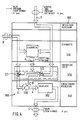
- Figure 1 shows the principle of a regulating system in accordance with the invention as a block diagram, applied to a variable-crown roll.
- Figure 2 shows the set value block, the zone conversion block, and the limiter block for linear load.
- Figure 3 shows the regulator, actuator, and feedback blocks of a system in accordance with the invention as well as the connection of the regulator to the variable-crown roll to be regulated and to the nip formed by the said roll.
- Figure 4 shows a more detailed embodiment of the regulator block in accordance with the invention as a block diagram.
- Figure 5 shows an embodiment of the regulators for the individual channels in the regulator block in accordance with the invention.
- Figure 6 is a vertical cross-sectional view in the machine direction of a so-called extended nip, being a subject of regulation of the invention, and Fig. 6 is at the same time a section VI-VI in Fig. 7.
- Figure 7 shows a section VII-VII in Fig. 6.
- To begin with, with reference to Figures 1 and 3, a brief description will be given of the construction and operation of a variable-
crown roll 10 to be regulated by means of the regulation system in accordance with the invention. With itscounter-roll 20, the variable-crown roll 10 forms a nip No, through which the material web W to be treated is passed. The nip No is, e.g., a nip in the dewatering press of a paper machine or a calendering nip either in a supercalender or in a so-called machine stack. The profile of the linear load in the nip No, i.e. the distribution of the linear load in the transverse direction of the web W, is regulated by means of the variable-crown roll 10. - The
counter-roll 20 is provided withaxle journals 21 a and 21 b, by means of which theroll 20 is journalled as revolving in its bearing supports 22a and 22b, which may be provided with loading members. The variable-crown roll 10 includes a massivecentral axle 11, around which acylindrical roll mantle 13 is arranged revolving. - Glide shoes, which are loaded by means of
pressure cylinders 15, act against the smooth inner face of theroll mantle 13. Thepressure cylinders 15 are divided intozones 16, in which a certain zone pressure of hydraulic fluid, regulated by means of the regulating system of the present invention, is passed into eachcylinder 15. Moreover, the nip No is loaded from theaxle journals central axle 11 of the variable-crown roll by means ofloading cylinders - To begin with, referring to Fig. 1, the general principles of the regulating system in accordance with the present invention will be described. The system includes a
block 100, which comprises the zone conversion unit of the set value unit and from which the set values A of the zone pressures of the variable-crown roll 10 and of the pressures Pa and Pb are obtained, the total number of the said set values A being K. The said set values A are passed to thelimiter block 200, in which the set values of the zone pressures are limited within chosen limit values. From thelimiter block 200 the limited set values B of the pressures are obtained, whose number is K and which said values B are passed to anintelligent regulator unit 300, from which the flow signals C of valves are obtained, the number of the said flow signals C being K. By means of the said signals C, theunit 400 is controlled, which said unit includes thepressure control valves 410 and the converters 420 (Fig. 3). From theunit 400, the flow signals of valve pressures are obtained as feedback signals D, the number of the said flow signals being K and the said signals being measurement signals coming to theregulator unit 300. From theunit 400, the valve pressures P are obtained, which are passed so as to make the pressures for thezones 16 in the variable-crown roll 10 as well as the pressures Pa and Pb for thehydraulic cylinders axle journals - In Fig. 1, the regulating system is further shown as including a
feedback block 500, to which a series E of measurement signals is passed from adetector device 510, which measures the properties of the web W passing through the nip No, e.g. moisture or caliper, in the transverse direction of the web W. Thefeedback unit 500 controls theset value unit 100. Thefeedback unit 500 is not used in many of the applications of the invention. - By means of the control system, the distribution of the loading forces applied to the material web W passed in between the
roll 10 adjustable in zones and thecounter-roll 20 is controlled. In stead of aroll 10 adjustable in zones, it is also possible to use a member other than a cylindrical roll face, such as a band loop, against which theglide shoes 15 are pressed in accordance with the hydraulic pressures passed into thecontrol zones 16. In stead of acounter-roll 20, it is also possible to use a member other than a cylindrical counter-face, e.g. a moving band or a stationary member. - By means of
converters 420, whose number is K, e.g. K = 10, measurement information is obtained on the pressures P in thezones 16 and in theloading cylinders intelligent regulator 300, which receives the set values of the zone pressures P as outgoing signals B of thelimiter block 200. Theintelligent regulator 300 again controls thehydraulic valves 410, whose number is K, e.g. K=10, by means of its control signals C, whose number is also K. - As part functions, the
intelligent regulator 300 includes adiagnostic block 310, aprotection logic part 320, and single-channel regulators 340. The operation takes place in accordance with Fig. 3 when theroll 10 with its controls operates in accordance with what is expected, i.e. when the output pressures P of thevalves 410 comply with the set values B of the zone pressures at the controlled accuracy. Thereat, eachpressure regulator 350...350+K operates independently from other corresponding regulators. - If the
roll 10 with its controls operates abnormally, thediagnostic part 310 of theintelligent regulator 300 notices the deviation by means of theconverter unit 420 of the feedback signals D of the valves. On the basis of the control data di received from thediagnostic part 310, theprotection logic part 320 controls the set values B of the pressures in theregulators 350 of theregulator part 340 to a state purposeful in view of protecting theroll 10. - In the
limiter block 200, the transfer of erroneous pressure set values A of thevalves 410, which might damage theroll 10,to set values B of theintelligent regulator 300 is already prevented in advance. Thereat, the pressure set values (Pj; j = 1,2,...K) of eachhydraulic valve 410 are limited between certain minimum and maximum pressures MIN (UM(Pj)), MAX (LIM(Pj)), wherein j = 1,2,...K. Moreover, in order to protect themantle 13 of thezone roll 10 from excessive bending, the differences between the set pressures in adjoiningzones 16 are limited to a level lower than the permitted limit APj:j+i > [ Pj-Pj+i], wherein j = 1,...,K-1. - In accordance with Fig. 2, the linear load of the
zone roll 10 is controlled by aset block 110 for the linear-load profile Q, for each set zone Z (Z =consecutive number 1...N of the zones), setting the desired linear load Q; of the zone (i = 1,2,...,N). In this way, in the nip No between thezone roll 10 and the counter-roll 20, the desired set-value profile Q(Z) of the linear load is formed. Theloading cylinders - It is a characteristic feature of the present invention that the number N of the set zones Z is substantially higher than the number K of the
hydraulic valves 410 or equivalent, i.e. N » K, whereas the number ofzones 16 is K-2, and the number ofloading cylinders - In the invention, the number N of set zones Z is preferably chosen so that a corresponding number of linear-load estimation points in the material web W between the
zone roll 10 and the counter-roll 20 is enough to illustrate the distribution of the linear load caused by eachzone 16 in the material web W. One advantageous choice for the number N of set zones Z is about twice the number K of hydraulic valves 410 (N = 2xK). As a rule, N = (1.5-3)xK. The above choice of the number N of set zones Z does not result in an unnecessarily high value of N either, in view of the operator's trouble and range of setting. - The number N of set zones is, as a rule, within the range of N = 5 to 50, preferably N = 10 to 20. The number K of the different adjustable pressure zones in a variable-
crown roll 10, which said zones include thehydraulic cylinders roll 10, if any, is as a rule within the range of K = 5 to 20, preferably K = 6 to 10. - In accordance with Fig. 2, the set values A1 of the linear loads in zones are passed into the
zone conversion block 120. In thezone conversion block 120 the set values A1 in accordance with the linear-load profile Q(Z) of the set zones Z are converted to set values A for thezone valves 410. In order that the conversion taking place in theblock 120 could be carried out, information is needed on how the unit formed by thezone roll 10 and its counter-roll 20 as well as by the material web W behaves elastically depending on the zone pressures Py and on the loading pressures Pa and Pb. This information can be obtained theoretically and, if necessary, experimentally, and it can be presented in the form of a mathematical model, which is applied in thezone conversion block 120, e.g., in the form of a computer program. For the zone conversion, taking place in thezone conversion block 120, from the set zones Z (N pcs.) to the set values C (K pcs.) of the pressures for thezone valves 410, there is no direct unequivocal solution. When the important marginal condition is imposed on the conversion taking place in theblock 120 that by means of the set values C of the zone pressures Py to be carried into effect, the control system must produce a factual linear-load profile applied to the material web W which differs from the set linear-load profile Q(Z) as little as possible, the said conversion problem can be solved unequivocally. In the invention, the conversion, to be carried out in theconversion block 120, of the set linear loads Q, ... QN to set values Pi ...PK of zone pressures, wherein N > K, can be accomplished in practice by applying the so-called pseudo-inverse theory, which is a method known in mathematics. In respect of this method, reference is made to the paper by James A. Cad- zow and Hinrich R. Martens: "Discrete-Time and Computer Control Systems", Sec. 7.6 "Minimum Energy Control", pp. 286 to 293, Prentice-Hall Inc., 1970, U.S.A. - The relationship between the distribution of linear load Q(Z) and the zone pressures P is determined on the basis of the physical data of the roll and of the properties of the material web. This determination takes place, e.g., by illustrating the
zone roll 10, the counter-roll 20, the nip No between them, and the material web W running through it by means of a simplified beam model, whereby an element model illustrating the nip is reached, i.e. a certain linear equation group, which can be solved by means of matrix algebra while taking the above marginal conditions into account. - Owing to the zone-pressure calculation programmed in the
block 120, the operator of the regulating system in accordance with the invention may give the nip No the desired distribution of linear load Q(Z). Thus, the operator can directly control a quantity acting upon the quality of the paper, whereby it is possible to draw linear conclusions about the relationship between a performed control operation and the result that is obtained. - On the basis of the measured transverse profile of the paper, the operator sets the desired linear-load profile Q(Z). The zone pressures and loading pressures needed in order to accomplish the linear-load distribution that was set are calculated by means of the said model illustrating the roll nip No. In spite of the complexity of the problem, the on- line calculation required by the control in accordance with the model can be simplified to matrix multiplication. The controls can be calculated easily by means of a microcomputer.
- The
mantle 13 of the variable-crown roll 10 and the material web W running in the nip No impose limitations on the permitted alterations in the linear load per unit of length. Should the linear-load profile set by the operator attempt to cause excessively large pressure variations in the nip No, the control system restricts the control to the desired levels before it is carried into effect. - The system in accordance with the invention may supervise the operation of the equipment. In failure situations that are serious in view of the equipment, the system controls the nip to a safe state. Thus, the control system does not permit controls that damage the
zone roll 10 or the paper web W in any situation. - In stead of regulating the roll nip No described above, by means of the regulating system in accordance with the invention, it is also possible to regulate a so-called extended nip Np of the sort shown in Figures 6 and 7 or of another, corresponding sort. The extended nip Np, whose length is denoted with Lo in Fig. 6, is formed between a hollow-faced 20'
press roll 20 and apress shoe 10A. The paper web W runs through the nip Np between press felts 41 and 42 that receive water. Moreover, animpervious band loop 40 acts against the glide face 35' of theglide piece 35 of theshoe 10A. To the inlet side between theband loop 40 and the glide face 35' of theglide piece 35, a lubricant is fed through a pipe 37 in the direction of the arrows s, e.g. a lubrication oil or a mixture of water and lubrication oil. - The
press shoe 10A is supported on theend flange 31 of theframe beam 30. Onto the top face of theflange 31, acylinder block 32 is attached, which includes a series of cylinder bores 33i ...33K in the direction of the longer dimension of the nip Np, of which said bores the bores 33n and 33n+, are seen in Figures 6 and 7. In the cylinder bores 33, a series of pistons 34i ...34K is fitted, of which pistons the pistons 34n and 34n+l are seen in Figures 6 and 7. The sides of the pistons series 34 that face the nip Np are connected to theglide piece 35, which is elongate and sufficiently resilient in the direction of the cylinder-piston series 33,34, so that the pressure distribution in the nip Np can be adjusted and controlled by means of the pressures P1...Pn, Pn+1".Pk passed into the cylinder spaces 33. - In Fig. 6, the length of the
glide piece 35 in the direction of running of the web W is denoted with L, and the thickness with H. If it is designated that L = k x H, theglide piece 35 is, as a rule, sufficiently flexible if k is within the range of k = 7 to 15, preferably k = 10 to 13. The said ratio k also depends on the material of theglide shoe 35. The pressures p adjusted by means of the regulating system in accordance with the invention are passed into the cylinders 33 via the series ofpipes 38 and thebores 39. The pistons 34 are sealed by seal rings 36. The length of theglide piece 35 in the transverse direction corresponds to the width of the web W to be treated, and it is, as a rule, of an order of 5 to 10 m. - The
press roll 20 shown in Figures 6 and 7 may be substituted for by a corresponding shoe, so that the nip Np is formed between two opposite press shoes. In such a case, the construction may be, e.g., similar to that described in Fig. 7 in the applicant's FI Patent No. 71,369. Moreover, reference is made to the said Finnish patent in respect of the construction and operation of the extended nip Np, such as the distribution of the pressure in the direction of running of the web W. - Fig. 1 shows such an embodiment variation of the invention in which a
feedback block 500 is used. In connection with the material web W to be treated, after the nip No in the direction of running of the web, adetector unit 510 is placed, from which a series E of measurement signals is obtained, which is passed into the feedback andprocessing unit 500. Theunit 500 again controls theunit 100 so that a series Q(Z) of set values is obtained directly or indirectly on the basis of the values measured from the web W. Thedetector unit 510 includes, e.g., N pcs. ofmeasurement detectors 521... 520 + N. Thedetector unit 510 may also include more than N detectors, e.g. 2 x N, and in theunit 500 the necessary conversion, e.g. formation of the average, is carried out in order to produce a series Q(Z) of set value signals. In stead of a static series ofdetectors 510, it is also possible to use a suitable detector device traversing across the material web W and giving either a continuous measurement signal or taking samples of the properties of the web W in its cross direction. - Some of the properties of the web W to be measured may be, e.g., its thickness (caliper), moisture, surface smoothness, glaze, or various combinations of the said measurements. The
feedback block 500 described above and the detector units 510,520 are often not necessary or not even usable, and the invention can be accomplished mostly "with manual control" so that the operator of the system gives a series Q(Z) of set values, for which he receives the necessary information from the other measurement system belonging to the paper machine or to the after-treatment equipment and/or from the laboratory. - Even though, above, the invention has been dealt with only with reference to a
roll 10 adjustable in zones, it is to be emphasized that, within the scope of protection of the invention, the method and the device of the invention may also be applied to press shoe devices corresponding to aroll 10 adjustable in zones, which said shoe devices, as a rule, form a so-called extended nip with a counter-member, e.g. a roll or a second shoe device. Such press shoe devices are known in prior art, and therein it is possible to use glide shoes or glide-shoe groups, whose pressure-effect actuator is controlled by means of the regulating system of the present invention. In connection with the press- shoe devices, it is possible to use flexible band loops and/or elastic bands in themselves known.
Claims (15)
Applications Claiming Priority (3)
| Application Number | Priority Date | Filing Date | Title |
|---|---|---|---|
| FI870774A FI76872C (en) | 1987-02-23 | 1987-02-23 | Method and apparatus for controlling zone rollers. |
| FI870774 | 1987-02-23 | ||
| EP88850060A EP0298057B1 (en) | 1987-02-23 | 1988-02-22 | Method and device for the control of a zone roll |
Related Parent Applications (1)
| Application Number | Title | Priority Date | Filing Date |
|---|---|---|---|
| EP88850060.0 Division | 1988-02-22 |
Publications (4)
| Publication Number | Publication Date |
|---|---|
| EP0449390A2 EP0449390A2 (en) | 1991-10-02 |
| EP0449390A3 EP0449390A3 (en) | 1992-07-08 |
| EP0449390B1 true EP0449390B1 (en) | 1994-08-31 |
| EP0449390B2 EP0449390B2 (en) | 1997-08-20 |
Family
ID=8524003
Family Applications (2)
| Application Number | Title | Priority Date | Filing Date |
|---|---|---|---|
| EP88850060A Expired - Lifetime EP0298057B1 (en) | 1987-02-23 | 1988-02-22 | Method and device for the control of a zone roll |
| EP91201220A Expired - Lifetime EP0449390B2 (en) | 1987-02-23 | 1988-02-22 | Method and equipment for the control of the distribution of pressure load applied to a material web |
Family Applications Before (1)
| Application Number | Title | Priority Date | Filing Date |
|---|---|---|---|
| EP88850060A Expired - Lifetime EP0298057B1 (en) | 1987-02-23 | 1988-02-22 | Method and device for the control of a zone roll |
Country Status (8)
| Country | Link |
|---|---|
| US (1) | US4791863A (en) |
| EP (2) | EP0298057B1 (en) |
| JP (1) | JP2788009B2 (en) |
| AT (2) | ATE110809T1 (en) |
| CA (1) | CA1282619C (en) |
| DE (2) | DE3866613D1 (en) |
| ES (1) | ES2059038T5 (en) |
| FI (1) | FI76872C (en) |
Families Citing this family (31)
| Publication number | Priority date | Publication date | Assignee | Title |
|---|---|---|---|---|
| DE3767476D1 (en) * | 1987-05-09 | 1991-02-21 | Kleinewefers Gmbh | METHOD FOR OPERATING A ROLLING MACHINE AND CONTROL ARRANGEMENT FOR CARRYING OUT THIS METHOD. |
| DE3920204A1 (en) * | 1988-10-31 | 1990-05-10 | Escher Wyss Gmbh | METHOD FOR SMOOTHING A PAPER OR CARDBOARD SHEET |
| US4982334A (en) * | 1989-01-27 | 1991-01-01 | Measurex Corporation | Calender control system for sheetmaking |
| FI86771C (en) * | 1991-10-14 | 1992-10-12 | Valmet Paper Machinery Inc | Method and apparatus for measuring the nip power and / or pressure of a nip formed by a rotating roller or belt used in the manufacture of paper |
| FI89308C (en) * | 1992-09-16 | 1993-09-10 | Valmet Paper Machinery Inc | FOERFARANDE OCH ANORDNING FOER MAETNING AV NYPKRAFTEN OCH / ELLER -TRYCKET AV ETT NYP SOM BILDAS AV EN ROTERANDE VALS ELLER ETT BAND SOM ANVAENDS VID FRAMSTAELLNING AV PAPPER |
| FI93399C (en) * | 1993-03-17 | 1995-03-27 | Valmet Paper Machinery Inc | Method and apparatus for transmitting the measurement signal from a rotating drum used in the production of paper |
| US5771174A (en) * | 1995-12-21 | 1998-06-23 | Measurex Corporation | Distributed intelligence actuator controller with peer-to-peer actuator communication |
| US5743177A (en) * | 1996-02-29 | 1998-04-28 | Union Camp Corporation | Enhanced cross-directional caliper control system |
| FI107463B (en) * | 1996-06-05 | 2001-08-15 | Metso Paper Inc | Clutch construction between long nip roll and its counter roll |
| FI111744B (en) * | 1998-06-15 | 2003-09-15 | Metso Paper Inc | Procedure for controlling a zone-adjustable drum |
| FI111743B (en) * | 1998-06-15 | 2003-09-15 | Metso Paper Inc | Procedure and system for regulating the new profile |
| FI108801B (en) | 2000-08-24 | 2002-03-28 | Metso Paper Inc | A method of adjusting the quality of one or more fiber web surfaces in a shoe calender |
| US6860030B1 (en) * | 2000-11-15 | 2005-03-01 | Voith Paper, Inc. | Control system for gap measuring |
| AT410452B (en) * | 2001-12-17 | 2003-05-26 | Andritz Ag Maschf | To control the roller nip pressure at the shoe press in a papermaking machine, the hydraulic static pressure is measured at drillings along/across the web for comparison with nominal values for continuous alignment |
| EP1342839B1 (en) * | 2002-03-01 | 2006-11-22 | Voith Patent GmbH | Method and apparatus for measuring the hardness or compactness of a clothing |
| EP1353008A1 (en) * | 2002-03-01 | 2003-10-15 | Voith Paper Patent GmbH | Method and apparatus for measuring the hardness or compactness of a clothing |
| DE10209582A1 (en) * | 2002-03-05 | 2003-09-18 | Voith Paper Patent Gmbh | Machine for making a tissue web |
| FI114413B (en) * | 2002-03-18 | 2004-10-15 | Ville Jaervinen | Method for determining and equalizing pinch force between two rotating rollers |
| US20050098290A1 (en) * | 2002-06-25 | 2005-05-12 | Voith Paper Patent Gmbh | System and method for influencing and/or monitoring a press pressure profile |
| EP1518019A1 (en) * | 2002-06-25 | 2005-03-30 | Voith Paper Patent GmbH | Device for influencing and/or monitoring a pressed profile section |
| DE10260202A1 (en) * | 2002-06-25 | 2004-01-22 | Voith Paper Patent Gmbh | Device for influencing and / or monitoring a pressure profile |
| DE10361269B4 (en) * | 2003-12-24 | 2008-09-18 | Md Papier Gmbh & Co. Kg | Wide nip press for treating a material web |
| DE202004004037U1 (en) * | 2004-03-12 | 2004-05-13 | Binos Technologies Gmbh & Co. Kg | Device for the production of chipboard and fiberboard |
| US20070018364A1 (en) * | 2005-07-20 | 2007-01-25 | Pierre Riviere | Modification of nonwovens in intelligent nips |
| DE102006009103A1 (en) * | 2006-02-24 | 2007-08-30 | Voith Patent Gmbh | Running fibrous material web e.g. tissue web, handling mechanism, has control and regulating unit that controls pressing components for adjusting preset pressing pressure transverse profile or line force distribution over pressing nip |
| DE102007052812A1 (en) * | 2007-11-06 | 2009-05-07 | Siemens Ag | Calender for use in paper machine, has measuring device to determine thickness of goods, where contact pressure of bearings of rolls on driven and drive sides are controlled independent of each other based on output values of device |
| JP5667879B2 (en) * | 2007-12-28 | 2015-02-12 | オルバニー インターナショナル コーポレイション | Super elastic fabric |
| US10590569B2 (en) * | 2007-12-28 | 2020-03-17 | Albany International Corp. | Ultra-resilient fabric |
| US9481777B2 (en) | 2012-03-30 | 2016-11-01 | The Procter & Gamble Company | Method of dewatering in a continuous high internal phase emulsion foam forming process |
| US9138983B2 (en) * | 2012-08-09 | 2015-09-22 | Xerox Corporation | Spreader system having pressure roll and method for controlling pressure in a pressure roll |
| JP2024176964A (en) * | 2023-06-09 | 2024-12-19 | 横河電機株式会社 | Information providing device, information providing method, and information providing program |
Family Cites Families (14)
| Publication number | Priority date | Publication date | Assignee | Title |
|---|---|---|---|---|
| CH604940A5 (en) * | 1975-12-08 | 1978-09-15 | Escher Wyss Ag | |
| AT381514B (en) * | 1981-01-15 | 1986-10-27 | Escher Wyss Ag | FURNITURE ON A ROLLING STAND |
| DE3109536C3 (en) * | 1981-03-13 | 1994-04-14 | Escher Wyss Ag | Control arrangement for a four-high metal rolling mill |
| GB2100470A (en) * | 1981-04-25 | 1982-12-22 | British Aluminium Co Ltd | Working strip material |
| DE3117516C2 (en) * | 1981-05-02 | 1984-07-26 | Escher Wyss AG, Zürich | Arrangement for controlling a deflection adjusting roller |
| CH656812A5 (en) * | 1982-04-08 | 1986-07-31 | Escher Wyss Ag | ROLLING DEVICE. |
| FI71369C (en) * | 1983-03-23 | 1986-12-19 | Valmet Oy | LAONGNYPPRESS FOER PAPER MASK |
| US4480537A (en) * | 1983-07-25 | 1984-11-06 | Agronin Ronald D | Method and apparatus for calendering a web |
| FR2553312B1 (en) * | 1983-10-14 | 1987-05-22 | Clecim Sa | METHOD FOR ADJUSTING THE THICKNESS AND PROFILE OF A FLAT PRODUCT DURING LAMINATION |
| DE3408119A1 (en) * | 1984-02-06 | 1985-08-14 | Sulzer-Escher Wyss GmbH, 7980 Ravensburg | WET PRESS FOR DRAINING A FIBER TRAIN |
| DE3410136C2 (en) * | 1984-03-20 | 1987-04-30 | Küsters, Eduard, 4150 Krefeld | Control device for line pressure distribution in roller arrangements for pressure treatment of webs |
| FI74064C (en) * | 1984-05-18 | 1987-12-10 | Waertsilae Oy Ab | Control device for roller press |
| CH670217A5 (en) * | 1986-06-20 | 1989-05-31 | Escher Wyss Gmbh | |
| FI75217C (en) * | 1986-11-10 | 1988-05-09 | Valmet Oy | BOEJNINGSREGLERAD VALS. |
-
1987
- 1987-02-23 FI FI870774A patent/FI76872C/en not_active IP Right Cessation
- 1987-08-14 US US07/085,358 patent/US4791863A/en not_active Expired - Lifetime
-
1988
- 1988-02-22 AT AT91201220T patent/ATE110809T1/en not_active IP Right Cessation
- 1988-02-22 DE DE8888850060T patent/DE3866613D1/en not_active Expired - Lifetime
- 1988-02-22 EP EP88850060A patent/EP0298057B1/en not_active Expired - Lifetime
- 1988-02-22 DE DE3851340T patent/DE3851340T3/en not_active Expired - Fee Related
- 1988-02-22 AT AT88850060T patent/ATE70098T1/en not_active IP Right Cessation
- 1988-02-22 EP EP91201220A patent/EP0449390B2/en not_active Expired - Lifetime
- 1988-02-22 ES ES91201220T patent/ES2059038T5/en not_active Expired - Lifetime
- 1988-02-23 JP JP63038772A patent/JP2788009B2/en not_active Expired - Lifetime
- 1988-02-23 CA CA000559590A patent/CA1282619C/en not_active Expired - Lifetime
Also Published As
| Publication number | Publication date |
|---|---|
| CA1282619C (en) | 1991-04-09 |
| JPS63295788A (en) | 1988-12-02 |
| EP0298057A3 (en) | 1989-03-01 |
| JP2788009B2 (en) | 1998-08-20 |
| DE3851340T3 (en) | 1998-08-27 |
| EP0449390A3 (en) | 1992-07-08 |
| DE3851340T2 (en) | 1995-01-19 |
| US4791863A (en) | 1988-12-20 |
| EP0298057B1 (en) | 1991-12-04 |
| EP0298057A2 (en) | 1989-01-04 |
| FI870774A0 (en) | 1987-02-23 |
| EP0449390B2 (en) | 1997-08-20 |
| ES2059038T5 (en) | 1997-10-16 |
| ATE70098T1 (en) | 1991-12-15 |
| DE3851340D1 (en) | 1994-10-06 |
| EP0449390A2 (en) | 1991-10-02 |
| FI76872C (en) | 1988-12-12 |
| ES2059038T3 (en) | 1994-11-01 |
| DE3866613D1 (en) | 1992-01-16 |
| FI76872B (en) | 1988-08-31 |
| ATE110809T1 (en) | 1994-09-15 |
Similar Documents
| Publication | Publication Date | Title |
|---|---|---|
| EP0449390B2 (en) | Method and equipment for the control of the distribution of pressure load applied to a material web | |
| US4498383A (en) | Calendar | |
| FI76870C (en) | Drum assembly, especially calender. | |
| CA1042690A (en) | Method of adjusting the contact pressure of a rolling mill and apparatus for the performance thereof | |
| US3837593A (en) | Supporting-roller reeling apparatus | |
| EP0332594B1 (en) | Variable-crown roll | |
| FI107626B (en) | Method of rapidly opening the roll system in a calender, especially super calender and a hydraulic system for the rolling system of a calender, especially super calender | |
| EP0616202B1 (en) | Method and equipment for the transfer of a measurement signal from a revolving roll used in the making of paper | |
| US4194446A (en) | Rolls, such as filled calender rolls, having deflection compensation | |
| CA1313787C (en) | System of rolls in a supercalender | |
| FI111744B (en) | Procedure for controlling a zone-adjustable drum | |
| US4492612A (en) | Apparatus for on-machine supercalendering of paper | |
| US8790495B2 (en) | Web production with increased process efficiency | |
| US6244171B1 (en) | Elastic coating for a calender roll, calender and process for operating the calender, and calender roll and method of forming the calender roll | |
| US20030127211A1 (en) | Process and device for measuring and controlling the nip pressure in the press of a paper machine | |
| US5244448A (en) | Method and apparatus for regulating the temperature of an adjustable-crown roll | |
| EP0399976B1 (en) | Method for regulating the temperature of an adjustable-crown roll and regulation system intended for carying out the method | |
| CA2260508A1 (en) | Method for operating a calender roll system, and calender roll system | |
| EP0328502A2 (en) | Method for equalizing the temperature profile of a variable-crown roll and a variable-crown roll intended for carrying out the method | |
| EP0603142B1 (en) | Method and device in connection with the forming gap in the web former of a paper machine | |
| US6790316B1 (en) | Method and arrangement for positioning a shoe of a shoe press/shoe calendar in a paper machine | |
| WO1999066126A1 (en) | Method and system for regulation of nip profile | |
| WO1997015721A1 (en) | Method for regulation of the temperature in the end areas of the roll mantle of a variable-crown roll provided with glide bearings | |
| WO2001021889A1 (en) | Method and arrangement for control of rolls in a calender | |
| FI80772B (en) | FOERFARANDE VID EN BOEJNINGSREGLERAD VALS OCH EN BOEJNINGSREGLERAD VALS. |
Legal Events
| Date | Code | Title | Description |
|---|---|---|---|
| PUAI | Public reference made under article 153(3) epc to a published international application that has entered the european phase |
Free format text: ORIGINAL CODE: 0009012 |
|
| AC | Divisional application: reference to earlier application |
Ref document number: 298057 Country of ref document: EP |
|
| AK | Designated contracting states |
Kind code of ref document: A2 Designated state(s): AT CH DE ES FR GB IT LI SE |
|
| PUAL | Search report despatched |
Free format text: ORIGINAL CODE: 0009013 |
|
| AK | Designated contracting states |
Kind code of ref document: A3 Designated state(s): AT CH DE ES FR GB IT LI SE |
|
| 17P | Request for examination filed |
Effective date: 19920730 |
|
| 17Q | First examination report despatched |
Effective date: 19930301 |
|
| GRAA | (expected) grant |
Free format text: ORIGINAL CODE: 0009210 |
|
| AC | Divisional application: reference to earlier application |
Ref document number: 298057 Country of ref document: EP |
|
| AK | Designated contracting states |
Kind code of ref document: B1 Designated state(s): AT CH DE ES FR GB IT LI SE |
|
| REF | Corresponds to: |
Ref document number: 110809 Country of ref document: AT Date of ref document: 19940915 Kind code of ref document: T |
|
| REF | Corresponds to: |
Ref document number: 3851340 Country of ref document: DE Date of ref document: 19941006 |
|
| REG | Reference to a national code |
Ref country code: ES Ref legal event code: FG2A Ref document number: 2059038 Country of ref document: ES Kind code of ref document: T3 |
|
| ITF | It: translation for a ep patent filed | ||
| ET | Fr: translation filed | ||
| EAL | Se: european patent in force in sweden |
Ref document number: 91201220.0 |
|
| PLBI | Opposition filed |
Free format text: ORIGINAL CODE: 0009260 |
|
| 26 | Opposition filed |
Opponent name: VOITH SULZER PAPIERMASCHINEN GMBH Effective date: 19950531 |
|
| PLBF | Reply of patent proprietor to notice(s) of opposition |
Free format text: ORIGINAL CODE: EPIDOS OBSO |
|
| PLAW | Interlocutory decision in opposition |
Free format text: ORIGINAL CODE: EPIDOS IDOP |
|
| PLAW | Interlocutory decision in opposition |
Free format text: ORIGINAL CODE: EPIDOS IDOP |
|
| RAP2 | Party data changed (patent owner data changed or rights of a patent transferred) |
Owner name: VALMET CORPORATION |
|
| PGFP | Annual fee paid to national office [announced via postgrant information from national office to epo] |
Ref country code: CH Payment date: 19970603 Year of fee payment: 10 |
|
| PUAH | Patent maintained in amended form |
Free format text: ORIGINAL CODE: 0009272 |
|
| STAA | Information on the status of an ep patent application or granted ep patent |
Free format text: STATUS: PATENT MAINTAINED AS AMENDED |
|
| 27A | Patent maintained in amended form |
Effective date: 19970820 |
|
| AK | Designated contracting states |
Kind code of ref document: B2 Designated state(s): AT CH DE ES FR GB IT LI SE |
|
| REG | Reference to a national code |
Ref country code: CH Ref legal event code: AEN Free format text: MAINTIEN DU BREVET DONT L'ETENDUE A ETE MODIFIEE |
|
| REG | Reference to a national code |
Ref country code: ES Ref legal event code: DC2A Kind code of ref document: T5 Effective date: 19970827 |
|
| ITF | It: translation for a ep patent filed | ||
| ET3 | Fr: translation filed ** decision concerning opposition | ||
| REG | Reference to a national code |
Ref country code: CH Ref legal event code: PL |
|
| PG25 | Lapsed in a contracting state [announced via postgrant information from national office to epo] |
Ref country code: LI Free format text: LAPSE BECAUSE OF FAILURE TO SUBMIT A TRANSLATION OF THE DESCRIPTION OR TO PAY THE FEE WITHIN THE PRESCRIBED TIME-LIMIT Effective date: 19980228 Ref country code: CH Free format text: LAPSE BECAUSE OF FAILURE TO SUBMIT A TRANSLATION OF THE DESCRIPTION OR TO PAY THE FEE WITHIN THE PRESCRIBED TIME-LIMIT Effective date: 19980228 |
|
| REG | Reference to a national code |
Ref country code: GB Ref legal event code: IF02 |
|
| PGFP | Annual fee paid to national office [announced via postgrant information from national office to epo] |
Ref country code: GB Payment date: 20020115 Year of fee payment: 15 |
|
| PGFP | Annual fee paid to national office [announced via postgrant information from national office to epo] |
Ref country code: AT Payment date: 20020129 Year of fee payment: 15 |
|
| PGFP | Annual fee paid to national office [announced via postgrant information from national office to epo] |
Ref country code: SE Payment date: 20020204 Year of fee payment: 15 |
|
| PGFP | Annual fee paid to national office [announced via postgrant information from national office to epo] |
Ref country code: FR Payment date: 20020207 Year of fee payment: 15 |
|
| PGFP | Annual fee paid to national office [announced via postgrant information from national office to epo] |
Ref country code: ES Payment date: 20020214 Year of fee payment: 15 |
|
| PG25 | Lapsed in a contracting state [announced via postgrant information from national office to epo] |
Ref country code: GB Free format text: LAPSE BECAUSE OF NON-PAYMENT OF DUE FEES Effective date: 20030222 Ref country code: AT Free format text: LAPSE BECAUSE OF NON-PAYMENT OF DUE FEES Effective date: 20030222 |
|
| PG25 | Lapsed in a contracting state [announced via postgrant information from national office to epo] |
Ref country code: SE Free format text: LAPSE BECAUSE OF NON-PAYMENT OF DUE FEES Effective date: 20030223 |
|
| PG25 | Lapsed in a contracting state [announced via postgrant information from national office to epo] |
Ref country code: ES Free format text: LAPSE BECAUSE OF NON-PAYMENT OF DUE FEES Effective date: 20030224 |
|
| EUG | Se: european patent has lapsed | ||
| GBPC | Gb: european patent ceased through non-payment of renewal fee | ||
| PG25 | Lapsed in a contracting state [announced via postgrant information from national office to epo] |
Ref country code: FR Free format text: LAPSE BECAUSE OF NON-PAYMENT OF DUE FEES Effective date: 20031031 |
|
| REG | Reference to a national code |
Ref country code: FR Ref legal event code: ST |
|
| REG | Reference to a national code |
Ref country code: ES Ref legal event code: FD2A Effective date: 20030224 |
|
| PGFP | Annual fee paid to national office [announced via postgrant information from national office to epo] |
Ref country code: DE Payment date: 20050208 Year of fee payment: 18 |
|
| PG25 | Lapsed in a contracting state [announced via postgrant information from national office to epo] |
Ref country code: IT Free format text: LAPSE BECAUSE OF NON-PAYMENT OF DUE FEES;WARNING: LAPSES OF ITALIAN PATENTS WITH EFFECTIVE DATE BEFORE 2007 MAY HAVE OCCURRED AT ANY TIME BEFORE 2007. THE CORRECT EFFECTIVE DATE MAY BE DIFFERENT FROM THE ONE RECORDED. Effective date: 20050222 |
|
| PG25 | Lapsed in a contracting state [announced via postgrant information from national office to epo] |
Ref country code: DE Free format text: LAPSE BECAUSE OF NON-PAYMENT OF DUE FEES Effective date: 20060901 |
|
| PLAB | Opposition data, opponent's data or that of the opponent's representative modified |
Free format text: ORIGINAL CODE: 0009299OPPO |