EP0449008B1 - Sonochemical apparatus - Google Patents
Sonochemical apparatus Download PDFInfo
- Publication number
- EP0449008B1 EP0449008B1 EP91103527A EP91103527A EP0449008B1 EP 0449008 B1 EP0449008 B1 EP 0449008B1 EP 91103527 A EP91103527 A EP 91103527A EP 91103527 A EP91103527 A EP 91103527A EP 0449008 B1 EP0449008 B1 EP 0449008B1
- Authority
- EP
- European Patent Office
- Prior art keywords
- coupler
- collar
- wall
- liquid
- chamber
- Prior art date
- Legal status (The legal status is an assumption and is not a legal conclusion. Google has not performed a legal analysis and makes no representation as to the accuracy of the status listed.)
- Expired - Lifetime
Links
Images


Classifications
-
- B—PERFORMING OPERATIONS; TRANSPORTING
- B06—GENERATING OR TRANSMITTING MECHANICAL VIBRATIONS IN GENERAL
- B06B—METHODS OR APPARATUS FOR GENERATING OR TRANSMITTING MECHANICAL VIBRATIONS OF INFRASONIC, SONIC, OR ULTRASONIC FREQUENCY, e.g. FOR PERFORMING MECHANICAL WORK IN GENERAL
- B06B3/00—Methods or apparatus specially adapted for transmitting mechanical vibrations of infrasonic, sonic, or ultrasonic frequency
-
- B—PERFORMING OPERATIONS; TRANSPORTING
- B01—PHYSICAL OR CHEMICAL PROCESSES OR APPARATUS IN GENERAL
- B01J—CHEMICAL OR PHYSICAL PROCESSES, e.g. CATALYSIS OR COLLOID CHEMISTRY; THEIR RELEVANT APPARATUS
- B01J19/00—Chemical, physical or physico-chemical processes in general; Their relevant apparatus
- B01J19/08—Processes employing the direct application of electric or wave energy, or particle radiation; Apparatus therefor
- B01J19/10—Processes employing the direct application of electric or wave energy, or particle radiation; Apparatus therefor employing sonic or ultrasonic vibrations
-
- B—PERFORMING OPERATIONS; TRANSPORTING
- B01—PHYSICAL OR CHEMICAL PROCESSES OR APPARATUS IN GENERAL
- B01J—CHEMICAL OR PHYSICAL PROCESSES, e.g. CATALYSIS OR COLLOID CHEMISTRY; THEIR RELEVANT APPARATUS
- B01J19/00—Chemical, physical or physico-chemical processes in general; Their relevant apparatus
- B01J19/18—Stationary reactors having moving elements inside
- B01J19/1868—Stationary reactors having moving elements inside resulting in a loop-type movement
- B01J19/1881—Stationary reactors having moving elements inside resulting in a loop-type movement externally, i.e. the mixture leaving the vessel and subsequently re-entering it
-
- B—PERFORMING OPERATIONS; TRANSPORTING
- B01—PHYSICAL OR CHEMICAL PROCESSES OR APPARATUS IN GENERAL
- B01J—CHEMICAL OR PHYSICAL PROCESSES, e.g. CATALYSIS OR COLLOID CHEMISTRY; THEIR RELEVANT APPARATUS
- B01J2219/00—Chemical, physical or physico-chemical processes in general; Their relevant apparatus
- B01J2219/00761—Details of the reactor
- B01J2219/00763—Baffles
- B01J2219/00765—Baffles attached to the reactor wall
- B01J2219/00768—Baffles attached to the reactor wall vertical
Description
- This invention relates to apparatus for subjecting a liquid to a high ultrasonic intensity, particularly but not exclusively for inducing or enhancing a chemical reaction in the liquid.
- If a liquid is subjected to a high ultrasonic intensity (that is an intensity greater than ahout 1 W/cm²) then there is a significant deposition of energy into the liquid through attenuation and non-linear effects. This may lead to physical changes (for example streaming, mixing, or emulsification) or to chemical changes, and the present invention is principally concerned with the latter, which may be referred to as sonochemistry. The most significant sonochemical effects are usually associated with cavitation in the liquid, that is the creation of bubbles of gas or vapour due to the ultrasound and their subsequent collapse, and especially with transient vaporous cavitation which only occurs above an intensity threshold typically above 0.3 W/cm². This involves the creation of bubbles smaller than the resonant size (which depends on the frequency) and filled with vapour, which grow as the pressure falls through the rarefaction half-cycle of the ultrasonic wave and then collapse rapidly. Temperature transients of thousands of decrees and shock waves of hundreds of atmospheres are produced over volumes a few tens to hundreds of microns across. Transient cavitation can produce severe mechanical erosion of solid surfaces, and can induce chemical changes.
- From US-A- 4 074 152 is known an ultrasonic wave generator comprising a vibratory member with a hollow cylindrical body coupled to ultrasonic transducer means through an amplification horn directly fixed on the hollow cylindrical body with a bolt screwed from inside the hollow cylindrical body.
- According to the present invention there is provided an apparatus for subjecting a liquid to a high ultrasonic intensity comprising means defining a chamber for the liquid, at least one collar fixed to the outside of a wall of the chamber, each collar enclosing part of an ultrasonic coupler adapted to resonate at an operating frequency and having a nodal flange by which it is fixed to the end of the collar remote from the wall such that there is a gap between the sides of the coupler and the collar, and a gap between the end of the coupler and the wall, a low attenuation buffer liquid with a cavitation threshold above that of the liquid in the chamber filling the collar and so occupying the gaps between the coupler and both the collar and the wall, and a transducer assembly fixed to the end of the coupler outside the collar adapted when energised to generate ultrasonic waves of the operating frequency in the coupler.
- The benefits of mounting the transducer and the coupler by means of a nodal flange are that the resonant responses of the means defining the chamber have a minimal effect on the resonant behaviour of the transducer, and that the ultrasonic waves are transmitted into the coupler and then through the buffer liquid and the wall into the liquid in the chamber, rather than into the means defining the chamber. The use of a buffer liquid enables cavitation and hence erosion at the end of the coupler to be suppressed, while the presence of a collar surrounding the part of the coupler immersed in buffer liquid suppresses lateral modes of vibration in the coupler.
- Desirably the coupler is half a wavelength long (at the operating frequency), is of titanium alloy, and along part of its length is tapered. There is preferably no change in diameter between opposite sides of the nodal flange. In a preferred embodiment the end adjacent to the wall is of
diameter 50 mm while the other end is of diameter 33 mm. The wall itself may be of glass, or stainless steel and in this case is preferably less than 5 mm thick, most preferably 2.5 mm thick, to improve transmission of ultrasound into the liquid in the chamber. - The collar is desirably of such a length that the gap between the end of the coupler and the nearest part of the wall is less than 10 mm and much less than a quarter wavelength in the buffer liquid, preferably about 6 mm. The gap between the sides of the coupler and the collar is preferably less than 10 mm, but preferably no less than 2 mm. The collar itself is desirably between 2 and 5 mm thick, preferably about 3 mm thick, and of stainless steel.
- The preferred buffer liquid is olive oil. Means are preferably provided to circulate the buffer liquid and to cool it, as there is significant heat generation in the coupler and in the buffer liquid during operation.
- Preferably the chamber-defining means comprises a cylindrical stainless-steel tube, and there are three such collars fixed to the outside equally spaced around it, lying in a common plane. The tube might be closed at each end to define a closed chamber, or might form part of a longer duct, for example a reaction loop connected at each end to a larger storage vessel. Desirably the wall to which the collar is fixed is integral with the means defining the chamber for example the wall would desirably be an integral part of the tube defining the chamber, so there is no need for any seal between the buffer liquid in the collar and the liquid in the chamber.
- The invention will now be further described by way of example only, and with reference to the accompanying drawings, in which:
- Figure 1
- shows a diagrammatic partly sectional view of a plant including a sonochemical apparatus;
- Figure 2
- shows a cross-sectional view of a sonochemical apparatus for use in the plant of Figure 1; and
- Figure 3
- shows a perspective view, partly exploded, of the sonochemical apparatus of Figure 2.
- Referring to Figure 1 there is shown a
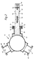
chemical treatment plant 10 including areactor tank 12 provided with a heating and/orcooling jacket 13,internal baffles 14, astirrer 15 driven by amotor 16,inlets outlet 19 for a product. Aloop 20 communicates between twoports tank 12, and incorporates apump 24 so liquids from thetank 12 may be circulated through theloop 20. A sonochemical apparatus 25 (shown diagrammatically) forms part of theloop 20, and can be isolated byvalves 26. Theapparatus 25 includes acollar 28 filled with olive oil; the oil is circulated by apump 27 through aheat exchanger 29 during operation, the circuit including anexpansion tank 30 covered by aflexible membrane 31 to ensure the oil does not become contaminated for example by water vapour. - It will be understood that the liquid being passed through the
sonochemical apparatus 25 might be a single phase for example a mixture of water-soluble reactants in water, or might be more than one phase, for example a mixture of two or more immiscible liquids, or particulate matter in suspension. It will also be appreciated that theplant 10 might incorporate more than oneloop 20 connected to thetank 12, so the flows of liquid in theloops 20 are in parallel; also, within any oneloop 20 there might be more than onesonochemical apparatus 25 through which the liquid would flow in series. - Referring now to Figure 2 there is shown a cross-sectional view of a
sonochemical apparatus 25 suitable for use in theloop 20 of Figure 1. Theapparatus 25 includes a length ofstainless steel tube 35 of wall thickness 2.5 mm and bore diameter 125 mm, with a flange 36 (shown in Figure 3) at each end so it can be connected into theloop 20. Three steppedstainless steel collars 38 of wall thickness 3 mm are welded to the outside of thetube 35 in a common plane, equally spaced around it; at the outer end of each is amounting flange 40. Referring also to Figure 3, eachcollar 38 is provided withinlet ports 42 andoutlet ports 44 for circulatingolive oil 43 through thecollar 38 and aheat exchanger 29 as described above in relation to Figure 1. Eachcollar 38 encloses one end of a generally cylindrical titanium alloy half-wavelength coupler 46 (only one being shown in Figure 2) which has anodal flange 48. Thecoupler 46 is held coaxial with thecollar 38 with its end face 6 mm from the outside of the wall of thetube 35 by clamping the outer edge of thenodal flange 48 between twosilicone rubber gaskets 50 held between themounting flange 40 and asteel clamping ring 52 and secured by screws 54 (only two are shown). - To the other end of the
coupler 46 is firmly fixed atransducer assembly 56 by means of a short threadedstud 58 which engages in correspondingly threaded holes in thecoupler 46 and theassembly 56. The abutting faces are smooth and flat to maximize the coupling of ultrasonic waves from theassembly 56 into thecoupler 46. The resonant frequency of theassembly 56 is 20 kHz, and thecoupler 46 is half a wavelength long at that frequency, so that theflange 48 is at a position which in operation is a node of displacement. The end of thecoupler 46 adjacent to theassembly 56 is 33 mm in diameter (the same diameter as the adjacent end of the assembly 56), but the other end is ofdiameter 50 mm in order to couple ultrasound more efficiently into theolive oil 43. At each end is a short cylindrical portion; between the wider end portion and theflange 48 thecoupler 46 tapers uniformly; thecoupler 46 has the same diameter at each side of theflange 48 and on each side of theflange 48 is a fillet; and between theflange 48 and the narrower end portion is a cylindrical portion and then a short tapered portion. - The
transducer assembly 56 comprises a generally cylindrical titanium alloy coupling block 60 (which also defines a nodal flange 62) and a cylindrical titaniumalloy backing block 64, between which are sandwiched twoannular discs 66 of pzt (lead zirconate titanate) piezo-electric material polarized in opposite directions. Theassembly 56 is held together by an8mm diameter bolt 68 which is tight enough to ensure thediscs 66 remain in compression in operation. The dimensions and masses are such that theassembly 56 resonates at about 20 kHz. Such an assembly is available from Sonic Systems, Isle Brewers, Taunton, Somerset. - In operation of the
apparatus 25 eachtransducer assembly 56 is connected to a respective 20 kHz signal generator (not shown), the electrical signals being supplied to the adjacent faces of thediscs 66 and the outer faces being earthed. Typically each generator might provide an electrical power of about 250 W to theassembly 56.Olive oil 43 is circulated through thecollars 38 and theheat exchanger 29 to prevent overheating. Due to energy losses, principally due to reflection at the interface between theolive oil 43 and thetube 35, the sonic power to which the liquid inside thetube 35 is subjected is about 100 W from eachassembly 56. Where the liquid is water, cavitation has been found to occur over a length of thetube 35 of about 300 mm, so the treated volume is about 3.6 litres.
Claims (12)
- An apparatus for subjecting a liquid to a high ultrasonic intensity comprising means (35) defining a chamber for the liquid, and a transducer assembly (56) adapted when energised to generate ultrasonic waves at an operating frequency, characterised by at least one collar (38) fixed to the outside of a wall (35) of the chamber, each collar (38) enclosing part of an ultrasonic coupler (46) adapted to resonate at the operating frequency and having a nodal flange (48) by which it is fixed to the end of the collar (38) remote from the wall (35) such that there is a gap between the sides of the coupler (46) and the collar (38), and a gap between the end of the coupler (46) and the wall (35), and a low attenuation buffer liquid with a cavitation threshold above that of the liquid in the chamber filling the collar (38) and so occupying the gaps between the coupler (46) and both the collar (38) and the wall (35), the transducer assembly (56) being fixed to the end of the coupler (46) outside the collar (38) and adapted when energised to generate ultrasonic waves of the operating frequency in the coupler (46).
- Apparatus as claimed in Claim 1 wherein the coupler (46) is half a wavelength long at the operating frequency, and is tapered along at least part of its length.
- Apparatus as claimed in Claim 1 or Claim 2 wherein there is no change in the diameter of the coupler (46) between opposite sides of the nodal flange (48).
- Apparatus as claimed in any one of Claims 1 to 3 wherein the wall (35) adjacent to the end of the coupler (46) comprises steel, and is of thickness less than 5 mm.
- Apparatus as claimed in Claim 4 wherein the said wall is 2.5 mm thick.
- Apparatus as claimed in any one of the preceding Claims wherein the collar (38) is of such a length that the gap between the end of the coupler (46) and the nearest part of the wall (35) is less than 10 mm and is much less than a quarter wavelength in the buffer liquid at the operating frequency.
- Apparatus as claimed in any one of the preceding Claims wherein the collar (38) is of such a diameter that the gap between the sides of the coupler (46) and the collar (38) is between 2 mm and 10 mm.
- Apparatus as claimed in any one of the preceding Claims wherein the collar (38) itself is of thickness between 2 mm and 5 mm.
- Apparatus as claimed in any one of the preceding Claims also including means (27) to circulate the buffer liquid and means (29) to cool it.
- Apparatus as claimed in any one of the preceding Claims wherein the means defining a chamber for the liquid comprises a cylindrical tube (35), the apparatus also comprising means (24) to cause the liquid to flow through the tube (35).
- Apparatus as claimed in any one of the preceding Claims wherein the wall (35) of the chamber to which the collar (38) is fixed is integral with the means (35) defining the chamber.
- Apparatus as claimed in Claim 10 wherein there are three collars (38), each with a respective coupler (46) and transducer asembly (56), fixed to the outside of the tube (35) and equally spaced around it, lying in a common plane.
Applications Claiming Priority (2)
| Application Number | Priority Date | Filing Date | Title |
|---|---|---|---|
| GB909006989A GB9006989D0 (en) | 1990-03-28 | 1990-03-28 | Sonochemical apparatus |
| GB9006989 | 1990-03-28 |
Publications (3)
| Publication Number | Publication Date |
|---|---|
| EP0449008A2 EP0449008A2 (en) | 1991-10-02 |
| EP0449008A3 EP0449008A3 (en) | 1991-12-11 |
| EP0449008B1 true EP0449008B1 (en) | 1994-07-20 |
Family
ID=10673444
Family Applications (1)
| Application Number | Title | Priority Date | Filing Date |
|---|---|---|---|
| EP91103527A Expired - Lifetime EP0449008B1 (en) | 1990-03-28 | 1991-03-08 | Sonochemical apparatus |
Country Status (5)
| Country | Link |
|---|---|
| US (1) | US5658534A (en) |
| EP (1) | EP0449008B1 (en) |
| DE (1) | DE69102918T2 (en) |
| ES (1) | ES2056510T3 (en) |
| GB (2) | GB9006989D0 (en) |
Families Citing this family (78)
| Publication number | Priority date | Publication date | Assignee | Title |
|---|---|---|---|---|
| DK102592A (en) * | 1992-08-18 | 1994-02-19 | Reson System As | Cavitation membrane transducer |
| DE4228618A1 (en) * | 1992-08-28 | 1994-03-03 | Hoechst Ag | Reactor for carrying out chemical reactions |
| GB2276567B (en) * | 1993-04-03 | 1996-11-27 | Atomic Energy Authority Uk | Processing vessel |
| GB9307225D0 (en) * | 1993-04-03 | 1993-05-26 | Atomic Energy Authority Uk | Processing vessel |
| US5529753A (en) * | 1993-07-09 | 1996-06-25 | Dade International Inc. | System for ultrasonic energy coupling by irrigation |
| US5395592A (en) * | 1993-10-04 | 1995-03-07 | Bolleman; Brent | Acoustic liquid processing device |
| DE4444005A1 (en) * | 1994-12-10 | 1996-06-20 | Stn Atlas Elektronik Gmbh | Electroacoustic transducer in flextensional technology |
| GB9708449D0 (en) * | 1997-04-26 | 1997-06-18 | British Nuclear Fuels Plc | Acoustic apparatus and method |
| GB9708451D0 (en) * | 1997-04-26 | 1997-06-18 | British Nuclear Fuels Plc | An acoustic apparatus |
| US6465015B1 (en) | 1998-02-24 | 2002-10-15 | Arch Chemicals, Inc. | Sonic method of enhancing chemical reactions to provide uniform, non-agglomerated particles |
| CA2238951A1 (en) | 1998-05-26 | 1999-11-26 | Les Technologies Sonomax Inc. | Acoustic cavitation reactor for the processing of materials |
| US7354556B2 (en) * | 1998-12-12 | 2008-04-08 | Accentus Plc | Process and apparatus for irradiating fluids |
| GB9827360D0 (en) * | 1998-12-12 | 1999-02-03 | Aea Technology Plc | Process and apparatus for irradiating fluids |
| US6682724B2 (en) | 1999-02-23 | 2004-01-27 | Arch Chemcials, Inc. | Sonic method of enhancing chemical reactions to provide uniform, non-agglomerated particles |
| US8096700B2 (en) * | 1999-11-24 | 2012-01-17 | Impulse Devices Inc. | Heat exchange system for a cavitation chamber |
| US7387660B2 (en) * | 1999-11-24 | 2008-06-17 | Impulse Devices, Inc., | Degassing procedure for a cavitation chamber |
| US7381241B2 (en) * | 1999-11-24 | 2008-06-03 | Impulse Devices, Inc. | Degassing procedure for a cavitation chamber |
| US7448790B2 (en) * | 1999-11-24 | 2008-11-11 | Impulse Devices, Inc. | Cavitation fluid circulatory system for a cavitation chamber |
| WO2001039204A2 (en) * | 1999-11-24 | 2001-05-31 | Impulse Devices, Inc. | Shaped core cavitation nuclear reactor |
| US7467945B2 (en) * | 2004-09-10 | 2008-12-23 | S.C. Johnson & Son, Inc. | Candle assembly and fuel element therefor |
| FR2803292B1 (en) * | 1999-12-30 | 2002-02-15 | Rhodia Polyamide Intermediates | PROCESS FOR THE MANUFACTURE OF DIAMINE SALT AND CARBOXYLIC DIACIDE |
| US6489707B1 (en) | 2000-01-28 | 2002-12-03 | Westinghouse Savannah River Company | Method and apparatus for generating acoustic energy |
| GB0004941D0 (en) * | 2000-03-02 | 2000-04-19 | Aea Technology Plc | Ultrasonic transducer coupling |
| FR2825294B1 (en) * | 2001-05-29 | 2004-05-21 | Commissariat Energie Atomique | METHOD AND DEVICE FOR SELECTIVELY ELIMINATING FUNCTIONALIZED ORGANIC COMPOUNDS FROM A LIQUID MEDIUM |
| IL144638A (en) * | 2001-07-30 | 2005-12-18 | Nano Size Ltd | High power ultrasound reactor for the production of nano-powder materials |
| DE10137017A1 (en) | 2001-07-30 | 2003-02-20 | Basf Ag | Crystallization process for the adjustment of small particles |
| US6634539B2 (en) | 2001-09-21 | 2003-10-21 | 3M Innovative Properties Company | Adjustable-gap rotary ultrasonic horn mounting apparatus and method for mounting |
| US7243894B2 (en) | 2002-02-15 | 2007-07-17 | 3M Innovative Properties Company | Mount for vibratory elements |
| US6916418B2 (en) * | 2002-03-13 | 2005-07-12 | Harris Acoustic Products Corporation | Assembly and method for purifying water at a point of use and apparatus and method for testing same |
| US20050008739A1 (en) * | 2002-03-13 | 2005-01-13 | Harris Acoustic Products Corp. | Method and assembly for pasteurizing and homogenizing low viscosity liquids |
| US20050288541A1 (en) * | 2002-03-19 | 2005-12-29 | Sherwood Steven P | Gas to liquid conversion process |
| US20030233019A1 (en) * | 2002-03-19 | 2003-12-18 | Sherwood Steven P. | Gas to liquid conversion process |
| IL149932A0 (en) * | 2002-05-30 | 2002-11-10 | Nano Size Ltd | High power ultrasonic reactor and process for ultrasonic treatment of a reaction material |
| US6786384B1 (en) * | 2003-06-13 | 2004-09-07 | 3M Innovative Properties Company | Ultrasonic horn mount |
| US20040259100A1 (en) | 2003-06-20 | 2004-12-23 | Illumina, Inc. | Methods and compositions for whole genome amplification and genotyping |
| US20070035208A1 (en) * | 2004-09-01 | 2007-02-15 | Impulse Devices Inc. | Acoustic driver assembly with restricted contact area |
| US7218033B2 (en) * | 2004-09-01 | 2007-05-15 | Impulse Devices, Inc. | Acoustic driver assembly with restricted contact area |
| US20060043838A1 (en) * | 2004-09-01 | 2006-03-02 | Impulse Devices, Inc. | Acoustic driver assembly with restricted contact area |
| US7425791B2 (en) * | 2004-09-01 | 2008-09-16 | Impulse Devices, Inc. | Acoustic driver assembly with recessed head mass contact surface |
| US7425792B2 (en) * | 2004-09-01 | 2008-09-16 | Impulse Devices, Inc. | Acoustic driver assembly with restricted contact area |
| US7122943B2 (en) * | 2004-09-01 | 2006-10-17 | Impulse Devices, Inc. | Acoustic driver assembly with restricted contact area |
| US7218034B2 (en) * | 2004-09-01 | 2007-05-15 | Impulse Devices, Inc. | Acoustic driver assembly with restricted contact area |
| US7126256B2 (en) * | 2004-09-01 | 2006-10-24 | Impulse Devices, Inc. | Acoustic driver assembly with recessed head mass contact surface |
| US20060043835A1 (en) * | 2004-09-01 | 2006-03-02 | Impulse Devices Inc. | Acoustic driver assembly with restricted contact area |
| US20060043840A1 (en) * | 2004-09-01 | 2006-03-02 | Impulse Devices Inc. | Acoustic driver assembly with restricted contact area |
| US7224103B2 (en) | 2004-09-01 | 2007-05-29 | Impulse Devices, Inc. | Acoustic driver assembly with recessed head mass contact surface |
| US6958569B1 (en) | 2004-09-01 | 2005-10-25 | Impulse Devices, Inc. | Acoustic driver assembly for a spherical cavitation chamber |
| US7122941B2 (en) * | 2004-09-01 | 2006-10-17 | Impulse Devices, Inc. | Acoustic driver assembly with recessed head mass contact surface |
| US7126258B2 (en) * | 2004-09-01 | 2006-10-24 | Impulse Devices, Inc. | Acoustic driver assembly with recessed head mass contact surface |
| US7380974B2 (en) * | 2005-01-18 | 2008-06-03 | Impulse Devices, Inc. | Hydraulic actuated cavitation chamber with integrated fluid rotation system |
| US7380975B2 (en) * | 2005-01-18 | 2008-06-03 | Impulse Devices, Inc. | Hydraulic actuated cavitation chamber with integrated fluid rotation system |
| US7448791B2 (en) * | 2005-01-18 | 2008-11-11 | Impulse Devices, Inc. | Hydraulic actuated cavitation chamber with integrated fluid rotation system |
| US7425091B2 (en) * | 2005-01-18 | 2008-09-16 | Impulse Devices, Inc. | Hydraulic actuated cavitation chamber with integrated fluid rotation system |
| US7425092B1 (en) * | 2005-01-18 | 2008-09-16 | Impulse Devices, Inc. | Hydraulic actuated cavitation chamber with integrated fluid rotation system |
| US7448792B2 (en) * | 2005-01-18 | 2008-11-11 | Impulse Devices, Inc. | Hydraulic actuated cavitation chamber with integrated fluid rotation system |
| US7510321B2 (en) * | 2005-02-28 | 2009-03-31 | Impulse Devices, Inc. | Hydraulic actuated cavitation chamber |
| US20060159560A1 (en) * | 2005-01-18 | 2006-07-20 | Impulse Devices, Inc. | Hydraulic actuated cavitation chamber with integrated fluid rotation system |
| GB0503193D0 (en) * | 2005-02-16 | 2005-03-23 | Accentus Plc | Ultrasonic treatment plant |
| US20060269458A1 (en) * | 2005-05-27 | 2006-11-30 | Impulse Devices, Inc. | Hourglass-shaped cavitation chamber with spherical lobes |
| US20060269460A1 (en) * | 2005-05-27 | 2006-11-30 | Impulse Devices, Inc. | Hourglass-shaped cavitation chamber with spherical lobes |
| US8187545B2 (en) * | 2005-05-27 | 2012-05-29 | Impulse Devices Inc. | Hourglass-shaped cavitation chamber with spherical lobes |
| US20060269456A1 (en) * | 2005-05-27 | 2006-11-30 | Impulse Devices, Inc. | Hourglass-shaped cavitation chamber |
| US20060269459A1 (en) * | 2005-05-27 | 2006-11-30 | Impulse Devices, Inc. | Hourglass-shaped cavitation chamber with spherical lobes |
| US20070103034A1 (en) * | 2005-11-04 | 2007-05-10 | Impulse Devices Inc. | Acoustic driver assembly with increased head mass displacement amplitude |
| US20070138911A1 (en) * | 2005-12-16 | 2007-06-21 | Impulse Devices Inc. | Tunable acoustic driver and cavitation chamber assembly |
| US7461965B2 (en) * | 2005-12-16 | 2008-12-09 | Impulse Devices, Inc. | Cavitation chamber with flexibly mounted reflector |
| US7510322B2 (en) * | 2005-12-16 | 2009-03-31 | Impulse Devices, Inc. | High pressure cavitation chamber with dual internal reflectors |
| EP1993513A4 (en) * | 2006-03-14 | 2012-06-27 | Merck Sharp & Dohme | Processes and apparatuses for the production of crystalline organic microparticle compositions by micro-milling and crystallization on micro-seed and their use |
| US7846341B2 (en) | 2006-12-04 | 2010-12-07 | Bacoustics, Llc | Method of ultrasonically treating a continuous flow of fluid |
| US7767159B2 (en) * | 2007-03-29 | 2010-08-03 | Victor Nikolaevich Glotov | Continuous flow sonic reactor and method |
| US7787330B1 (en) * | 2007-10-03 | 2010-08-31 | Karl Reid | Removable protective device for a submersible liquid transmitter |
| ES2327308B1 (en) * | 2007-12-26 | 2010-07-26 | Instituto Andaluz De Investigacion Y Formacion Agraria, Pesquera, Alimentaria Y De La Produccion E. | APPARATUS AND PROCEDURE FOR CONTINUOUS AND UNIFORM HEATING OF MASSED OLIVE MASS BY ULTRASOUNDS. |
| US8370996B2 (en) * | 2009-06-09 | 2013-02-12 | Impulse Devices Inc. | Acoustical treatment of polymeric fibers and small particles and apparatus therefor |
| US8026496B2 (en) | 2009-07-02 | 2011-09-27 | Raytheon Company | Acoustic crystal sonoluminescent cavitation devices and IR/THz sources |
| US20120216876A1 (en) * | 2010-11-16 | 2012-08-30 | Impulse Devices Inc. | Suppression and Separation of Interactive Acoustic Modes in a Fluid-Filled Resonator |
| ES2532552B1 (en) * | 2013-09-27 | 2016-01-12 | Biosonoil, S.L. | Procedure and device for obtaining hydrocarbons |
| ES2478190B2 (en) * | 2014-03-13 | 2015-01-28 | Productos Agrovin, S.A. | Application of ultrasound in winemaking processes |
| WO2018098097A1 (en) | 2016-11-22 | 2018-05-31 | Khalifa University of Science and Technology | Continuous sono-chemical reactors and methods of using the same |
Family Cites Families (13)
| Publication number | Priority date | Publication date | Assignee | Title |
|---|---|---|---|---|
| US3113287A (en) * | 1956-03-29 | 1963-12-03 | Raytheon Co | Electroacoustical transducer mounted on boat hull |
| US3800275A (en) * | 1960-09-02 | 1974-03-26 | Us Navy | Acoustic image conversion tube |
| US3331589A (en) * | 1965-02-08 | 1967-07-18 | Frederick G Hammitt | Vibratory unit with seal |
| US3587669A (en) * | 1966-02-05 | 1971-06-28 | Topsoe Haldor F A | Process for providing reactors with catalysts and vibrator for use in carrying out the process |
| US3525606A (en) * | 1968-01-16 | 1970-08-25 | Albert G Bodine | Vibrational method for penetrating,leaching and extracting minerals |
| US3771117A (en) * | 1972-03-01 | 1973-11-06 | Westinghouse Electric Corp | Transducer installation |
| US4074152A (en) * | 1974-09-30 | 1978-02-14 | Kabushiki Kaisha Toyota Chuo Kenkyusho | Ultrasonic wave generator |
| US4001765A (en) * | 1975-03-31 | 1977-01-04 | Marine Resources, Inc. | Pressure compensating sound transducer apparatus |
| US4369100A (en) * | 1977-09-27 | 1983-01-18 | Sawyer Harold T | Method for enhancing chemical reactions |
| US4433916A (en) * | 1982-11-02 | 1984-02-28 | Hall Mark N | Acoustic resonator having transducer pairs excited with phase-displaced energy |
| JPS60233997A (en) * | 1984-05-04 | 1985-11-20 | Ngk Spark Plug Co Ltd | Submerged echo sounder transducer |
| US4821838A (en) * | 1987-10-30 | 1989-04-18 | Hewlett-Packard Company | Acoustic damper |
| DE3816567A1 (en) * | 1988-05-14 | 1989-11-16 | Walter Martin Ultraschalltech | ULTRASONIC DEVICE |
-
1990
- 1990-03-28 GB GB909006989A patent/GB9006989D0/en active Pending
-
1991
- 1991-03-08 ES ES91103527T patent/ES2056510T3/en not_active Expired - Lifetime
- 1991-03-08 DE DE69102918T patent/DE69102918T2/en not_active Expired - Fee Related
- 1991-03-08 EP EP91103527A patent/EP0449008B1/en not_active Expired - Lifetime
- 1991-03-20 GB GB9105879A patent/GB2243092B/en not_active Expired - Fee Related
-
1993
- 1993-12-21 US US08/170,630 patent/US5658534A/en not_active Expired - Fee Related
Also Published As
| Publication number | Publication date |
|---|---|
| GB9105879D0 (en) | 1991-05-08 |
| EP0449008A2 (en) | 1991-10-02 |
| DE69102918D1 (en) | 1994-08-25 |
| ES2056510T3 (en) | 1994-10-01 |
| GB2243092B (en) | 1993-10-13 |
| GB9006989D0 (en) | 1990-05-23 |
| EP0449008A3 (en) | 1991-12-11 |
| GB2243092A (en) | 1991-10-23 |
| DE69102918T2 (en) | 1995-02-02 |
| US5658534A (en) | 1997-08-19 |
Similar Documents
| Publication | Publication Date | Title |
|---|---|---|
| EP0449008B1 (en) | Sonochemical apparatus | |
| US5026167A (en) | Ultrasonic fluid processing system | |
| US6361747B1 (en) | Reactor with acoustic cavitation | |
| JP3483928B2 (en) | Processing container | |
| US5032027A (en) | Ultrasonic fluid processing method | |
| US4118797A (en) | Ultrasonic emulsifier and method | |
| US7504075B2 (en) | Ultrasonic reactor and process for ultrasonic treatment of materials | |
| Mason | Industrial sonochemistry: potential and practicality | |
| US5395592A (en) | Acoustic liquid processing device | |
| EP0648531B1 (en) | Fluid processing | |
| AU8391582A (en) | Acoustic degasification of pressurized liquids | |
| EP1148943B1 (en) | Process and apparatus for irradiating fluids | |
| US7354556B2 (en) | Process and apparatus for irradiating fluids | |
| GB2276567A (en) | Processing vessel with ultrasonics | |
| EP2195122A2 (en) | High capacity ultrasonic reactor system | |
| US20060050605A1 (en) | High-power sono-chemical reactor | |
| US6733727B1 (en) | Condensation induced water hammer driven sterilization | |
| RU2222387C1 (en) | Piezoelectric through-type ultrasonic converter | |
| US20200122102A1 (en) | Ultrasonic cavitation method and mixer for oil-based botanical extracts | |
| JP3252971B2 (en) | Sonochemical equipment | |
| Gallego Juárez | Macrosonics: Phenomena, transducers and applications | |
| RU2221633C2 (en) | Ultrasonic flow-type disperser | |
| EP4190440A1 (en) | Intensified multifrequency sonoreactor device | |
| WO2006130237A1 (en) | Hourglass-shaped cavitation chamber | |
| SU1766798A1 (en) | Fluid transportation device |
Legal Events
| Date | Code | Title | Description |
|---|---|---|---|
| PUAI | Public reference made under article 153(3) epc to a published international application that has entered the european phase |
Free format text: ORIGINAL CODE: 0009012 |
|
| AK | Designated contracting states |
Kind code of ref document: A2 Designated state(s): BE CH DE ES FR IT LI NL SE |
|
| PUAL | Search report despatched |
Free format text: ORIGINAL CODE: 0009013 |
|
| AK | Designated contracting states |
Kind code of ref document: A3 Designated state(s): BE CH DE ES FR IT LI NL SE |
|
| 17P | Request for examination filed |
Effective date: 19920203 |
|
| RAP1 | Party data changed (applicant data changed or rights of an application transferred) |
Owner name: UNITED KINGDOM ATOMIC ENERGY AUTHORITY |
|
| 17Q | First examination report despatched |
Effective date: 19931115 |
|
| GRAA | (expected) grant |
Free format text: ORIGINAL CODE: 0009210 |
|
| AK | Designated contracting states |
Kind code of ref document: B1 Designated state(s): BE CH DE ES FR IT LI NL SE |
|
| ITF | It: translation for a ep patent filed |
Owner name: JACOBACCI CASETTA & PERANI S.P.A. |
|
| ET | Fr: translation filed | ||
| REF | Corresponds to: |
Ref document number: 69102918 Country of ref document: DE Date of ref document: 19940825 |
|
| REG | Reference to a national code |
Ref country code: ES Ref legal event code: FG2A Ref document number: 2056510 Country of ref document: ES Kind code of ref document: T3 |
|
| EAL | Se: european patent in force in sweden |
Ref document number: 91103527.7 |
|
| PLBE | No opposition filed within time limit |
Free format text: ORIGINAL CODE: 0009261 |
|
| STAA | Information on the status of an ep patent application or granted ep patent |
Free format text: STATUS: NO OPPOSITION FILED WITHIN TIME LIMIT |
|
| 26N | No opposition filed | ||
| ITTA | It: last paid annual fee | ||
| REG | Reference to a national code |
Ref country code: CH Ref legal event code: PUE Owner name: UNITED KINGDOM ATOMIC ENERGY AUTHORITY TRANSFER- A |
|
| REG | Reference to a national code |
Ref country code: ES Ref legal event code: PC2A |
|
| REG | Reference to a national code |
Ref country code: FR Ref legal event code: TP |
|
| NLS | Nl: assignments of ep-patents |
Owner name: AEA TECHNOLOGY PLC |
|
| REG | Reference to a national code |
Ref country code: CH Ref legal event code: PUE Owner name: AEA TECHNOLOGY PLC TRANSFER- ACCENTUS PLC |
|
| NLS | Nl: assignments of ep-patents |
Owner name: ACCENTUS PLC |
|
| REG | Reference to a national code |
Ref country code: CH Ref legal event code: PFA Owner name: ACCENTUS PLC Free format text: ACCENTUS PLC#329 HARWELL#DIDCOT, OXFORDSHIRE OX11OQJ (GB) -TRANSFER TO- ACCENTUS PLC#3RD FLOOR 11 STRAND#LONDON WC2N 5HR (GB) |
|
| REG | Reference to a national code |
Ref country code: FR Ref legal event code: CA |
|
| REG | Reference to a national code |
Ref country code: CH Ref legal event code: PFA Owner name: ACCENTUS PLC Free format text: ACCENTUS PLC#3RD FLOOR 11 STRAND#LONDON WC2N 5HR (GB) -TRANSFER TO- ACCENTUS PLC#3RD FLOOR 11 STRAND#LONDON WC2N 5HR (GB) |
|
| PGFP | Annual fee paid to national office [announced via postgrant information from national office to epo] |
Ref country code: CH Payment date: 20080218 Year of fee payment: 18 Ref country code: ES Payment date: 20080325 Year of fee payment: 18 |
|
| PGFP | Annual fee paid to national office [announced via postgrant information from national office to epo] |
Ref country code: IT Payment date: 20080218 Year of fee payment: 18 Ref country code: SE Payment date: 20080218 Year of fee payment: 18 Ref country code: NL Payment date: 20080214 Year of fee payment: 18 |
|
| PGFP | Annual fee paid to national office [announced via postgrant information from national office to epo] |
Ref country code: DE Payment date: 20080227 Year of fee payment: 18 Ref country code: FR Payment date: 20080211 Year of fee payment: 18 |
|
| PGFP | Annual fee paid to national office [announced via postgrant information from national office to epo] |
Ref country code: BE Payment date: 20080313 Year of fee payment: 18 |
|
| BERE | Be: lapsed |
Owner name: *ACCENTUS P.L.C. Effective date: 20090331 |
|
| REG | Reference to a national code |
Ref country code: CH Ref legal event code: PL |
|
| EUG | Se: european patent has lapsed | ||
| NLV4 | Nl: lapsed or anulled due to non-payment of the annual fee |
Effective date: 20091001 |
|
| REG | Reference to a national code |
Ref country code: FR Ref legal event code: ST Effective date: 20091130 |
|
| PG25 | Lapsed in a contracting state [announced via postgrant information from national office to epo] |
Ref country code: CH Free format text: LAPSE BECAUSE OF NON-PAYMENT OF DUE FEES Effective date: 20090331 Ref country code: DE Free format text: LAPSE BECAUSE OF NON-PAYMENT OF DUE FEES Effective date: 20091001 Ref country code: LI Free format text: LAPSE BECAUSE OF NON-PAYMENT OF DUE FEES Effective date: 20090331 |
|
| PG25 | Lapsed in a contracting state [announced via postgrant information from national office to epo] |
Ref country code: BE Free format text: LAPSE BECAUSE OF NON-PAYMENT OF DUE FEES Effective date: 20090331 Ref country code: NL Free format text: LAPSE BECAUSE OF NON-PAYMENT OF DUE FEES Effective date: 20091001 |
|
| PG25 | Lapsed in a contracting state [announced via postgrant information from national office to epo] |
Ref country code: FR Free format text: LAPSE BECAUSE OF NON-PAYMENT OF DUE FEES Effective date: 20091123 |
|
| REG | Reference to a national code |
Ref country code: ES Ref legal event code: FD2A Effective date: 20090309 |
|
| PG25 | Lapsed in a contracting state [announced via postgrant information from national office to epo] |
Ref country code: ES Free format text: LAPSE BECAUSE OF NON-PAYMENT OF DUE FEES Effective date: 20090309 |
|
| PG25 | Lapsed in a contracting state [announced via postgrant information from national office to epo] |
Ref country code: IT Free format text: LAPSE BECAUSE OF NON-PAYMENT OF DUE FEES Effective date: 20090308 |
|
| PG25 | Lapsed in a contracting state [announced via postgrant information from national office to epo] |
Ref country code: SE Free format text: LAPSE BECAUSE OF NON-PAYMENT OF DUE FEES Effective date: 20090309 |