EP0448945A2 - A method and apparatus for barcode recognition in a digital image - Google Patents
A method and apparatus for barcode recognition in a digital image Download PDFInfo
- Publication number
- EP0448945A2 EP0448945A2 EP91102002A EP91102002A EP0448945A2 EP 0448945 A2 EP0448945 A2 EP 0448945A2 EP 91102002 A EP91102002 A EP 91102002A EP 91102002 A EP91102002 A EP 91102002A EP 0448945 A2 EP0448945 A2 EP 0448945A2
- Authority
- EP
- European Patent Office
- Prior art keywords
- barcode
- black
- array
- run
- digital image
- Prior art date
- Legal status (The legal status is an assumption and is not a legal conclusion. Google has not performed a legal analysis and makes no representation as to the accuracy of the status listed.)
- Withdrawn
Links
Images


Classifications
-
- G—PHYSICS
- G06—COMPUTING OR CALCULATING; COUNTING
- G06K—GRAPHICAL DATA READING; PRESENTATION OF DATA; RECORD CARRIERS; HANDLING RECORD CARRIERS
- G06K7/00—Methods or arrangements for sensing record carriers, e.g. for reading patterns
- G06K7/10—Methods or arrangements for sensing record carriers, e.g. for reading patterns by electromagnetic radiation, e.g. optical sensing; by corpuscular radiation
- G06K7/10544—Methods or arrangements for sensing record carriers, e.g. for reading patterns by electromagnetic radiation, e.g. optical sensing; by corpuscular radiation by scanning of the records by radiation in the optical part of the electromagnetic spectrum
- G06K7/10821—Methods or arrangements for sensing record carriers, e.g. for reading patterns by electromagnetic radiation, e.g. optical sensing; by corpuscular radiation by scanning of the records by radiation in the optical part of the electromagnetic spectrum further details of bar or optical code scanning devices
- G06K7/1093—Methods or arrangements for sensing record carriers, e.g. for reading patterns by electromagnetic radiation, e.g. optical sensing; by corpuscular radiation by scanning of the records by radiation in the optical part of the electromagnetic spectrum further details of bar or optical code scanning devices sensing, after transfer of the image of the data-field to an intermediate store, e.g. storage with cathode ray tube
-
- G—PHYSICS
- G06—COMPUTING OR CALCULATING; COUNTING
- G06K—GRAPHICAL DATA READING; PRESENTATION OF DATA; RECORD CARRIERS; HANDLING RECORD CARRIERS
- G06K7/00—Methods or arrangements for sensing record carriers, e.g. for reading patterns
- G06K7/10—Methods or arrangements for sensing record carriers, e.g. for reading patterns by electromagnetic radiation, e.g. optical sensing; by corpuscular radiation
- G06K7/14—Methods or arrangements for sensing record carriers, e.g. for reading patterns by electromagnetic radiation, e.g. optical sensing; by corpuscular radiation using light without selection of wavelength, e.g. sensing reflected white light
Definitions
- the invention disclosed broadly relates to data processing systems and more particularly relates to improvements in barcode recognition.
- Modern digital scanning machinery can scan a page of paper in less than one second. If a human operator then has to view the image representation and key enter the relevant code information, the effective capture speed takes, perhaps, 15-20 seconds. This reduces operator productivity and prevents the imaging application from being a cost justified exercise.
- the requirement is to be able to scan the bit patterns in the digital image file and to create coded information for classifying the image.
- OCR optical character recognition
- OMR Optical mark reading
- Barcodes (of which there are probably 15-20 varieties of coding techniques) are now an everyday occurrence on many objects handled by the general public - particularly groceries, toiletries and stationery items. They are easy to generate and print on current art general purpose printers. They are sufficiently unobtrusive on documents that will be scanned into a digital imaging system that they can be an integral part of the page from which coded data needs to be extracted.
- the problem to be solved is to locate the occurrence of a barcode contained in the data representing a digital image and to convert that barcode image into the corresponding coded data.
- the requirement is to get 100% accuracy in recognition - or an indication of failure.
- the digitally scanned image of the page is represented by a bi-level bit string that represents the black and white markings on the page. This bit string is compressed using a standard compression algorithm.
- the invention is a combination of a recognition module and a calling environment which provides information on what type of barcode is to be recognized and the strategy to be applied in identifying and decoding the barcode. For N raster lines of a dimension "x,” an array of one byte sums of dimension "x" is created.
- the sums are the sum of the "1" bits in the rectangular binary image input array in the N lines of the image.
- a threshold value is established to determine the length of each run of either a black or white space. If an element from the sum array is greater than the threshold, then it is assumed to be black. If it is less than a threshold, then it is assumed to be white. Then a new array can be generated which will have a dimension equal to the number of changes from black to white in the original "x-y" digital image. The values in this array will represent the length of each run of same color pels. These runs are then normalized according to rules of a particular barcode standard being handled.
- the barcode is a three out of nine code
- the normalization process for the three out of nine codes starts with a first black run from the array generated in the previous step and it sums the first 10 values. If any individual element value falls outside the environment defined values, then the runs do not represent the image of a valid barcode. If the sum of these 10 values does not fall within the environment defined thresholds, then once again the run does not represent a valid barcode. If the sum passes these tests, it is then divided by a value related to the total number of spatial elements for the barcode being handled.
- the dividend represents the pel width for each spatial element in this occurrence of the barcode.
- Two threshold values are calculated from this dividend, which are used for the normalization process.
- the last part of the normalization process is to create a new array of the same dimension as the array of run lengths. Each element in this array is the dividend of the run length and either the black or the white threshold value.
- the final step in the process involves creating a lookup value in a 16 bit word comprising a representation of M normalized elements, where M is the number of physical elements in each barcode character. The lookup is then matched against a table of valid values for the barcode style.
- the process repeats with the next set of elements. If no valid value is found, the normalization process is restarted at the next black run element in the run array and the process is repeated until a fully valid barcode is found or the image array has been fully processed.
- Fig. 1 shows an example of a three out of nine barcode.
- the data encoded are the three letters "IBM.”
- the asterisk (“*") mark is used as a start/stop character.
- the four vertical lines are respectively separating the "*" from the “I,” the “I” from the “B,” the “B” from the “M,” and the “M” from the “*,” designates the position of the intercharacter spaces.
- the small black square above and to the left of the barcode in Fig. 1 represents other information in the page image.
- Fig. 1 is an example of a good clear image. All the black bars are complete and the white spaces have no black noise introduced.
- Fig. 1 represents the content of an image page which contains a barcode.
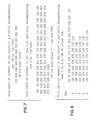
- Fig. 2 shows how, after the scanning operation, the digital image is represented by "rows” and “columns” of pels.
- Six contiguous barcode “rows” are shown, labeled 1-6, plus row -10, which shows image data at an earlier point in the image.
- Two hundred “columns” are taken from column 100 to column 300.
- Fig. 3 shows an example of how the digitized image of Fig. 2 may be "damaged.” In the vertical black bars, some of the "black" area is missing and in the white spaces, black noise is present.
- Fig. 5 shows an expanded view of rows 1-6 and columns 100-141 in Fig. 3.
- Fig. 6 illustrates how the image of Fig. 5 might appear if "skewed.” From column 121, the pels are one row up, corresponding to a five percent skew. From row 4, the pels are one column to the right, corresponding to a 33 percent skew.
- This invention sets out to solve the above problem using software running in an IBM system.
- the initial implementation runs on an Intel x86 processor.
- the technique is applicable to any programmable machine which can handle bit strings, (for example 68000, PC/RT, System/370, AS/400).
- a page has been digitally scanned at a spatial resolution that permits the individual barcode elements (black/white transitions) to be identifiable.
- This typically implies a horizontal resolution (for horizontal oriented barcodes) of at least 200 pels per inch.
- the process described works against the bi-level bit string that represents the image page.
- This bit string is compressed using either the IBM MMR compression algorithm or the CCITT G4 MMR method.
- a description of a suitable bit string compression technique can be found in USP 4,646,356 to Anderson, et al. entitled "Method for Converting a Bit Map of an Image to a Run Length or Run End Representation," assigned to the IBM Corporation and incorporated herein by reference.
- the invention is a combination of a kernel computer program method for barcode recognition and a calling environment which provides information on what type of barcode is to be recognized and the strategy parameters to be used. It also provides the kernel with buffers for the compressed image.
- the example for this description is shown in Fig. 5 as a fragment of the barcode shown in Fig. 3.
- the routine will sum an additional set of rows to those already summed. (In the example a value of 10 rows is used.) This often allows noise to be eliminated. By doing it in two steps, the good quality images can be recognized very quickly and it is only the poor quality ones which need additional processing performed.
- Step 20 obtains one raster line from the compressed image into a run-end array as illustrated in Fig. 7.
- the decompression routine will return a status code if the end of the image page has been processed.
- Step 22 checks this indicator and causes the routine to terminate with a "nothing found” indicator if end of image was detected.
- Step 26 checks the first storage word of the run-end buffer which contains a numeric value related to the number of run-ends detected in this image row. If the number is less than a threshold calculated as being min coded characters * elements per character, then discard this line, as there cannot be valid barcode represented in the image data, and decompress (20) next line. If the number is greater than the threshold, then proceed with 28. In the example, row -10 has only 10 run-ends, so does not meet the minimum requirement of having 4*10 run-ends to represent four coded characters.
- Step 28 now checks that the difference between two run-ends, separated by the threshold number of run-ends, starting with a white run-end (start of black), is between the minimum and maximum thresholds for a valid barcode.
- the difference between run-end 1 and run-end 40 is between 64 and 384, it meets the test. If it does not meet the test, then it is repeated for run-ends 3 and 42 and so on, until the run-end array is exhausted. If the test fails across the whole row, then decompress (20) next line. If the line meets the test, then the line is passed to process B at step 30.
- Step 30 clears the work arrays to zero.
- Step 32 the row passed from Process A is summed to a new array d.
- the array d has a dimension equivalent to the number of pels e in an image row.
- the sum process involves adding 1 to each of the array elements corresponding to black pixels in the image row, e.g. if the 101st pixel is black, then the 101st element will be incremented by one.
- the summing process is performed on a further c-1 rows, which have to be partially decompressed to run-ends, to complete the summing of c rows. This results in an array d whose elements e will have values between 0 (pure white) and c (pure black).
- Steps 34 and 36 process this array d to create a new array f.
- the new array f is calculated where each element is the run length of black or white runs found in the array d.
- the sum run length is the number of contiguous elements which are less than or equal to c/2 (white) or greater than c/2 (black).
- Array f contains a representation of the normalized image after noise and dropout have been considered.
- Step 42 sums the first 10 (number of elements in barcode character) of array f. It checks if sum is between thresholds. If between thresholds, then it continues with 46, else it continues with 44.
- Step 44 increments the pointer into array f to point to next black run length as the "first" for 42. Continue with 42, if not at end of array. If at the end of array, then terminate by returning to Process A.
- Step 46 new array g calculated from array f.
- Elements in g correspond one for one with array f.
- the relationship is calculated by taking the sum from 42, divided by the number of spatial elements in the barcode character.
- thresholds are calculated for white/black wide/narrow elements corresponding to the run lengths in array f.
- the elements in array g then contain the wide/narrow indicators.
- Step 48 combines 10 (depending on barcode type) wide/narrow indicators to a 10 bit value which is used to look up a character code in a table dependent on barcode type. If no valid code found, 50 is executed. If a valid code is found, then 52 is executed.
- Step 50 checks if a valid code has already been found. If so, then the image being processed may be damaged and further processing (summation of additional rows) may help identify a good barcode. If the additional summation has not already been done, c is set to the next sums value provided as a calling option and more rows are processed in 32 and the steps 32-48 repeated.
- Step 54 is entered if a valid barcode character is found. If the image has been skewed down at the left end, a valid character may be found before a start character is decoded. This checks if a start code has been found. If not, the character is not valid in context, so 44 is executed.
- Step 56 is entered if current character is valid and a start character has been decoded. If the code is not a stop character, it is considered as a valid code and control moves to 58. If it is a stop character, control moves to 60.
- step 58 a valid character has been found so it is set to the output buffer and the decoding process is continued with 44.
- Step 60 is entered if start and stop characters, plus some number of data characters have been decoded. A check is made to see if the minimum number specified have been found. If so, then a good barcode has been found and a successful return can be made to the caller. If not, then proceed with 62.
- Step 62 clears the output buffer, as barcode did not meet minimum requirements and continues with step 44.
- This part of the recognition process locates a digital image file and prepares a buffer of compressed bi-level image data for passing to the kernel routine.
- Some applications will know where in the total image page the barcode is likely to be found, so information on the coordinates of that rectangle can be passed to the kernel. This allows the kernel search for potential barcodes to be limited to a range of decompressed rows (need not start looking until the start row is reached and can stop as soon as the maximum vertical extent is reached). Other applications will know only that a barcode appears somewhere within the image. This environment controls the strategy for barcode search. The strategy will depend on, amongst other items -
- the key parameters that are passed to the kernel are:
- the advantages of the invention lie in the applicability of the method to decoding good raster images at a high speed while also being able to adapt itself to handle poor quality, ambiguous images for a slightly longer processing time.
- Discrimination parameters can be set according to the application and what type of barcode and document image the application is directed to.
- the invention is independent of the image scanning resolution, in pels per linear measure, and is independent of barcode geometry, that is the absolute width of the bars.
Landscapes
- Physics & Mathematics (AREA)
- Engineering & Computer Science (AREA)
- Electromagnetism (AREA)
- Health & Medical Sciences (AREA)
- General Health & Medical Sciences (AREA)
- Toxicology (AREA)
- Artificial Intelligence (AREA)
- Computer Vision & Pattern Recognition (AREA)
- General Physics & Mathematics (AREA)
- Theoretical Computer Science (AREA)
- Character Input (AREA)
Abstract
Description
- The invention disclosed broadly relates to data processing systems and more particularly relates to improvements in barcode recognition.
- With digital imaging techniques there is a general requirement to capture coded information that can be associated with the image. This coded information is used to classify the image and to ease later retrieval of the picture from storage.
- Modern digital scanning machinery can scan a page of paper in less than one second. If a human operator then has to view the image representation and key enter the relevant code information, the effective capture speed takes, perhaps, 15-20 seconds. This reduces operator productivity and prevents the imaging application from being a cost justified exercise.
- The requirement is to be able to scan the bit patterns in the digital image file and to create coded information for classifying the image.
- Optical character recognition (OCR) is very sensitive to noise in the image and there is little redundancy in the digital image data representing textual characters to permit (with current art) much higher than a 98% accuracy in recognition - particularly with low resolution digital images such as come from a facsimile machine.
- Optical mark reading (OMR) has been used for some time to allow mechanical classification of images with high reliability. This technique has the disadvantage that the whole image is the OMR data and so the coded data can only be used to classify related images in a set containing the OMR page.
- Barcodes (of which there are probably 15-20 varieties of coding techniques) are now an everyday occurrence on many objects handled by the general public - particularly groceries, toiletries and stationery items. They are easy to generate and print on current art general purpose printers. They are sufficiently unobtrusive on documents that will be scanned into a digital imaging system that they can be an integral part of the page from which coded data needs to be extracted.
- The problem to be solved is to locate the occurrence of a barcode contained in the data representing a digital image and to convert that barcode image into the corresponding coded data. The requirement is to get 100% accuracy in recognition - or an indication of failure. There cannot be partial recognition or potential substitution of characters since the data will be used for classification. (Recognition of "HERE" instead of "THERE" is not acceptable.)
- The requirement is to be able to recognize barcodes where accidental or malicious damage has occurred (for example, someone has written across the paper where the barcode appears). A significant amount of skew that may occur during the image capture process must also be tolerated.
- It is therefore an object of the invention to locate the occurrence of a barcode contained in data representing a digital image, in an improved manner.
- It is another object of the invention to locate the occurrence of a barcode contained in the data representing a digital image and to convert that barcode image into corresponding coded data, in an improved manner.
- It is still a further object of the invention to locate the occurrence of a barcode contained in data representing a digital image and to obtain substantially 100% accuracy in recognition.
- It is still a further object of the invention to locate the occurrence of a barcode contained in data representing a digital image, where the barcode features are obscured.
- It is yet a further object of the invention to locate the occurrence of a barcode contained in data representing a digital image, where there is significant skew of the barcode.
- These and other objects, features and advantages are accomplished by the barcode recognition system and method disclosed herein. A hard copy page which has been digitally scanned at a spatial resolution that permits individual barcode elements to be identifiable, is processed by the invention. The digitally scanned image of the page is represented by a bi-level bit string that represents the black and white markings on the page. This bit string is compressed using a standard compression algorithm. The invention is a combination of a recognition module and a calling environment which provides information on what type of barcode is to be recognized and the strategy to be applied in identifying and decoding the barcode. For N raster lines of a dimension "x," an array of one byte sums of dimension "x" is created. The sums are the sum of the "1" bits in the rectangular binary image input array in the N lines of the image. A threshold value is established to determine the length of each run of either a black or white space. If an element from the sum array is greater than the threshold, then it is assumed to be black. If it is less than a threshold, then it is assumed to be white. Then a new array can be generated which will have a dimension equal to the number of changes from black to white in the original "x-y" digital image. The values in this array will represent the length of each run of same color pels. These runs are then normalized according to rules of a particular barcode standard being handled. For example, if the barcode is a three out of nine code, there are nine elements plus a character separator for each barcoded character. There is also a start character and a stop character which delineates a valid barcode. The normalization process for the three out of nine codes starts with a first black run from the array generated in the previous step and it sums the first 10 values. If any individual element value falls outside the environment defined values, then the runs do not represent the image of a valid barcode. If the sum of these 10 values does not fall within the environment defined thresholds, then once again the run does not represent a valid barcode. If the sum passes these tests, it is then divided by a value related to the total number of spatial elements for the barcode being handled. For example, in a three out of nine barcode, there are 16 spatial elements, seven single width and three triple width elements. The dividend then represents the pel width for each spatial element in this occurrence of the barcode. Two threshold values are calculated from this dividend, which are used for the normalization process. The last part of the normalization process is to create a new array of the same dimension as the array of run lengths. Each element in this array is the dividend of the run length and either the black or the white threshold value. The final step in the process involves creating a lookup value in a 16 bit word comprising a representation of M normalized elements, where M is the number of physical elements in each barcode character. The lookup is then matched against a table of valid values for the barcode style. If a valid value is found, the process repeats with the next set of elements. If no valid value is found, the normalization process is restarted at the next black run element in the run array and the process is repeated until a fully valid barcode is found or the image array has been fully processed.
- These and other objects, features and advantages of the invention will be more fully appreciated with reference to the accompanying figures.
- Fig. 1
- illustrates a perfect barcode, with the barcode elements being perpendicular to the line of the paper.
- Fig. 2
- illustrates how the barcode in Fig. 1 might be represented in a digital image.
- Fig. 3
- illustrates how digital image data of the barcode may be corrupted in practice.
- Fig. 4
- is a table of decoding constraints used to illustrate the invention.
- Fig. 5
- is an expanded view of pels in an obscure barcode.
- Fig. 6
- illustrates how Fig. 5 might appear with a skewed orientation.
- Fig. 7
- depicts a table of numbers which result from partially decompressing a scanned row into run-ends.
- Fig. 8
- is a table of numbers which result from partially decompressing six rows up to a pel column 40.
- Fig. 9
- illustrates how an array of sums of six rows may be built from the table in Fig. 8.
- Fig. 10
- shows how a new array is generated.
- Fig. 11
- illustrates the sum array from the skewed image in Fig. 6.
- Fig. 12
- is a flow diagram of the barcode recognition method, for the initial evaluation of the raster line.
- Fig. 13
- is a flow diagram of a second stage in the recognition of a barcode, continuing from the flow diagram in Fig. 12.
- Fig. 1 shows an example of a three out of nine barcode. The data encoded are the three letters "IBM." The asterisk ("*") mark is used as a start/stop character. The four vertical lines are respectively separating the "*" from the "I," the "I" from the "B," the "B" from the "M," and the "M" from the "*," designates the position of the intercharacter spaces. The small black square above and to the left of the barcode in Fig. 1 represents other information in the page image. Fig. 1 is an example of a good clear image. All the black bars are complete and the white spaces have no black noise introduced. Fig. 1 represents the content of an image page which contains a barcode.
- Fig. 2 shows how, after the scanning operation, the digital image is represented by "rows" and "columns" of pels. Six contiguous barcode "rows" are shown, labeled 1-6, plus row -10, which shows image data at an earlier point in the image. Two hundred "columns" are taken from
column 100 tocolumn 300. - Fig. 3 shows an example of how the digitized image of Fig. 2 may be "damaged." In the vertical black bars, some of the "black" area is missing and in the white spaces, black noise is present. Fig. 5 shows an expanded view of rows 1-6 and columns 100-141 in Fig. 3. Fig. 6 illustrates how the image of Fig. 5 might appear if "skewed." From column 121, the pels are one row up, corresponding to a five percent skew. From
row 4, the pels are one column to the right, corresponding to a 33 percent skew. - This invention sets out to solve the above problem using software running in an IBM system. The initial implementation runs on an Intel x86 processor. The technique is applicable to any programmable machine which can handle bit strings, (for example 68000, PC/RT, System/370, AS/400).
- In the initial image pickup, a page has been digitally scanned at a spatial resolution that permits the individual barcode elements (black/white transitions) to be identifiable. This typically implies a horizontal resolution (for horizontal oriented barcodes) of at least 200 pels per inch. The process described works against the bi-level bit string that represents the image page. This bit string is compressed using either the IBM MMR compression algorithm or the CCITT G4 MMR method. A description of a suitable bit string compression technique can be found in USP 4,646,356 to Anderson, et al. entitled "Method for Converting a Bit Map of an Image to a Run Length or Run End Representation," assigned to the IBM Corporation and incorporated herein by reference.
- The invention is a combination of a kernel computer program method for barcode recognition and a calling environment which provides information on what type of barcode is to be recognized and the strategy parameters to be used. It also provides the kernel with buffers for the compressed image.
- A description of the kernel computer program method and calling environment follows.
- Input -
A pointer to a buffer which contains compressed bi-level image data of dimension "x" pels by "y" pels. The example for this description is shown in Fig. 5 as a fragment of the barcode shown in Fig. 3. - * A series of strategy values, such as shown in the table of Fig. 4.
- Output -
- * A character value
- * A return code indicating success or failure
- Process -
- 1. Partially decompress a raster line of the compressed image to run-ends (Fig. 7 shows a typical result).
- 2. Determine if the line may contain a valid barcode. Fig. 4 shows the values to be used in this example.
- a. There must be at least a defined number of run-ends for this line. With the worked example, for a minimum of four characters in the barcode each with 10 elements, there must be at least 4*10 (40) run-ends in the area under consideration.
- b. The pels encompassed by the above number of run-ends must fall within a range. With the worked example, there must be a minimum of 1*16*4 = 64 pels encompassed by 4*10 run-ends and a maximum of 6*16*4 = 384 pels.
It can be seen that run-end #40 in Fig. 7 meets these requirements so the line is considered for further processing. If this test did not succeed then a return is made to step 1.
The example of Fig. 5 shows just the barcode isolated from the rest of the image page. In practice the barcode will not be at the start of the raster line in the decompressed table, then the line is searched withtest 2 above. This is a very fast check since the table is comprised of pairs of two byte words (white run-end, black run-end) and the difference between the nth and the n+ (40*2)th is the value which must be compared to the thresholds. It is known that the start of a barcode is represented by a white run-end (start of black). At this point a row with a potentially valid barcode is present. - 3. For "n" raster lines of dimension "x" create an array of one byte sums of dimension "x." The sums are the sum of the "1" bits in the rectangular binary image input array in "n" lines of the image. (Fig. 8 shows the fragment run-ends for six lines which are summed as shown in Fig. 9.)
- 4. Using a threshold value derived from the number of lines summed, determine the length of each run of either black or white. If an element from the sum array is greater or equal to the threshold then it is assumed to be black. If less than the threshold it is assumed to be white. A new array is now generated (Fig. 10). This will have a dimension equal to the number of changes from black to white in the original "x" (40) wide digital image. The values in this array will represent the length of each run of same color pels. Fig. 10 shows this.
- 5. These runs are next normalized according to rules specific to a particular barcode standard being handled. For the three out of nine code, there are nine elements plus character separator for each barcoded character. There is also a start character and a stop character which delineate a valid barcode. The normalization process for the three out of nine code starts with the first black run from the array generated in the previous step and sums the first 10 values. If any individual element value falls outside environment defined value (24) then the runs do not represent the image of a valid barcode. If the sum of these 10 does not fall within environment defined thresholds (1*16, 6*16) again the runs do not represented a valid barcode. A sum which passes these tests is then divided by a value related to the total number of spatial elements (not actual elements) for the barcode being handled. (For the three out of nine there are 16 spatial elements - seven single width and three triple width.) The dividend represents the pel width of each spatial element in this occurrence of the barcode. In the example the result of this calculation is 3 (2.5 rounded up).
- 6. Two threshold values are calculated from this dividend which are used for the normalization process. The threshold calculation depends on the characteristics of the barcode style being recognized. In the example the two thresholds are calculated as 3 and 5.
- 7. The last part of the normalization process is to create a new array of the same dimension as the array of run lengths. Each element in this array is calculated as either 0 or 1 for narrow or wide. The black or the white threshold values are used to determine which the run length represents. If it is a white run and is three or more then it is regarded as a wide white; if less, then it is regarded as narrow white. If it is a black run and is five or more it is regarded as a wide black; if less, as a narrow black. Fig. 10 shows the result for the fragment shown in Fig. 5. Fig. 11 shows the same result for the badly skewed fragment shown in Fig. 6. The difference in thresholds for black and white provides the tolerance to skew and printing blur.
- 8. The final process involves creating a lookup value in a 16 bit word comprising a representation of "m" normalized elements where "m" is the number of physical elements in each barcode character (10). This is in fact nine elements plus intercharacter gap which is narrow. The lookup value is then matched against a table of valid values for the barcode style. In the example a hexadecimal value of 0114 is generated which corresponds to the character "*" in the three out of nine barcode table. If a valid value is found, the process repeats with the next set of elements. If no valid value is found, the normalization process is restarted at the next black run element in the runs array and the process repeated until a fully valid barcode is found or the image array has been fully processed.
- If a valid start character is found but then an error is detected on finding further characters in the code, the routine will sum an additional set of rows to those already summed. (In the example a value of 10 rows is used.) This often allows noise to be eliminated. By doing it in two steps, the good quality images can be recognized very quickly and it is only the poor quality ones which need additional processing performed.
-
Step 20 obtains one raster line from the compressed image into a run-end array as illustrated in Fig. 7. The decompression routine will return a status code if the end of the image page has been processed. -
Step 22 checks this indicator and causes the routine to terminate with a "nothing found" indicator if end of image was detected. -
Step 24 checks the number of the row (line) just decompressed. If it is the "m"th line where m=lines to skip * integer, then proceed to 26, else ignore this line and decompress (20) next line. -
Step 26 checks the first storage word of the run-end buffer which contains a numeric value related to the number of run-ends detected in this image row. If the number is less than a threshold calculated as being min coded characters * elements per character, then discard this line, as there cannot be valid barcode represented in the image data, and decompress (20) next line. If the number is greater than the threshold, then proceed with 28. In the example, row -10 has only 10 run-ends, so does not meet the minimum requirement of having 4*10 run-ends to represent four coded characters. -
Step 28 now checks that the difference between two run-ends, separated by the threshold number of run-ends, starting with a white run-end (start of black), is between the minimum and maximum thresholds for a valid barcode. In the example, if the difference between run-end 1 and run-end 40 is between 64 and 384, it meets the test. If it does not meet the test, then it is repeated for run-ends 3 and 42 and so on, until the run-end array is exhausted. If the test fails across the whole row, then decompress (20) next line. If the line meets the test, then the line is passed to process B atstep 30. -
Step 30 clears the work arrays to zero. -
Step 32, the row passed from Process A is summed to a new array d. The array d has a dimension equivalent to the number of pels e in an image row. - The sum process involves adding 1 to each of the array elements corresponding to black pixels in the image row, e.g. if the 101st pixel is black, then the 101st element will be incremented by one. The summing process is performed on a further c-1 rows, which have to be partially decompressed to run-ends, to complete the summing of c rows. This results in an array d whose elements e will have values between 0 (pure white) and c (pure black).
-
Steps -
Step 42 sums the first 10 (number of elements in barcode character) of array f. It checks if sum is between thresholds. If between thresholds, then it continues with 46, else it continues with 44. -
Step 44 increments the pointer into array f to point to next black run length as the "first" for 42. Continue with 42, if not at end of array. If at the end of array, then terminate by returning to Process A. -
Step 46, new array g calculated from array f. Elements in g correspond one for one with array f. The relationship is calculated by taking the sum from 42, divided by the number of spatial elements in the barcode character. Depending on the type of barcode being recognized, thresholds are calculated for white/black wide/narrow elements corresponding to the run lengths in array f. The elements in array g then contain the wide/narrow indicators. -
Step 48 combines 10 (depending on barcode type) wide/narrow indicators to a 10 bit value which is used to look up a character code in a table dependent on barcode type. If no valid code found, 50 is executed. If a valid code is found, then 52 is executed. -
Step 50 checks if a valid code has already been found. If so, then the image being processed may be damaged and further processing (summation of additional rows) may help identify a good barcode. If the additional summation has not already been done, c is set to the next sums value provided as a calling option and more rows are processed in 32 and the steps 32-48 repeated. - If additional processing is already done, then try further across the image row by doing 44.
-
Step 54 is entered if a valid barcode character is found. If the image has been skewed down at the left end, a valid character may be found before a start character is decoded. This checks if a start code has been found. If not, the character is not valid in context, so 44 is executed. -
Step 56 is entered if current character is valid and a start character has been decoded. If the code is not a stop character, it is considered as a valid code and control moves to 58. If it is a stop character, control moves to 60. - In
step 58, a valid character has been found so it is set to the output buffer and the decoding process is continued with 44. -
Step 60 is entered if start and stop characters, plus some number of data characters have been decoded. A check is made to see if the minimum number specified have been found. If so, then a good barcode has been found and a successful return can be made to the caller. If not, then proceed with 62. -
Step 62 clears the output buffer, as barcode did not meet minimum requirements and continues withstep 44. - This part of the recognition process locates a digital image file and prepares a buffer of compressed bi-level image data for passing to the kernel routine.
- Some applications will know where in the total image page the barcode is likely to be found, so information on the coordinates of that rectangle can be passed to the kernel. This allows the kernel search for potential barcodes to be limited to a range of decompressed rows (need not start looking until the start row is reached and can stop as soon as the maximum vertical extent is reached). Other applications will know only that a barcode appears somewhere within the image. This environment controls the strategy for barcode search. The strategy will depend on, amongst other items -
- * Height of barcode
- * Anticipated maximum level of skew of barcode
- * Scanner contrast settings for differentiating between black and white - this will determine the threshold settings to pass to the kernel
- * Probable location of barcode for order in which search is done
- * The probability that the barcode may have been corrupted by, for example, a handwritten annotation on the paper page that was scanned
- The key parameters that are passed to the kernel are:
- * Pointer to compressed image data to be processed
- * Threshold values
- By separating the two functions it is possible to optimize the processing speed of the routines for the assumption that a clear image of a barcode is to be processed and, on indication of a failure, the same image rectangle can be processed more thoroughly to discriminate noise, skew and other extraneous information which occurs in the real word of image processing.
- The advantages of the invention lie in the applicability of the method to decoding good raster images at a high speed while also being able to adapt itself to handle poor quality, ambiguous images for a slightly longer processing time. Discrimination parameters can be set according to the application and what type of barcode and document image the application is directed to. The invention is independent of the image scanning resolution, in pels per linear measure, and is independent of barcode geometry, that is the absolute width of the bars.
Claims (7)
- A method for recognizing a barcode contained in data representing a digital image, comprising the steps of:
buffering digital image data for N raster lines of a length x, where N is an integer greater than 2 and x is an integer greater than 2;
forming an array of x sums from said N raster lines of buffered data;
comparing each sum with a threshold value and attributing it as representing a black area if greater than said threshold value or attributing it as representing a white area if less than said threshold value;
forming a second array of data representing said black and white regions;
normalizing said sequence of black and white regions to a barcode standard;
dividing said normalized regions by a value related to the total number of spatial elements for the barcode standard;
characterizing each spatial area as a long or short run;
decoding each barcode character and generating an alphanumeric string represented by said barcode. - A method for recognizing a barcode contained in data representing a digital image, comprising the steps of:
inputting data representing a plurality of M raster lines of a digital image;
determining whether one raster line of said plurality contains a barcode;
converting said one raster line into a run-end array;
determining if there are at least N elements in said run-end array of said one raster line;
converting said plurality of M raster lines into a plurality of M run-end arrays, representing a plurality of pel columns of said digital image;
summing individual pel columns of said plurality of pel columns for said M raster lines;
attributing one pel column of said plurality of pel columns as black, if a sum of said one pel column is greater than an arithmetic function of M;
calculating run lengths for pel columns of said plurality of pel columns attributed as black;
grouping a plurality of P elements from said calculated run lengths;
identifying a barcode character from said P elements. - The method of claim 2, wherein said step of determining whether one raster line of said plurality contains a barcode, comprises determining whether at least a predetermined number of run-ends occur in said one raster line.
- The method of claim 2, wherein said step of inputting data further comprises, selecting the value of the number M raster lines, based upon the expected height of the barcode.
- The method of claim 2, wherein said step of inputting data further comprises, selecting the value of the number M of raster lines, based upon the anticipated maximum level of skew of the barcode.
- The method of claim 2, wherein said step of attributing one pel column as black, further comprises selecting said arithmetic function of M to be based on scanner contrast values for differentiating between black and white.
- An apparatus for recognizing a barcode contained in data representing a digital image, comprising:
a buffer for buffering digital image data for N raster lines of a length x, where N is an integer greater than 1 and x is an integer greater than 2;
means for forming an array of x sums from said N raster lines of buffered data;
a comparator for comparing each sum with a threshold value and attributing it as representing a black area if greater than said threshold value or attributing it as representing a white area if less than said threshold value;
means for forming a second array of data representing said black and white regions;
means for normalizing said sequence of black and white regions to a barcode standard;
dividing means for dividing said normalized regions by a value related to the total number of spatial elements for the barcode standard;
means for characterizing each spatial area as a long or short run;
decoder for decoding each barcode character and generating an alphanumeric string represented by said barcode.
Applications Claiming Priority (2)
| Application Number | Priority Date | Filing Date | Title |
|---|---|---|---|
| US07/500,980 US4992650A (en) | 1990-03-29 | 1990-03-29 | Method and apparatus for barcode recognition in a digital image |
| US500980 | 1990-03-29 |
Publications (2)
| Publication Number | Publication Date |
|---|---|
| EP0448945A2 true EP0448945A2 (en) | 1991-10-02 |
| EP0448945A3 EP0448945A3 (en) | 1992-10-21 |
Family
ID=23991664
Family Applications (1)
| Application Number | Title | Priority Date | Filing Date |
|---|---|---|---|
| EP19910102002 Withdrawn EP0448945A3 (en) | 1990-03-29 | 1991-02-11 | A method and apparatus for barcode recognition in a digital image |
Country Status (3)
| Country | Link |
|---|---|
| US (1) | US4992650A (en) |
| EP (1) | EP0448945A3 (en) |
| JP (1) | JPH0812681B2 (en) |
Cited By (5)
| Publication number | Priority date | Publication date | Assignee | Title |
|---|---|---|---|---|
| WO1996018971A1 (en) * | 1994-12-13 | 1996-06-20 | International Business Machines Corporation | Barcode decoding |
| EP0542574A3 (en) * | 1991-11-15 | 1998-09-30 | NCR International, Inc. | Bar code decoding apparatus and method |
| EP0569962B1 (en) * | 1992-05-14 | 1999-01-27 | United Parcel Service Of America, Inc. | Method and apparatus for processing a two dimensional digital image |
| EP0680003A3 (en) * | 1994-04-29 | 2000-07-05 | Eastman Kodak Company | Method and apparatus for decoding multi-level bar codes or bi-level bar codes |
| WO2007052957A1 (en) * | 2005-11-05 | 2007-05-10 | Colorzip Media, Inc. | Device and method of classifying an image |
Families Citing this family (68)
| Publication number | Priority date | Publication date | Assignee | Title |
|---|---|---|---|---|
| US5124537A (en) * | 1990-10-29 | 1992-06-23 | Omniplanar, Inc. | Omnidirectional bar code reader using virtual scan of video raster scan memory |
| US5251273A (en) * | 1992-04-15 | 1993-10-05 | International Business Machines Corporation | Data processing system and method for sequentially repairing character recognition errors for scanned images of document forms |
| US5748804A (en) * | 1992-05-14 | 1998-05-05 | United Parcel Service Of America, Inc. | Method and apparatus for processing images with symbols with dense edges |
| US5438636A (en) * | 1992-05-14 | 1995-08-01 | United Parcel Service Of America, Inc. | Apparatus for simultaneously convolving multiple digital binary images using a single convolver with a binary mask to determine pixel densities |
| US5487115A (en) * | 1992-05-14 | 1996-01-23 | United Parcel Service | Method and apparatus for determining the fine angular orientation of bar code symbols in two-dimensional CCD images |
| US6021283A (en) * | 1992-07-31 | 2000-02-01 | Fuji Photo Film Co., Ltd. | Photographic film cartridge with bar code disc and bar code reader for use therewith |
| US5311000A (en) * | 1992-07-31 | 1994-05-10 | Spectra-Physics Scanning Systems, Inc. | Bar code scanner and method of scanning |
| US5329105A (en) * | 1992-08-10 | 1994-07-12 | United Parcel Service Of America, Inc. | Method and apparatus for determining the width of elements of bar code symbols |
| US5343028A (en) * | 1992-08-10 | 1994-08-30 | United Parcel Service Of America, Inc. | Method and apparatus for detecting and decoding bar code symbols using two-dimensional digital pixel images |
| US5418862A (en) * | 1992-08-10 | 1995-05-23 | United Parcel Service Of America | Method and apparatus for detecting artifact corners in two-dimensional images |
| US5493108A (en) * | 1992-10-14 | 1996-02-20 | Spectra-Physics Scanning Systems, Inc. | Method and apparatus for recognizing and assembling optical code information from partially scanned segments |
| US5352878A (en) * | 1993-01-29 | 1994-10-04 | United Parcel Service Of America, Inc. | Method and apparatus for decoding bar code symbols using independent bar and space analysis |
| US5412197A (en) * | 1993-01-29 | 1995-05-02 | United Parcel Service Of America, Inc. | Method and apparatus for decoding bar code symbols using gradient signals |
| US5384451A (en) * | 1993-01-29 | 1995-01-24 | United Parcel Service Of America, Inc. | Method and apparatus for decoding bar code symbols using composite signals |
| US5404003A (en) * | 1993-02-01 | 1995-04-04 | United Parcel Service Of America, Inc. | Method and apparatus for decoding bar code symbols using byte-based searching |
| JP2764224B2 (en) * | 1993-03-01 | 1998-06-11 | ユナイテツド パーセル サービス オブ アメリカ インコーポレイテツド | Method and apparatus for determining the position of a supplementary target |
| DE4323293C2 (en) * | 1993-07-12 | 1996-07-25 | Sick Optik Elektronik Erwin | Method and scanning arrangement for identifying a code consisting of successive light and dark fields |
| US5428694A (en) * | 1993-10-14 | 1995-06-27 | International Business Machines Corporation | Data processing system and method for forms definition, recognition and verification of scanned images of document forms |
| US5438188A (en) * | 1994-04-01 | 1995-08-01 | United Parcel Service Of America, Inc. | Method and apparatus for decoding bar code images using information from previous scan lines |
| US5412196A (en) * | 1994-04-01 | 1995-05-02 | United Parcel Service Of America, Inc. | Method and apparatus for decoding bar code images using multi-order feature vectors |
| US5701591A (en) * | 1995-04-07 | 1997-12-23 | Telecommunications Equipment Corporation | Multi-function interactive communications system with circularly/elliptically polarized signal transmission and reception |
| US6460766B1 (en) | 1996-10-28 | 2002-10-08 | Francis Olschafskie | Graphic symbols and method and system for identification of same |
| US6513714B1 (en) | 1998-09-14 | 2003-02-04 | Psc Scanning, Inc. | Character reconstruction and element level processing in bar code scanning system |
| US6585157B2 (en) | 1998-09-14 | 2003-07-01 | Psc Scanning, Inc. | Symbology determination to aid decoding in a bar code scanning system |
| US6494376B1 (en) | 1998-09-14 | 2002-12-17 | Psc Scanning, Inc. | Compensation for scan line variations in a bar code scanner system |
| US6454168B1 (en) | 1998-09-14 | 2002-09-24 | Psc Scanning, Inc. | Correlation and stitching techniques in a bar code scanning system |
| KR100310832B1 (en) * | 1998-11-12 | 2001-12-28 | 오길록 | Four-state three-bar code device and its control method |
| JP4073120B2 (en) * | 1999-06-03 | 2008-04-09 | 富士通株式会社 | Information processing device |
| JP4202101B2 (en) * | 2002-10-10 | 2008-12-24 | 富士通株式会社 | Barcode recognition method and recognition decoding processing apparatus |
| WO2004097714A2 (en) * | 2003-04-24 | 2004-11-11 | Watson Label Products Corp. | Barcodes including embedded security features and space saving interleaved text |
| US7025269B2 (en) * | 2003-04-24 | 2006-04-11 | Watson Label Products Corp. | Barcodes including embedded security features and space saving interleaved text |
| US7379562B2 (en) | 2004-03-31 | 2008-05-27 | Microsoft Corporation | Determining connectedness and offset of 3D objects relative to an interactive surface |
| US7204428B2 (en) * | 2004-03-31 | 2007-04-17 | Microsoft Corporation | Identification of object on interactive display surface by identifying coded pattern |
| US7394459B2 (en) * | 2004-04-29 | 2008-07-01 | Microsoft Corporation | Interaction between objects and a virtual environment display |
| US7397464B1 (en) | 2004-04-30 | 2008-07-08 | Microsoft Corporation | Associating application states with a physical object |
| US7134756B2 (en) * | 2004-05-04 | 2006-11-14 | Microsoft Corporation | Selectable projector and imaging modes of display table |
| US7467380B2 (en) * | 2004-05-05 | 2008-12-16 | Microsoft Corporation | Invoking applications with virtual objects on an interactive display |
| US20050259845A1 (en) * | 2004-05-24 | 2005-11-24 | Microsoft Corporation | Restricting the display of information with a physical object |
| US7787706B2 (en) * | 2004-06-14 | 2010-08-31 | Microsoft Corporation | Method for controlling an intensity of an infrared source used to detect objects adjacent to an interactive display surface |
| US7358962B2 (en) * | 2004-06-15 | 2008-04-15 | Microsoft Corporation | Manipulating association of data with a physical object |
| US7593593B2 (en) * | 2004-06-16 | 2009-09-22 | Microsoft Corporation | Method and system for reducing effects of undesired signals in an infrared imaging system |
| US7254665B2 (en) | 2004-06-16 | 2007-08-07 | Microsoft Corporation | Method and system for reducing latency in transferring captured image data by utilizing burst transfer after threshold is reached |
| US7432917B2 (en) * | 2004-06-16 | 2008-10-07 | Microsoft Corporation | Calibration of an interactive display system |
| US7168813B2 (en) * | 2004-06-17 | 2007-01-30 | Microsoft Corporation | Mediacube |
| US7259758B2 (en) * | 2004-06-21 | 2007-08-21 | Microsoft Corporation | System and method for reducing latency in display of computer-generated graphics |
| US7466308B2 (en) | 2004-06-28 | 2008-12-16 | Microsoft Corporation | Disposing identifying codes on a user's hand to provide input to an interactive display application |
| US7511703B2 (en) * | 2004-06-28 | 2009-03-31 | Microsoft Corporation | Using size and shape of a physical object to manipulate output in an interactive display application |
| US7519223B2 (en) | 2004-06-28 | 2009-04-14 | Microsoft Corporation | Recognizing gestures and using gestures for interacting with software applications |
| US7535481B2 (en) * | 2004-06-28 | 2009-05-19 | Microsoft Corporation | Orienting information presented to users located at different sides of a display surface |
| US7743348B2 (en) | 2004-06-30 | 2010-06-22 | Microsoft Corporation | Using physical objects to adjust attributes of an interactive display application |
| US7379047B2 (en) | 2004-06-30 | 2008-05-27 | Microsoft Corporation | Using a physical object to control an attribute of an interactive display application |
| US7407106B2 (en) | 2004-09-28 | 2008-08-05 | Microsoft Corporation | Method and system for hiding visible infrared markings |
| US7576725B2 (en) * | 2004-10-19 | 2009-08-18 | Microsoft Corporation | Using clear-coded, see-through objects to manipulate virtual objects |
| US7359564B2 (en) * | 2004-10-29 | 2008-04-15 | Microsoft Corporation | Method and system for cancellation of ambient light using light frequency |
| US7925996B2 (en) * | 2004-11-18 | 2011-04-12 | Microsoft Corporation | Method and system for providing multiple input connecting user interface |
| US7570249B2 (en) | 2005-03-30 | 2009-08-04 | Microsoft Corporation | Responding to change of state of control on device disposed on an interactive display surface |
| US7499027B2 (en) * | 2005-04-29 | 2009-03-03 | Microsoft Corporation | Using a light pointer for input on an interactive display surface |
| US7535463B2 (en) | 2005-06-15 | 2009-05-19 | Microsoft Corporation | Optical flow-based manipulation of graphical objects |
| KR100742756B1 (en) | 2005-06-21 | 2007-07-25 | 인사이드테크윈(주) | A variety of two-dimensional code decoding methods and the computer-readable recording media |
| US7525538B2 (en) * | 2005-06-28 | 2009-04-28 | Microsoft Corporation | Using same optics to image, illuminate, and project |
| US7911444B2 (en) * | 2005-08-31 | 2011-03-22 | Microsoft Corporation | Input method for surface of interactive display |
| US8060840B2 (en) | 2005-12-29 | 2011-11-15 | Microsoft Corporation | Orientation free user interface |
| US7515143B2 (en) * | 2006-02-28 | 2009-04-07 | Microsoft Corporation | Uniform illumination of interactive display panel |
| US8091788B2 (en) * | 2007-01-11 | 2012-01-10 | Datalogic Scanning, Inc. | Methods and systems for optical code reading using virtual scan lines |
| US8212857B2 (en) * | 2007-01-26 | 2012-07-03 | Microsoft Corporation | Alternating light sources to reduce specular reflection |
| CN103793903B (en) * | 2012-10-29 | 2018-07-27 | 方正国际软件(北京)有限公司 | A kind of image partition method and system using bar code recognition |
| US9511276B2 (en) | 2012-11-30 | 2016-12-06 | Michael S. Caffrey | Gaming system using gaming surface having computer readable indicia and method of using same |
| US9412087B2 (en) | 2014-03-03 | 2016-08-09 | Aesynt Incorporated | System, method, and apparatus for mapping product identification to medication identification |
Family Cites Families (10)
| Publication number | Priority date | Publication date | Assignee | Title |
|---|---|---|---|---|
| JPS53132225A (en) * | 1977-04-22 | 1978-11-17 | Shinko Electric Co Ltd | Method of identifying read value in label reader |
| US4125765A (en) * | 1977-06-27 | 1978-11-14 | International Business Machines Corporation | Label find method and circuit |
| US4438327A (en) * | 1982-04-21 | 1984-03-20 | Burr-Brown Research Corporation | Bar code reading system and method |
| JPS6011973A (en) * | 1983-07-01 | 1985-01-22 | Nec Corp | Bar code reader |
| FR2569022B1 (en) * | 1984-08-10 | 1986-11-21 | Thomson Csf | METHOD FOR DETECTING BARCODES AND DEVICE FOR IMPLEMENTING THE METHOD |
| JPH0731714B2 (en) * | 1986-05-29 | 1995-04-10 | インタ−ナショナル ビジネス マシ−ンズ コ−ポレ−ション | Character component cutting method |
| US4748316A (en) * | 1986-06-13 | 1988-05-31 | International Business Machines Corporation | Optical scanner for reading bar codes detected within a large depth of field |
| JPS6459574A (en) * | 1987-08-31 | 1989-03-07 | Matsushita Electric Industrial Co Ltd | Bar code detecting device |
| FR2622992B1 (en) * | 1987-11-06 | 1990-02-09 | Thomson Semiconducteurs | METHOD FOR READING BAR CODES |
| US4873426A (en) * | 1988-08-03 | 1989-10-10 | Image Business Systems Corporation | Technique for reading bar codes |
-
1990
- 1990-03-29 US US07/500,980 patent/US4992650A/en not_active Expired - Lifetime
-
1991
- 1991-02-11 EP EP19910102002 patent/EP0448945A3/en not_active Withdrawn
- 1991-02-12 JP JP3060763A patent/JPH0812681B2/en not_active Expired - Fee Related
Cited By (5)
| Publication number | Priority date | Publication date | Assignee | Title |
|---|---|---|---|---|
| EP0542574A3 (en) * | 1991-11-15 | 1998-09-30 | NCR International, Inc. | Bar code decoding apparatus and method |
| EP0569962B1 (en) * | 1992-05-14 | 1999-01-27 | United Parcel Service Of America, Inc. | Method and apparatus for processing a two dimensional digital image |
| EP0680003A3 (en) * | 1994-04-29 | 2000-07-05 | Eastman Kodak Company | Method and apparatus for decoding multi-level bar codes or bi-level bar codes |
| WO1996018971A1 (en) * | 1994-12-13 | 1996-06-20 | International Business Machines Corporation | Barcode decoding |
| WO2007052957A1 (en) * | 2005-11-05 | 2007-05-10 | Colorzip Media, Inc. | Device and method of classifying an image |
Also Published As
| Publication number | Publication date |
|---|---|
| EP0448945A3 (en) | 1992-10-21 |
| US4992650A (en) | 1991-02-12 |
| JPH0812681B2 (en) | 1996-02-07 |
| JPH04225485A (en) | 1992-08-14 |
Similar Documents
| Publication | Publication Date | Title |
|---|---|---|
| US4992650A (en) | Method and apparatus for barcode recognition in a digital image | |
| US5818965A (en) | Consolidation of equivalence classes of scanned symbols | |
| US6151423A (en) | Character recognition with document orientation determination | |
| JP2940496B2 (en) | Pattern matching encoding apparatus and method | |
| US6788810B2 (en) | Optical character recognition device and method and recording medium | |
| US5280544A (en) | Optical character reading apparatus and method | |
| US5410611A (en) | Method for identifying word bounding boxes in text | |
| US5539841A (en) | Method for comparing image sections to determine similarity therebetween | |
| EP0621542B1 (en) | Method and apparatus for automatic language determination of a script-type document | |
| US5438628A (en) | Method for matching text images and documents using character shape codes | |
| EP0353842A2 (en) | Technique for reading bar codes | |
| US6959121B2 (en) | Document image processing device, document image processing method, and memory medium | |
| EP0322920A2 (en) | Optical character reader | |
| US4813078A (en) | Character recognition apparatus | |
| JP2001092919A (en) | Method for determining torsion angle of two-dimensional barcode | |
| US20070230784A1 (en) | Character string recognition method and device | |
| US6701022B2 (en) | Pattern matching coding device and method thereof | |
| US5778095A (en) | Classification of scanned symbols into equivalence classes | |
| WO1991017519A1 (en) | Row-by-row segmentation and thresholding for optical character recognition | |
| JPH076206A (en) | Automatic sorting device of character | |
| US4893187A (en) | Image processing apparatus | |
| US5189289A (en) | Distinguishing bar code types by comparing bar block sizes | |
| US7151859B2 (en) | Method and system for correcting direction or orientation of document image | |
| US6175664B1 (en) | Optical character reader with tangent detection for detecting tilt of image data | |
| JP2008276458A (en) | Character string recognition method and character string recognition device |
Legal Events
| Date | Code | Title | Description |
|---|---|---|---|
| PUAI | Public reference made under article 153(3) epc to a published international application that has entered the european phase |
Free format text: ORIGINAL CODE: 0009012 |
|
| AK | Designated contracting states |
Kind code of ref document: A2 Designated state(s): DE FR GB |
|
| 17P | Request for examination filed |
Effective date: 19911219 |
|
| PUAL | Search report despatched |
Free format text: ORIGINAL CODE: 0009013 |
|
| AK | Designated contracting states |
Kind code of ref document: A3 Designated state(s): DE FR GB |
|
| 17Q | First examination report despatched |
Effective date: 19950309 |
|
| STAA | Information on the status of an ep patent application or granted ep patent |
Free format text: STATUS: THE APPLICATION IS DEEMED TO BE WITHDRAWN |
|
| 18D | Application deemed to be withdrawn |
Effective date: 19960222 |