EP0448466B1 - Improvements of membrane filters for ultrafiltration or microfiltration of liquids, in particular of water - Google Patents
Improvements of membrane filters for ultrafiltration or microfiltration of liquids, in particular of water Download PDFInfo
- Publication number
- EP0448466B1 EP0448466B1 EP91400752A EP91400752A EP0448466B1 EP 0448466 B1 EP0448466 B1 EP 0448466B1 EP 91400752 A EP91400752 A EP 91400752A EP 91400752 A EP91400752 A EP 91400752A EP 0448466 B1 EP0448466 B1 EP 0448466B1
- Authority
- EP
- European Patent Office
- Prior art keywords
- liquid
- bundles
- water
- liquids
- microfiltration
- Prior art date
- Legal status (The legal status is an assumption and is not a legal conclusion. Google has not performed a legal analysis and makes no representation as to the accuracy of the status listed.)
- Revoked
Links
Images
Classifications
-
- B—PERFORMING OPERATIONS; TRANSPORTING
- B01—PHYSICAL OR CHEMICAL PROCESSES OR APPARATUS IN GENERAL
- B01D—SEPARATION
- B01D65/00—Accessories or auxiliary operations, in general, for separation processes or apparatus using semi-permeable membranes
- B01D65/08—Prevention of membrane fouling or of concentration polarisation
-
- B—PERFORMING OPERATIONS; TRANSPORTING
- B01—PHYSICAL OR CHEMICAL PROCESSES OR APPARATUS IN GENERAL
- B01D—SEPARATION
- B01D63/00—Apparatus in general for separation processes using semi-permeable membranes
- B01D63/02—Hollow fibre modules
- B01D63/024—Hollow fibre modules with a single potted end
-
- B—PERFORMING OPERATIONS; TRANSPORTING
- B01—PHYSICAL OR CHEMICAL PROCESSES OR APPARATUS IN GENERAL
- B01D—SEPARATION
- B01D63/00—Apparatus in general for separation processes using semi-permeable membranes
- B01D63/02—Hollow fibre modules
- B01D63/04—Hollow fibre modules comprising multiple hollow fibre assemblies
- B01D63/043—Hollow fibre modules comprising multiple hollow fibre assemblies with separate tube sheets
-
- B—PERFORMING OPERATIONS; TRANSPORTING
- B01—PHYSICAL OR CHEMICAL PROCESSES OR APPARATUS IN GENERAL
- B01D—SEPARATION
- B01D65/00—Accessories or auxiliary operations, in general, for separation processes or apparatus using semi-permeable membranes
- B01D65/02—Membrane cleaning or sterilisation ; Membrane regeneration
-
- B—PERFORMING OPERATIONS; TRANSPORTING
- B01—PHYSICAL OR CHEMICAL PROCESSES OR APPARATUS IN GENERAL
- B01D—SEPARATION
- B01D2321/00—Details relating to membrane cleaning, regeneration, sterilization or to the prevention of fouling
- B01D2321/04—Backflushing
-
- B—PERFORMING OPERATIONS; TRANSPORTING
- B01—PHYSICAL OR CHEMICAL PROCESSES OR APPARATUS IN GENERAL
- B01D—SEPARATION
- B01D2321/00—Details relating to membrane cleaning, regeneration, sterilization or to the prevention of fouling
- B01D2321/20—By influencing the flow
- B01D2321/2083—By reversing the flow
Definitions
- the present invention relates to improvements made to apparatuses intended for ultra or micro-filtration of liquids, in particular of water, by means of membranes constituted by fibers grouped in bundles of tubular shape, in which filtration is carried out inside to outside of the fiber ("inner skin").
- Such devices are in the form of a cylindrical enclosure whose bottoms are curved and in which the bundles of filter elements are either arranged between two superposed floors, or made integral with a single floor.
- these fibers must, at more or less frequent intervals, be freed from the particles deposited on the surface during filtration by washing with water.
- This washing is produced by reversing the direction of pressure in the device, therefore by reversing the direction of flow through the fiber wall, which causes these particles to come off.
- the driving element or elements of the recirculation such as pumping stations, turbines, propellers or the equivalent are placed outside the device.
- this or these elements are placed in the device and, advantageously, placed in an axial duct which is connected to the floor, or to the floors, supporting the filter elements.
- the upper bottom of the device has a water reserve allowing the final rinsing of the fibers by simple emptying of the device.
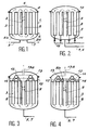
- FIGS. 1 to 4 are sectional views of devices designed according to the invention.
- the device is in the form of a cylindrical enclosure 1 with domed bottoms 2.2a.
- This enclosure contains the filter elements consisting of a set of bundles 3 grouping hollow fibers of ultra or micro-filtration of the "internal skin” type, that is to say in which the filtration takes place from the inside. outward of the fiber.
- These beams are, in the example treated in Figure 1, arranged between two floors 4,4a.
- the device is supplied with liquid, water for example, to be filtered, by a pipe 5 opening at the base of the device.
- the treated water, or permeate is evacuated from the inside to the outside of a bundle by means of orifices made in its envelope and evacuated from the device by a pipe 6.
- This pipe ensures the introduction into the device of the fluid used for backwashing.
- the appliance is emptied by a pipe 7.
- a space constituted in the example treated, by a conduit 8 in which the motor element is disposed, such as pump or propellers 9, intended to ensure in the device the recirculation of the liquid to be filtered.
- the conduit 8 is flush with the upper and lower floors, the volumes thus released by the domed bottoms 2.2a forming, under these conditions, zones for collecting the recirculation inlet and outlet of the modules.
- the apparatus comprises a single floor 10 with which the bundles 3 are made integral, provided for this purpose with a casing fixed by its upper edge to the floor 10.
- the permeate is collected by a perforated tube 11, placed in the center of each bundle and the various tubes 11 for collecting the permeate are connected to a single collector 12 for discharging the permeate outside. of the device, this collector also serving as a pipe for supplying the device with backwashing fluid.
- the apparatus of FIG. 3 differs from the previous one only in the arrangement of a permeate evacuation manifold 13, provided inside the apparatus, supplying an evacuation pipe 13a and collecting the permeate drained by the tubes 11 of fiber bundles.
- FIG. 4 shows an apparatus with a single floor 10, improved according to the invention, in which the duct 8 where the means 9, pump or turbine is housed, ensuring the recirculation of the liquid to be filtered, is extended above the floor 10, of a height 8b, thus allowing the formation of a water reserve 14, which is charged, represents a volume greater than the internal volume of the fibers, and ensures a displacement of the cake and the scanning of the fibers, by simple emptying, of the device.
Description
La présente invention concerne des perfectionnements apportés aux appareils destinés à l'ultra ou micro-filtration de liquides, notamment d'eau, au moyen de membranes constituées par des fibres regroupées en faisceaux de forme tubulaire, dans lesquels la filtration se fait de l'intérieur vers l'extérieur de la fibre ("peau interne").The present invention relates to improvements made to apparatuses intended for ultra or micro-filtration of liquids, in particular of water, by means of membranes constituted by fibers grouped in bundles of tubular shape, in which filtration is carried out inside to outside of the fiber ("inner skin").
De tels appareils se présentent sous la forme d'une enceinte cylindrique dont les fonds sont bombés et dans laquelle les faisceaux d'éléments filtrants sont, soit disposés entre deux planchers superposés, soit rendus solidaires d'un plancher unique.Such devices are in the form of a cylindrical enclosure whose bottoms are curved and in which the bundles of filter elements are either arranged between two superposed floors, or made integral with a single floor.
Ces appareils sont alimentés en liquide, tel qu'eau à filtrer, et le procédé nécessite une recirculation qui est nécessairement très importante, en raison de la conception de l'élément filtrant et qui peut atteindre dix fois le débit de production, pour assurer un balayage efficace de l'intérieur des fibres constituant les faisceaux.These devices are supplied with liquid, such as water to be filtered, and the process requires recirculation which is necessarily very significant, due to the design of the filter element and which can reach ten times the production rate, to ensure a efficient scanning of the interior of the fibers making up the bundles.
En outre, ces fibres doivent, à intervalles plus ou moins rapprochés, être débarrassées des particules déposées en surface pendant la filtration par un lavage au moyen d'eau. Ce lavage, appelé rétrolavage, est produit par inversion du sens des pressions dans l'appareil, donc par inversion du sens de l'écoulement au travers de la paroi des fibres, ce qui provoque le décollement de ces particules.In addition, these fibers must, at more or less frequent intervals, be freed from the particles deposited on the surface during filtration by washing with water. This washing, called backwashing, is produced by reversing the direction of pressure in the device, therefore by reversing the direction of flow through the fiber wall, which causes these particles to come off.
Suivant la technique habituelle, le ou les éléments moteurs de la recirculation, tels que postes de pompage, turbines, hélices ou l'équivalent sont placés en dehors de l'appareil.According to the usual technique, the driving element or elements of the recirculation, such as pumping stations, turbines, propellers or the equivalent are placed outside the device.
Conformément à l'invention et suivant l'une de ses caractéristiques, ce ou ces éléments sont placés dans l'appareil et, avantageusement, placés dans un conduit axial qui est relié au plancher, ou aux planchers, supportant les éléments filtrants.According to the invention and according to one of its characteristics, this or these elements are placed in the device and, advantageously, placed in an axial duct which is connected to the floor, or to the floors, supporting the filter elements.
Suivant une autre caractéristique de l'invention, le fond supérieur de l'appareil comporte une réserve d'eau permettant d'assurer le rinçage final des fibres par simple vidange de l'appareil.According to another characteristic of the invention, the upper bottom of the device has a water reserve allowing the final rinsing of the fibers by simple emptying of the device.
Les divers caractéristiques et avantages de l'invention ressortiront de la description, qui va suivre, de quelques unes de ses formes possibles de réalisation, étant bien entendu qu'il s'agit uniquement d'exemples non limitatifs et que toutes autres formes, proportions et dispositions pourraient être adoptées sans sortir du cadre de l'invention.The various characteristics and advantages of the invention will emerge from the description which follows of some of its possible embodiments, it being understood that these are only nonlimiting examples and that all other forms, proportions and provisions could be adopted without departing from the scope of the invention.
Au cours de cette description, on se réfère au dessin ci-joint dont les Figures 1 à 4 sont des vues en coupe d'appareils conçus suivant l'invention.During this description, reference is made to the attached drawing, FIGS. 1 to 4 are sectional views of devices designed according to the invention.
Comme connu, l'appareil se présente sous la forme d'une enceinte cylindrique 1 à fonds bombés 2,2a. Cette enceinte contient les éléments filtrants consistant en un ensemble de faisceaux 3 regroupant des fibres creuses d'ultra ou de micro-filtration de type "peau interne", c'est-à-dire dans lesquelles la filtration s'opère de l'intérieur vers l'extérieur de la fibre. Ces faisceaux sont, dans l'exemple traité à la Figure 1, disposés entre deux planchers 4,4a.As known, the device is in the form of a cylindrical enclosure 1 with domed bottoms 2.2a. This enclosure contains the filter elements consisting of a set of
Dans ce cas, l'appareil est alimenté en liquide, eau par exemple, à filtrer, par une canalisation 5 débouchant à la base de l'appareil. L'eau traitée, ou perméat, est évacuée de l'intérieur vers l'extérieur d'un faisceau au moyen d'orifices ménagés dans son enveloppe et évacuée de l'appareil par une canalisation 6. Cette canalisation assure l'introduction dans l'appareil du fluide servant au rétrolavage. Enfin, la vidange de l'appareil s'opère par une canalisation 7.In this case, the device is supplied with liquid, water for example, to be filtered, by a
Conformément à l'invention, est prévu ou ménagé, dans l'appareil et suivant son axe, entre les faisceaux de modules filtrants, un espace, constitué dans l'exemple traité, par un conduit 8 dans lequel est disposé l'élément moteur, tel que pompe ou hélices 9, destiné à assurer dans l'appareil la recirculation du liquide à filtrer.In accordance with the invention, there is provided or arranged, in the apparatus and along its axis, between the bundles of filter modules, a space, constituted in the example treated, by a
Le conduit 8 affleure les planchers haut et bas, les volumes ainsi dégagés par les fonds bombés 2,2a formant, dans ces conditions, des zones de collecte de la recirculation entrée et sortie des modules.The
Cette disposition suivant l'invention, grâce à la suppression de tout organe, moyen ou dispositif, extérieur à l'appareil, offre en particulier les avantages suivants :
- réduction de la surface au sol d'une unité de filtration, donc augmentation de production de liquide traité par unité de surface,
- réduction du coût de réalisation par suppression d'éléments tels que tuyauterie, supports etc...,
- réduction de l'énergie consommée, le gain réalisé correspondant aux pertes de charge créées par les tuyauteries supprimées.
- reduction of the surface area on the ground of a filtration unit, therefore increase in the production of treated liquid per unit area,
- reduction in the cost of production by removing elements such as piping, supports, etc.,
- reduction of the energy consumed, the gain realized corresponding to the pressure losses created by the eliminated pipes.
Suivant la forme de réalisation représentée à la Figure 2, l'appareil comporte un plancher unique 10 duquel sont rendus solidaires les faisceaux 3, munis dans ce but d'un carter fixé par sa tranche supérieure au plancher 10.According to the embodiment shown in FIG. 2, the apparatus comprises a
Dans ce cas, comme il est connu, le perméat est recueilli par un tube perforé 11, placé au centre de chaque faisceau et les différents tubes 11 de collecte du perméat sont reliés à un collecteur unique 12 d'évacuation du perméat à l'extérieur de l'appareil, ce collecteur servant également de canalisation d'amenée à l'appareil du fluide de rétrolavage.In this case, as is known, the permeate is collected by a
L'appareil de la Figure 3 ne diffère du précédent que par la disposition d'un collecteur 13 d'évacuation du perméat, prévu à l'intérieur de l'appareil, alimentant une tuyauterie d'évacuation 13a et recueillant le perméat drainé par les tubes 11 des faisceaux de fibres.The apparatus of FIG. 3 differs from the previous one only in the arrangement of a
La Figure 4 montre un appareil à plancher unique 10, perfectionné suivant l'invention, dans lequel le conduit 8 où est logé le moyen 9, pompe ou turbine, assurant la recirculation du liquide à filtrer, est prolongé au-dessus du plancher 10, d'une hauteur 8b, permettant ainsi la formation d'une réserve d'eau 14, qui est en charge, représente un volume supérieur au volume intérieur des fibres, et assure un déplacement du gâteau et le balayage des fibres, par simple vidange, de l'appareil.FIG. 4 shows an apparatus with a
Claims (4)
- Apparatus intended for the ultrafiltration or microfiltration of liquids, especially water, by means of membranes composed of fibres grouped into bundles of tubular shape, the filtration taking place, with an active recirculation of the liquid to be filtered, from the inside to the outside of the fibre, such an apparatus being in the form of a cylindrical container (1) having domed ends (2, 2a), in which the bundles of filtering elements (3) are either disposed between two plates (4, 4a) one above the other, or are firmly fixed to a single plate (10), this apparatus being characterized in that the means (9) intended for assuring the recirculation of the liquid during filtration are situated inside the apparatus.
- Apparatus according to Claim 1, characterized in that the means are situated in an axial duct (8), open at both ends and connected to the plate or plates which support the filtering elements.
- Apparatus according to Claim 2, characterized in that it comprises, in its upper part, a reserve of liquid (14) enabling the cleaning of the fibres to be carried out by simply emptying the apparatus.
- Apparatus according to Claim 3, characterized in that the reserve of liquid is formed by the continuation of the axial duct (8) into the zone situated above the plate (10).
Priority Applications (1)
| Application Number | Priority Date | Filing Date | Title |
|---|---|---|---|
| AT91400752T ATE102502T1 (en) | 1990-03-23 | 1991-03-20 | IMPROVEMENTS TO MEMBRANE FILTERS FOR ULTRA OR MICROFILTRATION OF LIQUIDS, ESPECIALLY WATER. |
Applications Claiming Priority (2)
| Application Number | Priority Date | Filing Date | Title |
|---|---|---|---|
| FR9003748 | 1990-03-23 | ||
| FR9003748A FR2659870B1 (en) | 1990-03-23 | 1990-03-23 | IMPROVEMENTS IN MEMBRANE FILTERS FOR ULTRA OR MICRO-FILTRATION OF LIQUIDS, ESPECIALLY WATER. |
Publications (2)
| Publication Number | Publication Date |
|---|---|
| EP0448466A1 EP0448466A1 (en) | 1991-09-25 |
| EP0448466B1 true EP0448466B1 (en) | 1994-03-09 |
Family
ID=9395054
Family Applications (1)
| Application Number | Title | Priority Date | Filing Date |
|---|---|---|---|
| EP91400752A Revoked EP0448466B1 (en) | 1990-03-23 | 1991-03-20 | Improvements of membrane filters for ultrafiltration or microfiltration of liquids, in particular of water |
Country Status (8)
| Country | Link |
|---|---|
| US (1) | US5096583A (en) |
| EP (1) | EP0448466B1 (en) |
| JP (1) | JPH04222622A (en) |
| AR (1) | AR245012A1 (en) |
| AT (1) | ATE102502T1 (en) |
| DE (2) | DE448466T1 (en) |
| ES (1) | ES2025550T3 (en) |
| FR (1) | FR2659870B1 (en) |
Families Citing this family (15)
| Publication number | Priority date | Publication date | Assignee | Title |
|---|---|---|---|---|
| KR930019861A (en) * | 1991-12-12 | 1993-10-19 | 완다 케이. 덴슨-로우 | Coating method using dense gas |
| US5451317A (en) * | 1994-09-08 | 1995-09-19 | Kubota Corporation | Solid-liquid separator |
| US5569381A (en) * | 1995-05-24 | 1996-10-29 | Spokane Industries, Inc. | Upflow clarifier |
| US5611924A (en) * | 1995-08-29 | 1997-03-18 | Osborne; William | High flow filter system |
| US5914041A (en) * | 1996-09-03 | 1999-06-22 | Nate International | Channel based reverse osmosis |
| DE19702902C1 (en) * | 1997-01-28 | 1998-02-12 | Uwatech Gmbh | Efficient cylindrical membrane separator with integral electrical circulation pump, suitable for portable use |
| SE510324C2 (en) * | 1997-06-19 | 1999-05-10 | Electrolux Ab | Method and apparatus for purifying a fluid |
| FR2810256B1 (en) * | 2000-06-14 | 2003-03-07 | Vallee De L Aigues S I V A Soc | FILTRATION DEVICE INCLUDING A CIRCULATION LOOP |
| US7141167B2 (en) * | 2001-04-23 | 2006-11-28 | N F T Nanofiltertechnik Gmbh | Filter device |
| FR2903617B1 (en) * | 2006-07-17 | 2009-03-20 | Vallee De L Aigues Sarl Soc In | METHOD FOR CONTROLLING A TANGENTIAL FILTRATION DEVICE AND CORRESPONDING DEVICE |
| EA200970717A1 (en) * | 2007-02-14 | 2010-04-30 | ДиИксВи ВОТЕР ТЕКНОЛОДЖИС, ЭлЭлСи | DEPTH OPEN MEMBRANE FOR WATER INTAKE |
| US8231784B2 (en) * | 2009-03-12 | 2012-07-31 | Fluid Equipment Development Company, Llc | Continuous process batch-operated reverse osmosis system with in-tank membranes and circulation |
| MX2012008953A (en) | 2010-02-04 | 2012-11-23 | Dxv Water Technologies Llc | Water treatment systems and methods. |
| US10513446B2 (en) | 2014-10-10 | 2019-12-24 | EcoDesal, LLC | Depth exposed membrane for water extraction |
| IL308177A (en) * | 2021-05-06 | 2023-12-01 | Prosper Tech Llc | Systems and methods of gas infusion for wastewater treatment |
Family Cites Families (9)
| Publication number | Priority date | Publication date | Assignee | Title |
|---|---|---|---|---|
| US3541004A (en) * | 1968-06-10 | 1970-11-17 | Abcor Inc | Cleaning an ultrafilter with an elongated,reciprocating,agitator |
| US3821108A (en) * | 1972-05-23 | 1974-06-28 | S Manjikian | Reverse osmosis or ultrafiltration module |
| US4540490A (en) * | 1982-04-23 | 1985-09-10 | Jgc Corporation | Apparatus for filtration of a suspension |
| US4414113A (en) * | 1982-09-29 | 1983-11-08 | Ecodyne Corporation | Liquid purification using reverse osmosis hollow fibers |
| US4756875A (en) * | 1983-09-29 | 1988-07-12 | Kabushiki Kaisha Toshiba | Apparatus for filtering water containing radioactive substances in nuclear power plants |
| JPS61274709A (en) * | 1985-05-29 | 1986-12-04 | Ebara Corp | Hollow yarn membrane filter apparatus |
| US4876006A (en) * | 1985-10-08 | 1989-10-24 | Ebara Corporation | Hollow fiber filter device |
| DE3709432A1 (en) * | 1987-03-21 | 1988-10-06 | Fresenius Ag | CAPILLARY FILTER ARRANGEMENT FOR THE STERILIZATION OF LIQUID MEDIA |
| US4744900A (en) * | 1987-04-20 | 1988-05-17 | Bratt Russell I | Reverse osmosis membrane container |
-
1990
- 1990-03-23 FR FR9003748A patent/FR2659870B1/en not_active Expired - Fee Related
-
1991
- 1991-03-20 DE DE199191400752T patent/DE448466T1/en active Pending
- 1991-03-20 EP EP91400752A patent/EP0448466B1/en not_active Revoked
- 1991-03-20 DE DE69101327T patent/DE69101327T2/en not_active Revoked
- 1991-03-20 AT AT91400752T patent/ATE102502T1/en not_active IP Right Cessation
- 1991-03-20 ES ES91400752T patent/ES2025550T3/en not_active Expired - Lifetime
- 1991-03-20 US US07/672,419 patent/US5096583A/en not_active Expired - Fee Related
- 1991-03-22 JP JP3083103A patent/JPH04222622A/en active Pending
- 1991-03-22 AR AR91319297A patent/AR245012A1/en active
Also Published As
| Publication number | Publication date |
|---|---|
| FR2659870A1 (en) | 1991-09-27 |
| JPH04222622A (en) | 1992-08-12 |
| ATE102502T1 (en) | 1994-03-15 |
| US5096583A (en) | 1992-03-17 |
| ES2025550T1 (en) | 1992-04-01 |
| FR2659870B1 (en) | 1993-03-12 |
| DE69101327D1 (en) | 1994-04-14 |
| ES2025550T3 (en) | 1994-05-01 |
| EP0448466A1 (en) | 1991-09-25 |
| DE448466T1 (en) | 1992-02-27 |
| AR245012A1 (en) | 1993-12-30 |
| DE69101327T2 (en) | 1994-06-16 |
Similar Documents
| Publication | Publication Date | Title |
|---|---|---|
| EP0448466B1 (en) | Improvements of membrane filters for ultrafiltration or microfiltration of liquids, in particular of water | |
| EP0334774B1 (en) | Integrated apparatus for biospecifically purifying a liquid containing cells | |
| CA2017588C (en) | Method and an improved apparatus for separating solid particles from a liquid | |
| CA1166583A (en) | Settling means for a fluid | |
| CN101472670A (en) | Running method of membrane separation device | |
| EP0025628A2 (en) | Filter for liquids with automatic cleaning of the filtration element | |
| FR2647362A1 (en) | TUBULAR FILTER ELEMENT FOR OVERFLOW FILTRATION | |
| EP0120750A1 (en) | Device for tangential filtration and installation containing this device | |
| CA2027091C (en) | Liquid filtering device, namely for swimming pools | |
| FR2594045A1 (en) | SELF-CLEANING FILTER, AND STEAM CONDENSER INLET WATER BOX COMPRISING SUCH A FILTER. | |
| FR2802115A1 (en) | PERMEATION INSTALLATION | |
| JPH0910561A (en) | Hollow fiber membrane element and its use method and filter | |
| FR2548047A1 (en) | PRESSURE REACTOR WITH SELF-CLEANING FILTERING DEVICE | |
| FR2630657A1 (en) | TANGENTIAL FILTRATION APPARATUS | |
| FR2745195A1 (en) | RETENTION FILTER, INSTALLATION AND PROCESS FOR TREATING EFFLUENTS | |
| FR2576805A1 (en) | Apparatus for tangential filtration | |
| FR2746033A1 (en) | SELF-CLEANING FILTER FOR LIQUID | |
| JP3951549B2 (en) | Cylindrical membrane element and cleaning method thereof | |
| SU1613138A1 (en) | Filter | |
| WO1985004113A1 (en) | Improvement to vacuum rotary filters with horizontal filtration plane | |
| RU8283U1 (en) | FILTER BASED ON MEMBRANE ELEMENTS | |
| EP1349643A1 (en) | Backwashing of a hollow fibre filter operating in frontal mode | |
| RU13162U1 (en) | HOUSEHOLD FILTER FOR CLEANING WATER | |
| FR3076739A1 (en) | HOT FIBER WATER FILTRATION ELEMENT AND FILTRATION MODULE INTEGRATING SUCH A FILTRATION ELEMENT | |
| FR2768940A1 (en) | REGENERABLE FILTER FOR LIQUIDS, ESPECIALLY FOOD |
Legal Events
| Date | Code | Title | Description |
|---|---|---|---|
| PUAI | Public reference made under article 153(3) epc to a published international application that has entered the european phase |
Free format text: ORIGINAL CODE: 0009012 |
|
| AK | Designated contracting states |
Kind code of ref document: A1 Designated state(s): AT BE DE ES NL |
|
| TCNL | Nl: translation of patent claims filed | ||
| TCAT | At: translation of patent claims filed | ||
| DET | De: translation of patent claims | ||
| 17P | Request for examination filed |
Effective date: 19920201 |
|
| 17Q | First examination report despatched |
Effective date: 19930820 |
|
| GRAA | (expected) grant |
Free format text: ORIGINAL CODE: 0009210 |
|
| AK | Designated contracting states |
Kind code of ref document: B1 Designated state(s): AT BE DE ES NL |
|
| REF | Corresponds to: |
Ref document number: 102502 Country of ref document: AT Date of ref document: 19940315 Kind code of ref document: T |
|
| PGFP | Annual fee paid to national office [announced via postgrant information from national office to epo] |
Ref country code: NL Payment date: 19940331 Year of fee payment: 4 Ref country code: AT Payment date: 19940331 Year of fee payment: 4 |
|
| REF | Corresponds to: |
Ref document number: 69101327 Country of ref document: DE Date of ref document: 19940414 |
|
| REG | Reference to a national code |
Ref country code: ES Ref legal event code: FG2A Ref document number: 2025550 Country of ref document: ES Kind code of ref document: T3 |
|
| PLBI | Opposition filed |
Free format text: ORIGINAL CODE: 0009260 |
|
| 26 | Opposition filed |
Opponent name: OMNIUM DE TRAITEMENTS ET DE VALORISATION OTV Effective date: 19941209 |
|
| PGFP | Annual fee paid to national office [announced via postgrant information from national office to epo] |
Ref country code: ES Payment date: 19950223 Year of fee payment: 5 |
|
| NLR1 | Nl: opposition has been filed with the epo |
Opponent name: OMNIUM DE TRAITMENTS ET VALORISATION OTV |
|
| PG25 | Lapsed in a contracting state [announced via postgrant information from national office to epo] |
Ref country code: AT Effective date: 19950320 |
|
| PGFP | Annual fee paid to national office [announced via postgrant information from national office to epo] |
Ref country code: BE Payment date: 19950404 Year of fee payment: 5 |
|
| PGFP | Annual fee paid to national office [announced via postgrant information from national office to epo] |
Ref country code: DE Payment date: 19950522 Year of fee payment: 5 |
|
| PG25 | Lapsed in a contracting state [announced via postgrant information from national office to epo] |
Ref country code: NL Effective date: 19951001 |
|
| NLV4 | Nl: lapsed or anulled due to non-payment of the annual fee |
Effective date: 19951001 |
|
| RDAG | Patent revoked |
Free format text: ORIGINAL CODE: 0009271 |
|
| STAA | Information on the status of an ep patent application or granted ep patent |
Free format text: STATUS: PATENT REVOKED |
|
| 27W | Patent revoked |
Effective date: 19951028 |