EP0448049B1 - Packet transfer regulating apparatus - Google Patents
Packet transfer regulating apparatus Download PDFInfo
- Publication number
- EP0448049B1 EP0448049B1 EP91104248A EP91104248A EP0448049B1 EP 0448049 B1 EP0448049 B1 EP 0448049B1 EP 91104248 A EP91104248 A EP 91104248A EP 91104248 A EP91104248 A EP 91104248A EP 0448049 B1 EP0448049 B1 EP 0448049B1
- Authority
- EP
- European Patent Office
- Prior art keywords
- packet
- route
- congested state
- switching nodes
- information
- Prior art date
- Legal status (The legal status is an assumption and is not a legal conclusion. Google has not performed a legal analysis and makes no representation as to the accuracy of the status listed.)
- Expired - Lifetime
Links
Images


Classifications
-
- H—ELECTRICITY
- H04—ELECTRIC COMMUNICATION TECHNIQUE
- H04L—TRANSMISSION OF DIGITAL INFORMATION, e.g. TELEGRAPHIC COMMUNICATION
- H04L45/00—Routing or path finding of packets in data switching networks
-
- H—ELECTRICITY
- H04—ELECTRIC COMMUNICATION TECHNIQUE
- H04L—TRANSMISSION OF DIGITAL INFORMATION, e.g. TELEGRAPHIC COMMUNICATION
- H04L45/00—Routing or path finding of packets in data switching networks
- H04L45/38—Flow based routing
Definitions
- the present invention generally relates to a packet communication network composed of transmission lines for connecting a plurality of terminals and packet-switching nodes connectable to said plurality of terminals, and transmission lines for interconnecting said packet-switching nodes and, more particularly, to a packet transfer regulating apparatus for alleviating congested states of said packet-switching nodes and transmission lines.
- a packet communication network is comprised of transmission lines for connecting terminals and packet-switching nodes connectable to said plurality of terminals, and transmission lines for interconnecting said packet-switching nodes with each other.
- the terminal is a source for generating a wide variety of information such as data, image data, audio data and so on.
- the packet-switching node is adapted to extract priority information contained in a packet from a terminal and to add a new transfer destination address to the header of the priority information to form a packet format or to judge a route to which data is transferred.
- the packet-switching node extracts from a probability standpoint communication information generated by the terminal and converts it to packet data to effect the communication.
- highly efficient resource administration is realized on the basis of large grouping effect within the network.
- Respective packets are temporarily stored in a transfer queuing buffer provided within the node, thereby keeping constant the band width of the transmission line.
- Such a congested state may occur in the transmission line or in the packet-switching node.
- a control operation is performed so that the flow of packets to the congestion occurrence point is regulated (stopped) and the flow of packets is regulated so that it becomes less than the flow of packets out of the congestion occurrence point.
- This control operation is what might be called a transfer regulation. The following two points are considered as points at which the transfer regulation is executed:
- the input point at which excess traffic, which causes congestion, is input to the network is detected at the congestion occurrence point.
- the input is then regulated at that input point without delay (zero time).
- a regulation instruction is transmitted to the input point with a constant delay time.
- Concentration of traffic is not limited to the excess input of one input (traffic), but may occur when several inputs are accidentally overlapped. When this occurs, the overlapped state may cease to exist automatically after a certain excessive state. Accordingly, the system for regulating traffic flowing to the input point of the network is not always optimum.
- a system for regulating only a communication (traffic) which causes congestion is ideal because invalid and excessive regulation occurs when it is extended to communications other than that which passes through the congested transmission line.
- the first is a direct regulation system.
- an input source in which an excessive flow occurs at a congestion occurrence point is specified and a regulation instruction is issued directly to the input source, and in this system, a regulation achieving time and a regulation extending range are both approximately ideal.
- the second system is a transmission line regulation system.
- an input transmission line is regulated from a congestion occurrence point in the upstream direction (input direction), whereby a quasi-congestion occurs in the preceding node or transmission line, and regulation is sequentially extended in the upstream direction to the traffic input point.
- call identifying numbers such as the logical channel numbers of individual packets must be detected, and sending nodes of such calls must be detected.
- the first example of the prior art has the substantial problem that an enormous hardware and a complicated processing are needed. Thus, this conventional system cannot cope with a future enlarged network.
- the second example of the prior art is fundamentally a system for regulating traffic from a transmission line which becomes an input to a transmission line when a congestion occurs in a certain transmission line.
- This system is described with reference to the packet communication network of Figure 2, which is similar to that of Figure 1. If a congestion occurs in transmission line 102 3 accommodated in a certain packet-switching node 101 3 , the regulation will be propagated first to transmission line 102 3 ; then to transmission lines 102 2 , 102 5 , and 102 6 ; and finally to transmission lines 102 1 , and 102 4 . In other words, although it is originally requested that only communications #1 to #3 be regulated, the regulation is also propagated to communications #4 to #6, thus lowering the throughput of the entire circuit.
- the second example of the prior art has the substantial disadvantage that congestion in the entire circuit cannot be alleviated. Furthermore, traffics are stored in the respective stages so that, in addition to the transmitting time, a time in which buffers of respective stages consume is needed also as the regulation achieving time.
- an object of the present invention is to provide an apparatus for regulating packet transfer in which only a route passing through a transmission line in which a congestion occurs can be regulated by a simple control processing and the route can be readily restored from the congested state.
- the present invention thus provides a packet transfer regulating apparatus for regulating packet transfer in a packet communication network composed of: (i) transmission lines for interconnecting a plurality of packet-switching nodes, and (ii) a plurality of terminals connected to said packet-switching nodes; said packet transfer regulating apparatus comprising controlling means provided in each of said packet-switching nodes for controlling a congested state of at least one of a plurality of routes, each of which routes can be uniquely discriminated and is defined by arbitrarily selecting at least one of said packet-switching nodes and at least one of said transmission lines in said packet communication network in an arbitrary order such that the packet-switching nodes and the transmission lines thus selected are connected alternately together; each of said controlling means being adapted to control the congested state only of those routes in the packet communication network which pass through the one of said packet-switching nodes respectively containing said controlling means.
- the controlling means are composed of a route memory unit, a congested stated detecting unit, a congested state informing unit, a route identifying unit and a route control unit. They are described below.
- the route memory unit memorizes which route of respective routes is involved or used in each transmission line within the packet communication network.
- the congested state detecting unit detects the congested state of a transmission line connected to its own packet-switching node or of a route, for example, a so-called congestion state.
- the congested state informing unit transmits the transmission line or route congested state detected by the congested state detecting unit to other packet-switching nodes.
- the congested state informing unit memorizes identifying information of a sending node of a route at every route involved in each transmission line. This congested state informing unit transmits a congested state of each transmission line or route only to the corresponding sending node.
- the route identifying unit is provided when the congested state detecting unit detects a congested state of a transmission line.
- the route identifying unit receives congested state information from other packet-switching nodes, retrieves a route involved in a transmission line corresponding to the received information and identifies a route accommodated by its own packet-switching node from the retrieved route.
- the route control unit controls the congested state of the route identified by the route identifying unit or directly transmitted as the congested state information on the bases of the received congested state information.
- This control operation is realized by regulating the transmission of packet data transferred in the identified route or by cancelling the regulation.
- control operation is realized as an operation in which a terminal using the route is identified and an input of packet data transmitted by the identified terminal is regulated or the regulation is cancelled.
- traffic passing the transmission line is classified into the aforementioned "route" and grouped, whereby an object whose congestion is to be supervised is limited to far fewer routes than in the prior art in which several hundreds to several thousands of congested communications should be separately supervised. Then, while administering the route of its own packet-switching node, each packet-switching node controls the congested states of the respective routes to thereby regulate only the traffic passing through transmission line in which congestion occurs in units of route. Therefore, the route can be regulated very efficiently by a simple control operation.
- the present invention is based on a packet communication network composed of transmission lines for connecting a plurality of terminals accommodated in a packet-switching node and transmission lines for connecting packet-switching nodes with each other.
- a uniquely identifiable route is defined. This route is constructed by selecting an arbitrary packet existing within the network and an arbitrary transmission line in an arbitrary order.
- the present invention is characterized in that, while administering a route accommodated by its own packet-switching node, each packet-switching node controls the congested state of each route.
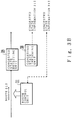
- FIGS 3A and 3B are block diagrams showing the principles of the present invention.
- Figure 3A is a principle block diagram of components of the present invention constructed in each packet-switching node in the first mode of the present invention.
- a route memory unit 301 memorizes which of the routes within the defined network is involved in every transmission line 306 within the packet communication network.
- a congested state detecting unit 302 detects a congested state of a transmission line 306 accommodated within its own packet-switching node. This detecting unit 302 detects either an occurrence of a congested state of the transmission line 306 accommodated within its own packet-switching node or a cancellation of a congestion state. Incidentally, the detecting unit 302 may be arranged so as to detect an intermediate congested state.
- a congested state informing unit 303 informs other packet-switching nodes of the congested state of transmission line 306 detected by the congested state detecting unit 302 as congested state information 307.
- the congested state information 307 is either the congested state occurrence information which indicates the occurrence of a congested state in transmission line 306 detected by the congested state detecting unit 302 or congested state cancellation information which indicates that the congested state occurring in the transmission line 306 accommodated within its own packet-switching node is cancelled.
- the present invention may be modified such that the congested state informing unit 303 can transmit the intermediate congested state to other packet-switching nodes.
- a route identifying unit 304 receives congested state information 307 from other packet-switching nodes and retrieves the route involved in the transmission line corresponding to the congested state information from the route memory unit 301 to thereby identify a route 308 accommodate by its own packet-switching node from the retrieved routes.
- a route control unit 305 performs the control of the congested state of route 308 identified by the route identifying unit 304 on the basis of the aforementioned congested state information 307 thus received.
- Figure 3B is a principle block diagram of constituents of the second mode of the present invention constructed in each packet-switching node.
- a congested state detecting unit 309 directly detects the congested state of a route 313 (not the transmission line) accommodated within its own packet-switching node.
- the congested state detecting unit 309 may be composed of a flow supervisory unit which supervises the flow of packet data in route 313 accommodated within its own packet-switching node and a detecting unit which detects the congested state of the route by comparing the flow supervised by the supervisory unit with traffic amount set when the call in route 313 is set. Then, the congested state detecting unit 309 detects either the occurrence of a congested state of route 309 or the cancellation of a congested state.
- the present invention may be modified so as to detect an intermediate congested state.
- a congested state informing unit 310 informs other packet-switching nodes of the congested state of route 313 detected by the congested state detecting unit 309 as congested state information 312.
- the congested state information 312 might be either congested state occurrence information indicating that a congested state occurs, for example, in route 313 or congested state cancellation information indicating that a congested state occurring in route 313 is cancelled.
- the congested state informing unit 310 may be modified so as to transmit the intermediate congested state to another packet-switching node.
- a route control unit 311 receives congested state information 312 from other packet-switching nodes and controls the congested state of route 313 accommodated within its own packet-switching node in routes corresponding to the congested state information.
- the first and second mode of the present invention may be arranged such that route control unit 305 or 311 determines whether or not the terminal utilizing route 308 or 313, whose congested state is to be controlled, is accommodated within its own packet-switching node. If it is, the input of packet data transmitted by the terminal is regulated or the regulation of the input of packet data is cancelled.
- the first and second mode of the present invention may include a sending packet-switching node memory unit for each route, as described below.
- This memory unit memorizes a sending packet-switching node, which is a starting point of each route, at every route 308 or 313 accommodated within its own packet-switching node.
- the congested state informing unit 303 or 310 retrieves a sending packet-switching node corresponding to route 308 accommodated within transmission line 306 detected by congested state detecting unit 302, or corresponding to route 313 detected by congested state detecting unit 309, from the sending packet-switching node memory unit for each route, and transmits the congested state information 307 or 312 to the retrieved sending packet-switching node.
- traffic passing the transmission line is classified into the aforementioned "routes" and grouped, whereby objects whose congestion is to be supervised can be reduced to far fewer routes than in the prior art, in which congestion states of several hundreds to several thousands of communications should be supervised separately. Then, while administering the route accommodated by its own packet-switching node, each packet-switching node can regulate only the traffic passing the congested transmission line in units of route by controlling the congested states of respective routes. Thus, the route can be regulated very efficiently.
- a congestion is an example of a congested state
- information indicating the occurrence of such a congestion is transmitted to other packet-switching nodes as congested state information.
- the information of this case is transmitted in the form of, for example, a transmission line number and a flag indicating the occurrence of the congestion state.
- the route identifying unit 304 retrieves the route included in the transmission line corresponding to the congested state information 307 and identifies route 308 accommodated within its own packet-switching node of the thus retrieved nodes. Then, the route control unit 305 executes the congested state control only to the thus identified route 308 on the basis of the congested state information 307.
- packet data of routes other than the corresponding route are not regulated and transferred in an ordinary fashion so that propagation of a congested state such as a congestion to other packet-switching nodes can be minimized.
- each packet-switching node need not grasp the status of all communication concerning each packet-switching node, but must grasp only the state of the transmission line accommodated within its own packet-switching node by the congested state informing unit 310 corresponding to that transmission line, thereby effecting a very efficient supervision.
- the congested state can be informed only by the information of the transmission line, thereby efficiently transmitting the congested state information 307 to other packet-switching node.
- the detection of the congested state is directly performed by the congested state detecting unit 309 not in units of transmission line but in units of route unit as shown in Figure 3B, and the congested state information 312 is transmitted by the congested state informing unit 310 in units of route.
- the amount of information in the congested state information processing is greater than in the first embodiment of the present invention in which the information of the transmission line is transmitted.
- the number of routes is much smaller than the number of individual communications, making it possible to considerably reduce the amount of information compared with the examples of the prior art.
- processing to identify the route from the information of the transmission line is not needed.
- respective packet-switching nodes independently perform parallel regulating operations, enabling regulation to be readily executed.
- route control unit 305 or 311 determines whether or not the terminal utilizing route 308 or 313, whose congested state is to be controlled, is accommodated within its own packet-switching node. If the terminal is accommodated within its own packet-switching node, the input regulation of the packet data transmitted from that terminal is performed or the input regulation is cancelled, whereby the input regulation can be directly and effectively executed on the terminals participating in the communications performed via the congested transmission line.
- congested state information 307 or 312 can be directly transmitted to the sending packet-switching node corresponding to route 313 detected by the congested state detecting unit 309 or route 308 accommodated within the transmission line. Consequently, the congested state information can be readily propagated only to the sending packet-switching node of the corresponding route, whereby redundant information can be prevented from being transferred to other nodes. Therefore, the congested state information can be transmitted efficiently and the congestion can be readily cancelled.
- first and second modes are described as independent arrangements, if the respective arrangements are properly combined in response to the circumstances of the network, it is possible to realize optimum congested state control.
- the first embodiment is described first.
- This embodiment relates to a kind of transmission line regulation system which regulates only a necessary "route" (referred to later) involved in the input transmission line for the node in the upstream of the congestion occurrence point.
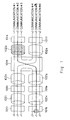
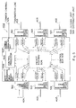
- FIG. 4 shows the entire arrangement of a packet communication network.
- a packet communication network 401 has a circuit configuration such that packet-switching nodes (hereinafter simply referred to as nodes) 402 A , 402 B , 402 C and 402 D are mutually connected by transmission lines 403 AB , 403 AD , 403 BC , 403 BD , 403 DC .
- Node 402 A for example, accommodates a plurality of terminals 404 A1 to 404 An .
- node 402 B accommodates a terminal 404 B1 and node 402 C accomodates, for example, a plurality of terminals 404 C1 to 404 Cm and a private branch exchange PBX406 C which accommodates internal terminals 407 C1 to 407 CK .
- the node 402 D accommodates, for example, a terminal 404 D1 and a host computer 405 D .
- the network configuration of Figure 4 is described by way of example, and a network configuration of a larger network scale can be constructed in practice.
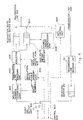
- Figure 5 is a diagram showing in block form nodes 402 A , 402 B , 402 C and 402 D according to the first embodiment of the present invention.
- the second embodiment of the present invention which will be referred to later, has a similar arrangement.
- node 402 A and so on will be simply referred to as node 402
- transmission line 403 AB and so on will be simply referred to as transmission line 403
- terminal 404 A1 and so on will be simply referred to as terminal 404.
- terminal 404 is accommodated by a packet assembly/disassembly unit 502, and transmission line 403 is accommodated by a transmission line interface unit 501.
- Packet data received at the packet assembly/disassembly unit 502 or at the transmission line interface unit 501 is converted into packet data of a common protocol, independent of communication media and is input to a transfer destination judging unit 503.
- the judging unit 503 judges address information added to a packet header, adds new address information to the packet data and transmits the resultant packet data to a packet highway 506.
- a distribution unit 504 selects communication data on the packet highway 506 and transmits the selected communication data to the transmission line interface unit 501.
- a control processor 505 performs control such as call control and network supervision by controlling the transfer destination judging unit 503. Further, the control processor 505 judges a pass line of regulation information, described later, with reference to the route information table TBL1 stored in the route information table memory unit 506. Then, a variety of control data are exchanged between the transmission line accommodating unit 501 and the packet assembly/disassembly unit 502 via a control bus 508. Further, control data are exchanged between the node 402 and other node via a common channel 509 from a common channel signaling unit 507.
- Figure 6 is a schematic diagram showing in block from the transmission line accommodating unit 501 of Figure 5, according to the first embodiment of the present invention.
- packet data are input to an input and output unit 601 from the packet highway 506 through the distribution unit 504 of Figure 5, and fed to a route number extracting unit 602, in which a route number 611 of the "route” (described later) through which the packet data is transmitted, and extracted from the input packet data. Thereafter, the packet data are converted into a protocol suitable for the kinds of communication media by a transmission line encoding unit 603.
- a regulation route table memory unit 604 stores a regulation route table TBL2, described later.
- the contents of this table TBL2 are set by the control processor 505 of Figure 5 through the control bus 508.
- the table TBL2 is accessed by the address of the route number 611 extracted by the route number extracting unit 602, whereby a regulation route flag 613 is output to a selector 605 from the regulation route table memory unit 604.
- the selector 605 selectively connects the packet data converted by the transmission line encoding unit 603 to a pass route queue provided within a pass route queuing buffer 607 or to a regulation route queue provided within a regulation route queuing buffer 606 on the basis of the regulation route flag 612.
- a gate control unit 609 usually allows a gate 610 to select the output of the pass route queuing buffer 607, whereby packet data connected to the pass route queue of the buffer 607 are sequentially transmitted to the transmission line 403 through the gate 610.
- the gate control unit 609 when the gate control unit 609 receives congestion cancel information from the control processor 505 of Figure 5 through the control bus 508, the gate control unit 609 allows the gate 610 to select the output of the restriction route queuing buffer 606 to thereby output the packet data connected to the regulation route queue of the buffer 606 to the transmission line 403. Thereafter, the gate control unit 609 again allows the gate 610 to select the output of the pass route queuing buffer 607.
- a stored amount supervisory unit 608 supervises the number of packet data stored in the pass route queuing buffer 607 and detects a congested state when the number of the packet data exceeds a predetermined value. When the stored amount supervisory unit 608 detects the congested state, the stored amount supervisory unit 608 transmits information to the control processor 505 through the control bus 508.
- the packet data from the transmission line 403 is input in a transmission line decoding unit 611, in which it is decoded and converted into packet data of a common protocol which is independent of the kinds of communication media. Then, the packet data is connected to the receiving queue of a receiving buffer 612 and transmitted to the transfer destination judging unit 503 of Figure 5 via the input and output unit 601.
- FIG 7 is a schematic diagram showing a data format of the route information table TBL1 stored in the route information table memory unit 506 of Figure 5.
- "routes" are defined by sequentially selecting arbitrary nodes and arbitrary transmission lines existing within the network in an arbitrary order and proper route numbers are assigned to respective routes. For example, a route formed of "node 402 A , node 402 B and node 402 D " in that order is endowed with route 1 and a route formed of "node 402 A , node 402 B and node 402 C " is endowed with route 2.
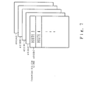
- FIGs 8A and 8B are schematic representations of the data format of the regulation route table TBL2 stored in the regulation route table memory unit 604 ( Figure 6) provided within each transmission line interface unit 501 ( Figure 5) contained in each node 402 ( Figure 4).
- flag "1” or "0” is used to determine whether or not the output of the packet data transmitted through the route is regulated at every route number of the routes involved in the transmission line 403 accommodated by each transmission line interface unit 501.
- the designated content is set by the control processor 505 of Figure 5 through the control bus 508, as described earlier.
- Figure 8A illustrates an example of the contents of the regulation route table TBL2 stored in the regulation route table memory unit 604 within the transmission line interface unit 501, which accommodates the transmission line 403 AB connected to the node 402 A and illustrates the present state such that "pass” is instructed to route 1 and route 2 and "regulation” is instructed to route 3.
- Figure 8B illustrates an example of the contents of the regulation table TBL2 stored in the regulation route table memory unit 604 within the transmission line interface unit 501 which accommodates the transmission line 403 BC connected to the node 402 B and illustrates the present state that "pass” is instructed to route 2 and "regulation” is instructed to route 3 and route 4.
- a route formed of "node 402 A , node 402 B and other node” is set as route 1; a route formed of "node 402 A , node 402 B , node 402 C and another node” is set as route 2; a route formed of "node 402 A , node 402 B , node 402 C and node 402 D " is set as route 3; and a route formed of "node 402 B , node 402 C and node 402 D " is set as route 4.
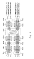
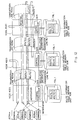
- Figure 9 shows an example in which a congested state occurrs in the packet transmission unit of the transmission line accommodating unit 501 which accommodates transmission line 403 DC connected to node 402 C .
- a congestion detected information is transmitted through the control bus 508 to the control processor 505 (see Figure 5) of node 402 C . Then, the control processor 505 allows the common channel signaling unit 507 to transmit regulation information indicating that the congestion occurred in transmission line 403 DC to the common channel. Thus, the regulation information is transmitted to all other nodes 402 A , 402 B and 403 D to the packet communication network 401 of Figure 4.
- the control processor 505 ( Figure 5) of each node looks up the table corresponding to transmission line 403 DC of the route information table TBL1 stored in the route information table memory unit 506 of Figure 5 to thereby extract information indicating route 3 and route 4, as shown in Figure 7. Then, the control processor 505 determines on the basis of a call control table (not shown) or the like whether or not the route of the corresponding route number is involved in the transmission line accommodated within its own node.
- control processor 505 raises the flag "1" indicating "regulation” in the address corresponding to the above-mentioned route of the regulation route table memory unit 604 (see Figure 6) within the transmission line interface unit 501 accommodating the transmission line 403 via the control bus 508.
- the control processor 505 of node 402 B receives the regulation information concerning transmission line 403 DC from node 402 C , the control processor 506 extracts route 3 and route 4 from the route information table TBL1 as shown in Figure 9. Having determined that routes 3 and 4 are included in its own node, the control processor 505 raises the flag "1" indicating "regulation” in the addresses corresponding to routes 3 and 4 of the regulation route table TBL2 stored in the regulation route table memory unit 604 within the transmission line interface unit 501 accommodating the transmission line 403 BC which includes routes 3 and 4, as shown in Figure 8B.
- control processor 505 raises the flag "1 " indicating "regulation” in the address corresponding to route 3 of the regulation route table TBL2 stored in the regulation route memory unit 604 provided within the transmission line interface unit 501 accommodating the transmission line 403 AB which includes route 3, as shown in Figure 8A.
- the packet data transferred on the transmission line is composed of an information field in which communication data is stored, a header in which address information is stored and a route number region in which route number 611 indicating the route through which packet data is transmitted is stored. This route number region may be included in the header.
- the route number extracting unit 602 ( Figure 6) provided within the transmission line interface unit 501 which accommodates transmission line 403 BC connected to node 402 B , the route number 611 stored in the route number region of the packet data input to the input and output unit 601 ( Figure 6) from the packet highway 506 through the distribution unit 504 ( Figure 5) is extracted. If this extracted route number 611 indicates, for example, route 2, the regulation route flag 612 of "0" indicating "pass” is output to the selector 605 (see Figure 8B). Thus, the selector 605 connects the corresponding packet data to the pass route queue of the pass route queue buffer 607. However, the gate control unit 609 generally controls the gate 610 so as to select the output of the pass route queue buffer 607, as earlier noted. Therefore, the packet data indicating route 2 is normally transferred via transmission line 403 BC .
- the route number 611 indicates, for example, route 3 or route 4
- the regulation route flag 612 of "1" indicating "regulation” is output to the selector 605 (see Figure 8B).
- the selector 605 connects the corresponding packet data to the regulation route queue of the regulation route queuing buffer 606.
- the selector 605 since the selector 605 normally permits the gate 610 to select the output of the pass route queuing buffer 607 as mentioned before, the packet data indicating route 3 or route 4 connected to the regulation route queue is not transmitted to transmission line 403, but is restricted in the node 402 B of Figure 9 as shown by the arrow.
- the packet data is input from the input and output unit 601 ( Figure 6) to the transmission line interface unit 501 which accommodates transmission line 403 AB of node 402 A and the route number 611 extracted by the route number extracting unit 602 indicates, for example, route 1 or route 2, then the regulation route flag 612 of "0" indicating "pass” is output to the selector 605 (see Figure 8A).
- the selector 605 connects the corresponding packet data to the pass route queue of the pass route queuing buffer 607, whereby packet data indicating routes 1 and 2 are normally transferred via transmission line 403 AB .
- the route number 611 indicates, for example, route 3
- the regulation route flag 612 of "1" indicating "regulation” is output to the selector 605 (see Figure 8A).
- the selector 605 connects the corresponding packet data to the regulation route queue of the regulation route queuing buffer 606, whereby the packet data indicating route 3 is not transmitted to transmission line 403 AB and the output is regulated as shown by the arrow of node 402 A of Figure 9.
- the packet data of routes 3 and 4 flowed to transmission line 403 DC can be readily regulated and the regulation queuing buffer 606 of Figure 6 can be prevented from being overflowed so that the congested state at the exit to transmission line 403 DC in node 402 C can be readily dissolved.
- transmission lines 403 AB and 403 BC only the packet data of route 3 and route 4 passing through transmission line 403 DC are regulated.
- the packet data of route 1 and route 2 are not regulated, but are transferred in an ordinary fashion. Accordingly, the congested state in transmission line 403 DC can be suppressed from spreading to other transmission lines.
- the stored amount supervisory unit 613 within the transmission line interface unit 501 transmits information indicating that the congested state in transmission line 403 DC is dissolved through the control bus 508 to the control processor 505 5 ).
- the control processor 505 transmits the same information indicating that the congested state in the transmission line 403 DC is cancelled through the common channel signaling unit 507 to the common channel 509.
- this information is transmitted to all other nodes 402 A , 402 B and 402 D of the packet communication network 401 of Figure 4.
- the control processor 505 of each node looks up the table corresponding to transmission line 403 DC of the route information table TBL1 stored in the route information table memory unit 506 of Figure 5. The information indicating routes 3 and 4 is thereby extracted, as shown in Figure 7. Then, the control processor 505 determines whether or not the route with the corresponding route number is included in its own node. If it is, the control processor 505 transmits congestion cancel information through the control bus 508 to the gate control unit 609 provided within the transmission line interface unit 501 accommodating transmission line 403, which includes that route.
- the gate control unit 609 permits the gate 610 to select the output of the regulation route queuing buffer 606 to thereby transmit the packet data connected to the regulation route queue of the regulation route queuing buffer 606 to the transmission line 403. Then, the gate control unit 609 permits the gate 610 to select the output of the pass route queuing buffer 607 again.
- control processor 505 releases the flag "1" indicating "regulation” from the address corresponding to the route of the regulation route table memory unit 604 (see Figure 6) provided within the above-mentioned transmission line interface unit 501, and raises the flag "0" indicating "pass” in this address.
- the first embodiment of the present invention is compared with the example of the prior art shown in Figure 2 as follows.
- the congested state occurs in the transmission line 403' including one node 402'
- all transmission lines concerning with communication lines including the node 402' are regulated as shown by the hatched portions of Figure 2.
- the congestion state will spread to other nodes or other transmission lines.
- traffic passing through the transmission line is classified into "routes" and grouped, whereby congestion supervised objects can be limited to far fewer kinds of routes than in the prior art in which several hundreds to several thousands of individual communications must be supervised.
- This embodiment relates to the direct regulation system in which regulation information is directly transmitted to an input source of traffic which causes congestion.
- the entire arrangement of the packet communication network, the block diagram of the packet-switching node and the arrangement of the route information table TBL1 are similar to those of the first embodiment of Figures 4, 5 and 7.
- the arrangement of the transmission line interface unit 501 of Figure 5 is different from that of the first embodiment in that the route number extracting unit 602, the regulation route table memory unit 604, the selector 605 and the regulation queuing buffer 606 shown in Figure 6 are not provided.
- packet data input from the input and output unit 601 is directly connected to the pass route queue of the pass route queuing buffer 607.
- the format of packet data transmitted on the transmission line may be an ordinary one which does not need the route number region shown in Figure 10.
- the information of congestion detection is transmitted to the control processor 505 (see Figure 5) of node 402 C through the control bus 508, and the control processor 505 transmits the regulation information indicating that congestion has occurred in transmission line 403 DC from the common channel signaling unit 507 to the common channel 509.
- the regulation information is issued or transmitted to nodes 402 A , 402 B and 402 D accommodating the terminal 404 (see Figure 4) of the packet communication network 401 of Figure 4.
- the aforementioned route regulation operation is executed in each of nodes 402 B and 402 A on the basis of the route information table memory unit 506 of Figure 5 and the regulation route table memory unit 604 of Figure 6.
- the respective control processor 505 of nodes 402 A and 402 B extracts route 3 and route 4 from the route information table TBL1 on the route information memory unit 506 (both seen in Figure 5) as shown in Figure 12 are similar to those of the first embodiment of Figure 9.
- the output regulation is not sequentially performed by the transmission line interface unit 501 of the output side of the upstream node.
- Nodes 402 A and 402 B determine whether or not the terminals 404 using routes 3 and 4 are included in their own nodes. In that event, the respective nodes administer routes which are utilized by the terminals 404 accommodated by their own nodes, and such administration is performed as the ordinary control operation in the packet-switching node.
- the control processor 505 of Figure 5 executes the direct input regulation onto the packet assembly/disassembly unit 502 and terminals 404 A2 and 404 A4 connected thereto through the packet assembly/disassembly unit 502.
- This direct input regulation is realized by outputting a busy signal to, for example, terminals.
- the input regulation is not executed on a terminal which does not utilize its corresponding terminal.
- the respective nodes need not grasp all communications concerning their own nodes, but may grasp only the state of the transmission line which is accommodated by the corresponding node via the stored amount supervisory unit 608 (see Figure 6) corresponding to that transmission line, thereby efficting efficient transmission of regulation information by using only information of the transmission line. Then, each node can perform proper regulation control by utilizing the route information table TBL1 in units of "route".
- input regulation can be directly and effectively executed on the terminals which participate in the communication passing the congested transmission line.
- This embodiment relates to the direct regulation system in which direct regulation information is issued or transmitted to the input source, as in the second embodiment.
- the overall arrangement of the packet communication network is similar to that of the first embodiment of Figure 4, and the arrangement of the route information table TBL1 in the packet-switching node is similar to that of the first embodiment of Figure 7.
- the arrangement of the transmission line interface unit 501 (see Figure 5) is similar to that of the second embodiment, and in addition, the format of the packet transferred on the transmission line may be ordinary one and needs no route number region as shown in Figure 10.
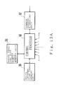
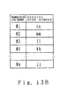
- This embodiment includes as the arrangement of the packet-switching node a block arrangement shown in Figure 13A in addition to the arrangement of Figure 4. More specifically, in addition to the route information table memory unit 506, which is one of the specific features of the first embodiment, the third embodiment includes a route sending node number table memory unit 1301. Furthermore, a route sending node number table as shown in Figure 13 is stored in this route sending node number table memory unit 1301. This route sending node number table can retrieve packet-switching nodes which become the starting points of the routes corresponding to the route numbers, i.e., sending node numbers nn, mm, ll, kk, . to #n accommodated within the transmission lines of its own node. This table is fixedly set when the circuit is set. In this embodiment, the following controls are executed by using this sending node number table.
- the congestion detection information is transmitted to the control processor 505 (see Figure 5) of node 402 C through the control bus 508.
- the control processor 505 When receiving the congestion detection information, the control processor 505 looks up the sending node number table memory unit 1301 of Figure 13A to retrieve the sending node numbers of routes 3 and 4 accommodated in transmission line 403 DC in which the congestion occurs, from the sending node number table of Figure 13B. Then, the control processor 505 transmits the regulation information indicating that congestion has occurred in transmission line 403 DC , to the packet-switching node of the retrieved sending number from the common channel signaling unit 507 through the common channel 509.
- This operation causes the direct regulation information to be transmitted to node 402 A which is the sending node for route 3.
- node 402 A carries out exactly the same control operation as the second embodiment. More specifically, when the control processor 505 ( Figure 5) of node 402 A receives the regulation information on transmission line 403 DC , it extracts route 3 from the route information table TBL1 on the route information table memory unit 506 of Figure 5. Further, it determines on the basis of the inside administration information that, as shown, for example, in Figure 12, route 3 is occupied by terminals 404 A2 and 404 A4 . Thus, the control processor 505 executes the input regulation on the packet assembly/disassembly unit 502 and terminals 404 A2 and 404 A4 connected through the packet assembly/disassembly unit 502.
- the input regulation is directly and effectively executed on the terminals which participate in the communication passing through the congested transmission line.
- the input regulation is readily extended onto only the sending node of the corresponding route, and the redundant regulation information packet can be prevented from being transferred to another node. Therefore, the regulation information can be executed efficiently and the congestion can be readily cancelled.
- the overall arrangement of the packet communication network is similar to that of the first embodiment of Figure 4.
- the route information table memory unit 506 shown in Figure 5 is not needed.
- the per-route sending node number table memory unit 1301 may be provided.
- the route number extracting unit 602 when the output regulation is carried out by using the regulation route table TBL2, as in the first embodiment, the route number extracting unit 602, the regulation route table memory unit 604, the selector 605 and the regulation route queuing buffer 606 are provided as shown in Figure 6. Conversely, when the output regulation is not carried out as shown in the second or third embodiment, these units are not provided.
- a circuit block arrangement shown in Figure 14 is additionally connected to the output side of the pass route queuing buffer 607 as the feature of the present embodiment.
- each node when the control processor 505 ( Figure 5) of each node receives information of a call setting (communication start of each communication) to a certain route from other node through the common channel signaling unit 507 from the common channel 509, the control processor 505 outputs an average traffic amount of routes included in the above-mentioned information through the control bus 508 to the transmission line interface unit 501 (see Figure 5) which accommodates the transmission line corresponding to that route.
- This average traffic amount is determined on the basis of a user's statement when the call is set.
- the information of the average traffic amount is received by a control unit 1403 of Figure 14 and stored in a flow table memory unit 1602 of Figure 14, together with the route number.
- a flow supervisory unit 1401 watches the flow of each route at the output unit of the pass route queuing buffer 607. To this end, the packet data transmitted on the transmission line is provided with the route number region in which the route number is stored, as in Figure 10 of the first embodiment. Then, the flow supervisory unit 1401 extracts the route number from the route number region of the packet data output from the pass route queuing buffer 607 and supervises the flow of each route by counting the number of packet data at a predetermined time interval (e.g. 100 milliseconds) for every route identified by the route number.
- a predetermined time interval e.g. 100 milliseconds
- control unit 1403 compares the flow of every route output from the flow supervisory unit 1401 with the average traffic amount of the route stored in the flow table memory unit 1402, and determines the occurrence of congestion when the flow exceeds the average traffic amount.
- control unit 1403 cannot determine whether or not congestion occurrs this route. This judgment is executed when the control unit 1403 of Figure 14 accesses the stored amount supervisory unit 608 of Figure 6.
- the control unit 1403 of Figure 14 transmits the congestion detection information to the control processor 505 (see Figure 5) via the control bus 508. Then, the control processor 505 transmits the regulation information indicating that congestion has occurred in the corresponding route to the common channel 509 from the common channel signaling unit 507. Thus, the regulation information is transmitted to another node 402 (see Figure 4).
- the node since the regulation information is directly issued by using the route number as described above, the node, when receiving this regulation information, need not refer to the route information table TBL1 as shown in the first to third embodiments. Thereafter, as in the first embodiment, the output regulation may be carried out at the output side transmission line interface unit 501 by using the regulation route table TBL2 or the like. Alternatively, as in the second and third embodiments, the direct input regulation may be executed on the terminal which utilizes the regulation informed route by the terminal which is accommodated by its own node.
- the regulation information when the regulation information is transmitted, not the transmission line information in the first to third embodiments but the information concerning the route is directly transmitted. Accordingly, the information amount in the regulation information is greater than in the first to third embodiments in which the transmission line information is transmitted.
- the information amount can be considerably reduced compared with the prior art.
- the node which receives the regulation information need not perform processing for judging the route from the information of the transmission line. Thus, the regulation control operation can be simplified compared with the first to third embodiments.
Description
Claims (12)
- A packet transfer regulating apparatus for regulating packet transfer in a packet communication network (401) composed of:
- (i)
- transmission lines (403) for interconnecting a plurality of packet-switching nodes (402), and
- (ii)
- a plurality of terminals (404) connected to said packet-switching nodes (402);
controlling means (301-305,309-311) provided in each of said packet-switching nodes (402) for controlling a congested state of at least one (308, 313) of a plurality of routes, each of which routes can be uniquely discriminated and is defined by arbitrarily selecting at least one of said packet-switching nodes and at least one of said transmission lines in said packet communication network in an arbitrary order such that the packet-switching nodes and the transmission lines thus selected are connected alternately together;each of said controlling means being adapted to control the congested state only of those routes in the packet communication network which pass through the one of said packet-switching nodes respectively containing said controlling means. - A packet transfer regulating apparatus according to claim 1, wherein said controlling means (301-305,309-311) provided in each of said packet-switching nodes includes:route memory means (301) for memorizing which of said plurality of routes is defined by selecting each of said transmission lines in said packet communication network;congested state detecting means (302) for detecting a congested state of at least one (306) of those of said transmission lines connected to the one of the packet-switching nodes respectively containing said congested state detecting means;congested state informing means (303) for transmitting information (307) identifying said transmission line congested state detected by said congested state detecting means (302) to at least another one of the packet-switching nodes as congested state information;route identifying means (304) for receiving said congested state information (307) from at least another one of the packet-switching nodes and for retrieving from said route memory means (301) information identifying those of said routes defined by selecting said one (306) of those of said transmission lines corresponding to said congested state information thus received, to thereby identify those (308) of said routes thus retrieved defined by selecting the one of said packet-switching nodes respectively containing said route identifying means; androute control means (305) for controlling a congested state of those (308) of said routes thus identified by said route identifying means (304) on the basis of said congested state information (307) thus received.
- A packet transfer regulating apparatus according to claim 2, wherein:said congested state detecting means (302) detects either an occurrence of said congested state or a cancellation of said congested state of said one (306) of those of said transmission lines connected to the one of said packet-switching nodes respectively containing said congested state detecting means;said congested state information is either
- (i)
- congested state occurrence information indicating that said congested state has occurred in said one (306) of those of said transmission lines connected to the one of said packet-switching nodes respectively containing said congested state detecting means, or
- (ii)
- congested state cancellation information indicating that said congested state occurring in said one (306) of those of said transmission lines connected to the one of said packet-switching nodes respectively containing said congested state detecting means is cancelled; and
- (i)
- regulating transmission of packet data transferred through said routes (308) identified by said route identifying means (304) when receiving said congested state occurrence information from said other one of the packet-switching nodes, and for
- (ii)
- cancelling said regulating in said routes (308) identified by said route identifying means (304) when receiving said congested state cancellation information from said other one of the packet-switching nodes.
- A packet transfer regulating apparatus according to claim 3, wherein each of said packet-switching nodes further comprises:transmission queuing buffer means (607) at every one of said transmission lines (403) connected to the one of said packet-switching nodes respectively containing said transmission queuing buffer means for holding packet data to be transmitted to the respective ones of said transmission lines at each of said transmission queuing buffer means; andregulation queuing buffer means (606) at every one of said transmission lines (403) connected to the one of said packet-switching nodes respectively containing said regulation queuing buffer means for holding packet data whose transmission to the respective ones of said transmission lines at each of said regulation buffer means is to be regulated;and wherein:a one of said congested state detecting means (302) is provided at every one of said transmission lines connected to the one of said packet-switching nodes respectively containing said congested state detecting means, and said congested state detecting means (302) supervises an amount of packet data stored in the respective one of said transmission queuing buffer means (607), to thereby detect either the occurrence of said congested state or the cancellation of said congested state of the respective transmission line;a one of said route control means (305) is provided at every one of said transmission lines connected to the one of said packet-switching nodes respectively containing said route control means; andsaid route control means (305) is comprised of:
- (i)
- regulation route memory means (604) for memorizing:
- (a)
- information indicating whether or not the transmission of packet data is presently regulated on every route defined by selecting the respective one of said transmission lines at which said route control means is provided, and
- (b)
- when receiving said congested state occurrence information from said other one of the packet-switching nodes, information indicating that said routes (308) identified by said route identifying means (304) are regulated, while when receiving said congested state cancellation information from said other one of the packet-switching nodes, information indicating that said regulation to said routes (308) identified by said route identifying means (304) is cancelled;
- (ii)
- route extracting means (602) for extracting a route from packet data to be transmitted to the respective one of said transmission lines at which said route control means is provided;
- (iii)
- selector means (605) for determining on the basis of the contents of said regulation route memory means (604) whether or not said regulation is to be executed on said route extracted by said route extracting means (602), wherein when said regulation is to be executed, said selector means (605) allows said regulation queuing buffer means (606) to hold the packet data to be transmitted, and when said regulation is not to be executed, said selector means (605) allows said transmission queuing buffer means (607) to hold the packet data to be transmitted; and
- (iv)
- gate means (610) for transmitting the packet data held in said regulation queuing buffer means (606) to the respective one of said transmission lines at which said route control means is provided when receiving said congested state cancellation information from said other one of the packet-switching nodes, and for transmitting the packet data held in said transmission queuing buffer means (607) to the respective one of said transmission lines at which said route control means is provided in other cases.
- A packet transfer regulating apparatus according to claim 4, wherein a route number (611) indicating which one of the routes through which said packet data is to be transmitted is added to said packet data, and said route extracting means (602) extracts said one of the routes from the packet data to be transmitted to the one of said packet-switching nodes respectively containing said route extracting means by judging said route number added to said packet data.
- A packet transfer regulating apparatus according to claim 4, wherein said route control means (305) is provided at every one of a plurality of transmission line interface units (501) which are connected to respective ones of said transmission lines connected to the one of said packet-switching nodes respectively containing said route control means.
- A packet transfer regulating apparatus according to claim 2, wherein said route control means (305) :determines whether or not those terminals utilizing said routes (308) identified by said route identifying means (304) are connected to the one of said packet-switching nodes respectively containing said route control means, andperforms regulation of the input of packet data transmitted by said terminals thus connected or cancellation of said input regulation on the basis of said congested state information (307) received.
- A packet transfer regulating apparatus according to claim 7, wherein each of said packet-switching nodes further comprises:and wherein:per route sending node identifying information memory means (1301) for storing, for every route defined by selecting a one of said transmission lines connected to the one of said packet-switching nodes respectively containing said per route sending node identifying information memory means, information identifying a sending one of said packet-switching nodes which is a starting point of a one of said routes;said congested state informing means (303) searches for the one of said sending ones of said packet-switching nodes corresponding to the one of said routes defined by selecting the one of said transmission lines for which said congested state detecting means (302) detects said congested state by referring to the per route sending node identifying information memory means (1301).
- A packet transfer regulating apparatus according to claim 8, wherein contents of said route memory means (301) and of said per route sending node identifying information memory means (1301) are set in response to the layout of respective circuits of said packet communication network.
- A packet transfer regulating apparatus according to claim 1, wherein said controlling means (301-305, 309-311) provided in each of said packet-switching nodes includes:congested state detecting means (309) for detecting a congested state of at least one (313) of those of said routes defined by selecting those of said transmission lines connected to the one of said packet switching nodes respectively containing said congested state detecting means;congested state informing means (310) for transmitting information (312) identifying said route congested state detected by said congested state detecting means (309) to at least another one of the packet-switching nodes as congested state information; androute control means (311) for receiving said congested state information (312) from at least another one of the packet-switching nodes and controlling a congested state of those of said routes defined by selecting the one of said packet-switching nodes respectively containing said route control means, when said routes thus defined are in the route corresponding to said congested state information (312).
- A packet transfer regulating apparatus according to claim 10, wherein said congested state detecting means (309) is comprised of:flow supervising means (1401) for supervising a flow of packet data in said one (313) of those of said routes defined by selecting the one of said transmission lines connected to the one of said packet-switching nodes respectively containing said congested state detecting means, anddetecting means (1403) for detecting said congested state of said one (313) of said routes by comparing the flow of packet data supervised by said flow supervising means (1401) with a traffic amount set when a call-setting in said one (313) of said routes is performed.
- A packet transfer regulating apparatus according to claim 11, wherein a route number (611) indicating which one of the routes through which said packet data is to be transmitted is additionally provided in said packet data and said flow supervising means (1401):judges said route number added to said packet data in the one of said transmission lines connected to the one of said packet-switching nodes respectively containing said congested state detecting means, andsupervises the flow on each of said routes identified by said route number (611) by counting the number of packets at predetermined time intervals.
Applications Claiming Priority (4)
| Application Number | Priority Date | Filing Date | Title |
|---|---|---|---|
| JP6683890A JP2785147B2 (en) | 1990-03-19 | 1990-03-19 | Restriction method for each route |
| JP2068150A JPH03270439A (en) | 1990-03-20 | 1990-03-20 | Regulating system fur every route |
| JP68150/90 | 1990-03-20 | ||
| JP66838/90 | 1991-03-19 |
Publications (3)
| Publication Number | Publication Date |
|---|---|
| EP0448049A2 EP0448049A2 (en) | 1991-09-25 |
| EP0448049A3 EP0448049A3 (en) | 1993-08-18 |
| EP0448049B1 true EP0448049B1 (en) | 1998-08-12 |
Family
ID=26408039
Family Applications (1)
| Application Number | Title | Priority Date | Filing Date |
|---|---|---|---|
| EP91104248A Expired - Lifetime EP0448049B1 (en) | 1990-03-19 | 1991-03-19 | Packet transfer regulating apparatus |
Country Status (4)
| Country | Link |
|---|---|
| US (1) | US5309431A (en) |
| EP (1) | EP0448049B1 (en) |
| CA (1) | CA2038458C (en) |
| DE (1) | DE69129952T2 (en) |
Families Citing this family (20)
| Publication number | Priority date | Publication date | Assignee | Title |
|---|---|---|---|---|
| JPH0556490A (en) * | 1991-08-28 | 1993-03-05 | Fujitsu Ltd | Congestion control system between pbx and atm multiplex transmitter |
| US5742760A (en) * | 1992-05-12 | 1998-04-21 | Compaq Computer Corporation | Network packet switch using shared memory for repeating and bridging packets at media rate |
| US6192413B1 (en) * | 1992-07-30 | 2001-02-20 | International Business Machines Corporation | Method and system for process queue communications routing |
| JP3187230B2 (en) * | 1993-09-06 | 2001-07-11 | 株式会社東芝 | Congestion control method and congestion control device |
| US5509123A (en) * | 1994-03-22 | 1996-04-16 | Cabletron Systems, Inc. | Distributed autonomous object architectures for network layer routing |
| AU710270B2 (en) * | 1994-07-25 | 1999-09-16 | Telstra Corporation Limited | A method for controlling congestion in a telecommunications network |
| US5515359A (en) * | 1994-08-26 | 1996-05-07 | Mitsubishi Electric Research Laboratories, Inc. | Credit enhanced proportional rate control system |
| FI97185C (en) * | 1994-11-11 | 1996-10-25 | Nokia Telecommunications Oy | Overload lock in a node in a data communication network |
| FI97186C (en) * | 1994-11-11 | 1996-10-25 | Nokia Telecommunications Oy | Overload lock in a node in a data communication network |
| AU6501496A (en) * | 1995-07-19 | 1997-02-18 | Ascom Nexion Inc. | Point-to-multipoint transmission using subqueues |
| AUPN526595A0 (en) | 1995-09-07 | 1995-09-28 | Ericsson Australia Pty Ltd | Controlling traffic congestion in intelligent electronic networks |
| JPH11512583A (en) | 1995-09-14 | 1999-10-26 | フジツウ ネットワーク コミュニケーションズ,インコーポレイテッド | Transmitter-controlled flow control for buffer allocation in a wide area ATM network |
| US5777987A (en) * | 1995-12-29 | 1998-07-07 | Symbios, Inc. | Method and apparatus for using multiple FIFOs to improve flow control and routing in a communications receiver |
| JP2000517488A (en) | 1996-01-16 | 2000-12-26 | フジツウ ネットワーク コミュニケーションズ,インコーポレイテッド | Reliable and flexible multicast mechanism for ATM networks |
| US5748905A (en) * | 1996-08-30 | 1998-05-05 | Fujitsu Network Communications, Inc. | Frame classification using classification keys |
| JP3518209B2 (en) * | 1996-12-05 | 2004-04-12 | 株式会社日立製作所 | ATM exchange and congestion control method |
| JP3251537B2 (en) * | 1997-06-16 | 2002-01-28 | 矢崎総業株式会社 | Communication method and communication system |
| US6954429B2 (en) * | 2000-04-05 | 2005-10-11 | Dyband Corporation | Bandwidth control system |
| US7209447B1 (en) * | 2000-07-13 | 2007-04-24 | Tellabs Operations, Inc. | Method and apparatus for measuring packet connection quality of service |
| US7295516B1 (en) * | 2001-11-13 | 2007-11-13 | Verizon Services Corp. | Early traffic regulation techniques to protect against network flooding |
Family Cites Families (7)
| Publication number | Priority date | Publication date | Assignee | Title |
|---|---|---|---|---|
| FR2616024B1 (en) * | 1987-05-26 | 1989-07-21 | Quinquis Jean Paul | SYSTEM AND METHOD FOR PACKET FLOW CONTROL |
| JPS6467046A (en) * | 1987-09-08 | 1989-03-13 | Ricoh Kk | Multiplex repeating installation device for variable communication network |
| JP2540930B2 (en) * | 1988-02-19 | 1996-10-09 | 日本電気株式会社 | Congestion control device |
| JPH01221042A (en) * | 1988-02-29 | 1989-09-04 | Toshiba Corp | Congestion control method for packet exchange |
| NL8901171A (en) * | 1989-05-10 | 1990-12-03 | At & T & Philips Telecomm | METHOD FOR MERGING TWO DATA CELL FLOWS TO ONE DATA CELL FLOW, AND ATD MULTIPLEXER FOR APPLICATION OF THIS METHOD |
| US5107493A (en) * | 1989-08-02 | 1992-04-21 | At&T Bell Laboratories | High-speed packet data network using serially connected packet and circuit switches |
| US5014265A (en) * | 1989-11-30 | 1991-05-07 | At&T Bell Laboratories | Method and apparatus for congestion control in a data network |
-
1991
- 1991-03-18 CA CA002038458A patent/CA2038458C/en not_active Expired - Fee Related
- 1991-03-19 EP EP91104248A patent/EP0448049B1/en not_active Expired - Lifetime
- 1991-03-19 US US07/671,959 patent/US5309431A/en not_active Expired - Lifetime
- 1991-03-19 DE DE69129952T patent/DE69129952T2/en not_active Expired - Lifetime
Non-Patent Citations (1)
| Title |
|---|
| MONITORING ALGORITHM FOR ATM NETWORKS' * |
Also Published As
| Publication number | Publication date |
|---|---|
| DE69129952T2 (en) | 1999-02-11 |
| CA2038458C (en) | 1999-01-26 |
| EP0448049A3 (en) | 1993-08-18 |
| EP0448049A2 (en) | 1991-09-25 |
| CA2038458A1 (en) | 1991-09-20 |
| DE69129952D1 (en) | 1998-09-17 |
| US5309431A (en) | 1994-05-03 |
Similar Documents
| Publication | Publication Date | Title |
|---|---|---|
| EP0448049B1 (en) | Packet transfer regulating apparatus | |
| EP0291079B1 (en) | Apparatus for controlling packet switched networks | |
| US7532570B2 (en) | Fault tolerant network traffic management | |
| US7075889B2 (en) | Packet protection technique | |
| JP2728118B2 (en) | Communication system for load balancing and load balancing | |
| JPH07202942A (en) | Packet switchboard | |
| JPH0831876B2 (en) | Routing control method in packet switching network | |
| JP2001292164A (en) | Packet switch and its switching method | |
| US6278690B1 (en) | Local area network for reconfiguration in the event of line ruptures or node failure | |
| US5787073A (en) | ATM cell rate control with transmission priority given to control cells for quick response to network congestion | |
| US6553035B1 (en) | Apparatus and method for queuing data | |
| JP2535874B2 (en) | Routing control method for packet switching network | |
| JP2003092593A (en) | Node with routing controlling function with congestion control taken into consideration and routing control system in network adopting the node | |
| JPH05160851A (en) | Electronic exchange method for asynchronous transfer mode communication system | |
| JPH04100343A (en) | Atm link system | |
| JP2785147B2 (en) | Restriction method for each route | |
| JP2000224180A (en) | Data priority transfer method | |
| JP2616431B2 (en) | Packet communication system and apparatus for load balancing | |
| JP3250546B2 (en) | Packet switching device, multicast control method used therefor, and recording medium recording control program therefor | |
| JPH01303832A (en) | Routing control system | |
| JP2560270B2 (en) | Input traffic distribution control system | |
| JP2662258B2 (en) | Information relay node device | |
| JPH04168835A (en) | Routing system for atm exchange and routing system for atm exchange network | |
| JP3174122B2 (en) | Packet switching equipment | |
| JP3636086B2 (en) | Congestion detection device |
Legal Events
| Date | Code | Title | Description |
|---|---|---|---|
| PUAI | Public reference made under article 153(3) epc to a published international application that has entered the european phase |
Free format text: ORIGINAL CODE: 0009012 |
|
| AK | Designated contracting states |
Kind code of ref document: A2 Designated state(s): DE FR GB |
|
| PUAL | Search report despatched |
Free format text: ORIGINAL CODE: 0009013 |
|
| AK | Designated contracting states |
Kind code of ref document: A3 Designated state(s): DE FR GB |
|
| 17P | Request for examination filed |
Effective date: 19931229 |
|
| 17Q | First examination report despatched |
Effective date: 19960822 |
|
| GRAG | Despatch of communication of intention to grant |
Free format text: ORIGINAL CODE: EPIDOS AGRA |
|
| GRAG | Despatch of communication of intention to grant |
Free format text: ORIGINAL CODE: EPIDOS AGRA |
|
| GRAH | Despatch of communication of intention to grant a patent |
Free format text: ORIGINAL CODE: EPIDOS IGRA |
|
| GRAH | Despatch of communication of intention to grant a patent |
Free format text: ORIGINAL CODE: EPIDOS IGRA |
|
| GRAA | (expected) grant |
Free format text: ORIGINAL CODE: 0009210 |
|
| AK | Designated contracting states |
Kind code of ref document: B1 Designated state(s): DE FR GB |
|
| REF | Corresponds to: |
Ref document number: 69129952 Country of ref document: DE Date of ref document: 19980917 |
|
| ET | Fr: translation filed | ||
| PLBE | No opposition filed within time limit |
Free format text: ORIGINAL CODE: 0009261 |
|
| STAA | Information on the status of an ep patent application or granted ep patent |
Free format text: STATUS: NO OPPOSITION FILED WITHIN TIME LIMIT |
|
| 26N | No opposition filed | ||
| REG | Reference to a national code |
Ref country code: GB Ref legal event code: IF02 |
|
| REG | Reference to a national code |
Ref country code: GB Ref legal event code: 732E |
|
| REG | Reference to a national code |
Ref country code: FR Ref legal event code: TP |
|
| PGFP | Annual fee paid to national office [announced via postgrant information from national office to epo] |
Ref country code: FR Payment date: 20100318 Year of fee payment: 20 |
|
| PGFP | Annual fee paid to national office [announced via postgrant information from national office to epo] |
Ref country code: GB Payment date: 20100208 Year of fee payment: 20 |
|
| PGFP | Annual fee paid to national office [announced via postgrant information from national office to epo] |
Ref country code: DE Payment date: 20100331 Year of fee payment: 20 |
|
| REG | Reference to a national code |
Ref country code: DE Ref legal event code: R071 Ref document number: 69129952 Country of ref document: DE |
|
| REG | Reference to a national code |
Ref country code: GB Ref legal event code: PE20 Expiry date: 20110318 |
|
| PG25 | Lapsed in a contracting state [announced via postgrant information from national office to epo] |
Ref country code: GB Free format text: LAPSE BECAUSE OF EXPIRATION OF PROTECTION Effective date: 20110318 |
|
| PG25 | Lapsed in a contracting state [announced via postgrant information from national office to epo] |
Ref country code: DE Free format text: LAPSE BECAUSE OF EXPIRATION OF PROTECTION Effective date: 20110319 |