EP0448015B1 - Mobile radio communication system - Google Patents
Mobile radio communication system Download PDFInfo
- Publication number
- EP0448015B1 EP0448015B1 EP91104154A EP91104154A EP0448015B1 EP 0448015 B1 EP0448015 B1 EP 0448015B1 EP 91104154 A EP91104154 A EP 91104154A EP 91104154 A EP91104154 A EP 91104154A EP 0448015 B1 EP0448015 B1 EP 0448015B1
- Authority
- EP
- European Patent Office
- Prior art keywords
- mobile station
- signal
- base station
- station
- mobile
- Prior art date
- Legal status (The legal status is an assumption and is not a legal conclusion. Google has not performed a legal analysis and makes no representation as to the accuracy of the status listed.)
- Expired - Lifetime
Links
- 238000004891 communication Methods 0.000 title claims description 75
- 238000000034 method Methods 0.000 claims description 9
- 238000012544 monitoring process Methods 0.000 claims description 9
- 238000012937 correction Methods 0.000 claims description 8
- 230000006866 deterioration Effects 0.000 claims description 4
- 239000000969 carrier Substances 0.000 claims description 3
- 238000010586 diagram Methods 0.000 description 8
- 230000005540 biological transmission Effects 0.000 description 3
- 238000001514 detection method Methods 0.000 description 3
- 238000001303 quality assessment method Methods 0.000 description 3
- 238000010276 construction Methods 0.000 description 2
- 230000007423 decrease Effects 0.000 description 1
- 230000001419 dependent effect Effects 0.000 description 1
- 238000012986 modification Methods 0.000 description 1
- 230000004048 modification Effects 0.000 description 1
- 230000005236 sound signal Effects 0.000 description 1
- 238000012546 transfer Methods 0.000 description 1
Images


Classifications
-
- H—ELECTRICITY
- H04—ELECTRIC COMMUNICATION TECHNIQUE
- H04W—WIRELESS COMMUNICATION NETWORKS
- H04W36/00—Hand-off or reselection arrangements
- H04W36/0005—Control or signalling for completing the hand-off
- H04W36/0055—Transmission or use of information for re-establishing the radio link
- H04W36/0072—Transmission or use of information for re-establishing the radio link of resource information of target access point
-
- H—ELECTRICITY
- H04—ELECTRIC COMMUNICATION TECHNIQUE
- H04B—TRANSMISSION
- H04B7/00—Radio transmission systems, i.e. using radiation field
- H04B7/24—Radio transmission systems, i.e. using radiation field for communication between two or more posts
- H04B7/26—Radio transmission systems, i.e. using radiation field for communication between two or more posts at least one of which is mobile
- H04B7/2643—Radio transmission systems, i.e. using radiation field for communication between two or more posts at least one of which is mobile using time-division multiple access [TDMA]
-
- H—ELECTRICITY
- H04—ELECTRIC COMMUNICATION TECHNIQUE
- H04L—TRANSMISSION OF DIGITAL INFORMATION, e.g. TELEGRAPHIC COMMUNICATION
- H04L1/00—Arrangements for detecting or preventing errors in the information received
- H04L1/20—Arrangements for detecting or preventing errors in the information received using signal quality detector
-
- H—ELECTRICITY
- H04—ELECTRIC COMMUNICATION TECHNIQUE
- H04W—WIRELESS COMMUNICATION NETWORKS
- H04W36/00—Hand-off or reselection arrangements
- H04W36/24—Reselection being triggered by specific parameters
- H04W36/30—Reselection being triggered by specific parameters by measured or perceived connection quality data
- H04W36/304—Reselection being triggered by specific parameters by measured or perceived connection quality data due to measured or perceived resources with higher communication quality
-
- H—ELECTRICITY
- H04—ELECTRIC COMMUNICATION TECHNIQUE
- H04W—WIRELESS COMMUNICATION NETWORKS
- H04W36/00—Hand-off or reselection arrangements
- H04W36/24—Reselection being triggered by specific parameters
- H04W36/30—Reselection being triggered by specific parameters by measured or perceived connection quality data
Definitions
- the present invention generally relates to mobile radio communication systems, and more particularly to a mobile radio communication system which employs a multi-channel access system and is applicable to a mobile telephone or the like using radio zones.
- the mobile radio communication system employs a handover control procedure which enables fast and efficient communication, so that the service and the frequency utilization efficiency are improved.
- EP-A-0 318 033 discloses a mobile radio communication system employing time-divisional multiplex access (TDMA) and comprising a control station which is provided with respect to a control zone, the control zone being made up of a plurality of radio zones; a plurality of base stations, one for each of said radio zones; and a mobile station which is movable within the control zone.
- the mobile station comprises two separate receivers, a first receiver having a mixer and a demodulator for communication with the base stations, and a second receiver also having a mixer and a demodulator for receiving control signals from all base stations.
- the second receiver additionally has a level detector for determining the signal strength of the control signals constantly received from all base stations.
- Each control signal in each base station has a flag, either 0 or 1, indicating if this base stations has a free channel (flag: 1) or not (flag: 0).
- the second receiver provided with the level detector receives the control signals from the base stations and compares the reception levels only of those base stations having free channels (indicated by flag: 1), in order to monitor if the mobile station moves from one radio zone to another radio zone. When based on the comparison of reception levels a change of the radio zone is detected, and a switching request signal is transmitted from the mobile station through a current base station to the exchange or control station, then a switch to a destination base station having a free channel is performed.
- this mobile radio communication system uses signal strength monitoring performed by a second receiver in the mobile station, for determining when the mobile station leaves a particular radio zone covered by a particular base station assigned thereto, and which new radio zone is reached by the mobile station, for performing a handover to the new base station of the new radio zone.
- each base station has to transmit a dedicated control signal containing a flag, which control signal is only used for monitoring a change of radio zones.
- Communication signals are received by the mobile station through the first receiver thereof.
- US-A-4 829 519 discloses that monitoring of signal strength and the use of signal strength monitoring to determine when a transfer from one radio zone to another radio zone is to be made, is in itself inadequate.
- this prior art document suggests that the mobile station should monitor a message transmitted from a base station, and based on this monitoring the mobile station determines a bit or symbol error rate above a threshold relating thereto, and the mobile station automatically sequentially monitors messages from adjacent base stations, such that the mobile station automatically switches from a first to a second base station the message of which has a bit or symbol error rate below threshold.
- the first kind of messages relates to "ordinary" messages which are error corrected in the mobile station for obtaining a correct message, then this corrected message is compared with the received message, and a signal quality assessment is performed based on the bit or symbol error rate.
- a second kind of messages relates to special quality assessment messages which according to the disclosure in this prior art document are preferable over ordinary messages.
- the quality assessment messages are transmitted by the base stations on every outbound channel, resulting in considerable expenditures with respect to the power required for transmissions in every outbound channel of the base stations, for example.
- a handover is made when a called base station changes from an old base station to a new base station.
- the base station of an old radio zone in which the mobile station first exists and the base stations in neighboring radio zones measure the field intensity of a signal from the mobile station.
- a radio zone of the base station which receives the signal from the mobile station with the highest field intensity is regarded as a new radio zone in which the mobile station now exists.
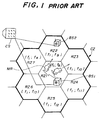
- FIG.1 shows radio zones of an existing analog mobile telephone as an example of the conventional mobile radio communication system which uses the FDMA system and employs the radio zones.
- a control zone CZ surrounded by a bold solid line includes a plurality of radio zones which are under control of a single control station CS.
- the control zone CZ includes seven radio zones RZ1 through RZ7.
- FIG.1 only shows a base station BS1 of the radio zone RZ1 and a base station BS2 of the radio zone RZ2.
- a mobile station MR exists within an arbitrary radio zone RZi within the control zone CZ.
- the mobile station MR may be a mobile telephone set equipped to an automobile or a portable telephone set which is hand carried by the user.
- FIG.2 (A) and (B) respectively show control signals for controlling call-out and call-in
- FIG.3 (A) and (B) respectively show voice signals.
- a radio line uses a control channel C-CH and a voice channel V-CH which are not time-division-multiplexed.
- C-CH control channel
- V-CH voice channel
- one control channel group f1 is assigned to one control zone CZ
- voice channel groups f8 through f14 are respectively assigned to the radio zones RZ1 through RZ7 so that the frequencies of the voice channels do not overlap among the radio zones RZ1 through RZ7 within the same control zone CZ.
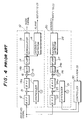
- FIG.4 shows an example of a receiving system of the base station in the conventional mobile radio communication system.
- the receiving system includes a receiver 10 for receiving a voice channel signal, a receiver 20 exclusively for measuring the field intensity of a signal from the mobile station MR for the purpose of determining the radio zone in which the mobile station MR is located, and a controller 30 for controlling synthesizers 11 and 21 of the respective receivers 10 and 20 and the channel frequency in response to an instruction from the control station CS.
- the received signal which passes through a bandpass filter 12 is mixed to a first local signal which has a frequency set by the synthesizer 11 in a mixer 13 and is converted into a signal having a first intermediate frequency.
- the output signal of the mixer 13 is passed through a bandpass filter 14a and is mixed to a second local signal which has a frequency set by a synthesizer 15 and is converted into a signal having a second intermediate frequency in a mixer 16.
- the output signal of the mixer 16 is passed through a bandpass filter 14b and is amplified by an intermediate frequency amplifier 17.
- a field intensity detector 18 detects the field intensity of the received signal based on an output signal of the intermediate frequency amplifier 17 and notifies the detected field intensity to the control station CS.
- a demodulator 19 demodulates the output signal of the intermediate frequency amplifier 17 and outputs an audio signal.
- the received signal which passes through a bandpass filter 22 is mixed to a first local signal which has a frequency set by the synthesizer 21 in a mixer 23 and is converted into a signal having a first intermediate frequency.
- the output signal of the mixer 23 is passed through a bandpass filter 24a and is mixed to a second local signal which has a frequency set by a synthesizer 25 and is converted into a signal having a second intermediate frequency in a mixer 26.
- the output signal of the mixer 26 is passed through a bandpass filter 24b and is amplified by an intermediate frequency amplifier 27.
- a field intensity detector 28 detects the field intensity of the received signal based on an output signal of the intermediate frequency amplifier 27 and notifies the detected field intensity to the control station CS.
- FIG.5 is a time chart for explaining a handover control procedure of the conventional mobile radio communication system which uses the base station shown in FIG.4.
- the mobile station MR first exists within the radio zone RZ1 as shown in FIG.1 and communicates via the base station BS1 of the radio zone RZ1, and that the synthesizer 11 within the receiver 10 is tuned to the frequency of the mobile station MR in response to a frequency control signal from the controller 30 which receives an instruction from the control station CS.
- the field intensity detector 18 within the receiver 10 constantly monitors the field intensity of the signal from the mobile station MR in a step S11.
- the field intensity of the signal from the mobile station MR gradually decreases at the base station BS1.
- the base station BS1 detects that the field intensity of the signal from the mobile station MR is less than a predetermined threshold value in a step S12, the base station BS1 notifies this information to the control station CS which controls the base station BS1 and the other neighboring base stations BS2 through BS7 within the control zone CZ in a step S13.
- the control station CS instructs all of the base stations BS1 through BS7 within the control zone CZ including the base station BS1 to measure the field intensity of the signal received from the mobile station MR in a step S14.
- the synthesizer 21 of the receiver 20 within each of the base stations BS1 through BS7 is tuned to the frequency of the mobile station MR, so that the field intensity of the signal received from the mobile station MR is output from the field intensity detector 28 within each of the base stations BS1 through BS7 within the control zone CZ in a step S15.
- the base stations BS1 through BS7 respectively notify the measured field intensity of the signal received from the mobile station MR to the control station CS in a step S16.
- the control station CS compares the field intensities notified from the base stations BS1 through BS7 and selects one of the base stations BS1 through BS7 which outputs the highest field intensity, and at the same time, selects an available channel (or free frequency) out of the voice channel groups f9 through f14 which are assigned to the base stations BS1 through BS7, in a step S17.
- the control station CS When it is assumed for the sake of convenience that the field intensity level notified from the base station BS2 is the highest, the control station CS notifies the base station BS1 of a handoff message and a new voice channel selected from the voice channel group f9 in a step S18 because the mobile station MR has now moved into the radio zone RZ2.
- This handoff message indicates that the communication between the communicating mobile station MR and the base station BS1 is ending.
- the base station BS1 transmits the received handoff message and the new voice channel to the mobile station MR and disconnects the transmission on the going line in a step S19.
- the control station CS notifies the handoff message and the new voice channel to the base station BS2 because the mobile station MR has now moved into the radio zone RZ2. Hence, the base station BS2 is put ready to transmit using the new voice channel.
- the mobile station MR switches from the voice channel V-CH which is being used to the new voice channel in a step S20.
- the base station BS2 starts a communication with the mobile station MR using the new voice channel of the mobile station MR in a step S21.
- the voice channel between the base station BS2 and the mobile station MR is established in the above described manner.
- control zone CZ includes a plurality of radio zones RZ and each radio zone RZ has a radius in the order of several km, many mobile stations MR which require the handover may exist approximately at the same time.
- the control station CS of the conventional system monitors the radio zones RZ1 through RZ7 within the control zone CZ, the control station CS cannot process the handovers which are simultaneously generated in a plurality of radio zones RZ within the control zone CZ.
- each base station BS is only provided with a limited number of receivers 10 and 20, the base station BS cannot measure the field intensities of the signals which are simultaneously received from a plurality of mobile stations MR. As a result, there is a problem in that the handover process must wait until the turn of the mobile station MR comes.
- the base station BS must be provided with the receiver 20 for measuring the field intensity of the signal from the mobile station MR in addition to the normal receiver 10 which is used for the communication.
- the mobile radio communication system of the present invention it is possible to prevent the mobile station from waiting for the handover even when a plurality of mobile stations within the same control zone simultaneously request handovers.
- both the control signal and the voice signal continuously exist for predetermined time periods according to the conventional mobile radio communication system which uses the multi-channel access system. For this reason, the channels are occupied during the predetermined time periods and cannot be used for other purposes.
- the present invention employs the time division multiplexing access (TDMA) system which time divides both the control signal and the voice signal in time slots as shown in FIGS.6 and 7.
- TDMA time division multiplexing access
- FIG.6 (A) and (B) respectively show the control signal transmitted from the base station BS to the mobile station MR and the control signal transmitted from the mobile station MR to the base station BS.
- FIG.7 (A) and (B) respectively show the voice signal transmitted from the base station BS to the mobile station MR and the voice signal transmitted from the mobile station MR to the base station BS.
- both the control signal and the voice signal are constantly transmitted on the going line. But the receiver of a mobile station MR does not receive any information during time slots other than a time slot which is assigned to this mobile station MR. For example, when the time slot "a" is assigned to the mobile station MR, the receiver of this mobile station MR does not receive any information during the time slots "b" and "c".
- a control channel C-CH is assigned to each radio zone RZ, and the receiving system of the mobile station MR can measure the field intensity or signal strength of the signals from each of the base stations BS at an arbitrary time by scanning the frequencies of the control signals of the neighboring base stations BS during a time slot other than the time slot used by the mobile station MR.
- the frequencies of the control signals which are scanned correspond to the frequency groups fl through f7 of the control signals assigned to each of the radio zones RZ, for example, as will be described later.
- the time slot other than the time slot used by the mobile station MR is a free time slot.
- the time slot "a" is used as the control channel C-CH
- the time slots "b" and "c" are used either as the control channel C-CH or the voice channel V-CH (control/voice channel C/V-CH).
- each mobile station MR can measure the field intensity or signal strength of the signals from each of the base stations BS at an arbitrary time by scanning the frequency groups f8 through f14 of the voice signals during a free time slot other than the time slot ("a" in the above example) used by the mobile station MR, even when the signals are carriers transmitted from the base stations BS.
- FIG.8 is a time chart for explaining the operation of the mobile radio communication system according to the present invention
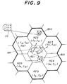
- FIG.9 shows radio zones employed by the present invention.
- steps which are the same as those corresponding steps in FIG.5 are designated by the same reference numerals, and a description thereof will be omitted.
- parts which are the same as those corresponding parts in FIG.1 are designated by the same reference numerals, and a description thereof will be omitted.
- frequency groups f1 through f7 are respectively assigned to the control channels C-CH of the radio zones RZ1 through RZ7, and the frequency groups f8 through f14 are respectively assigned to the voice channels V-CH of the radio zones RZ1 through RZ7.
- the mobile station MR constantly monitors the quality of the radio line in a step S1 shown in FIG.8 based on the field intensity or signal strength of the signal received from the base station BS1 and the code error rate of the demodulated signal.
- the mobile station MR moves from the radio zone RZ1 to the radio zone RZ2, for example, the mobile station MR detects that the signal strength or the code error rate has deteriorated and is now outside a tolerable range in a step S2.
- the mobile station MR uses a free time slot which is other than the time slot used by the mobile station MR for the communication with the base station BS1, and successively detects the signal strengths of the voice signals or the control signals from each of the neighboring base stations BS2 through BS7 in a step S3, where the control signals have frequencies corresponding to the radio zones RZ2 through RZ7 which are covered by the respective base stations BS2 through BS7.
- the mobile station MR determines the highest signal strength among the detected signal strengths in a step S4, so as to determine the base station which is to succeed the communication of the base station BS1.
- the base station BS2 succeeds the communication of the base station BS1 with the mobile station MR.
- the result of the determination made in the step S4 is sent from the mobile station MR to the base station BS1 to request a handover in a step S5.
- the base station BS1 which is communicating sends a handover request message to the control station CS in a step S6 in response to the handover request from the mobile station MR.
- the handover process becomes possible.
- the control station CS selects as the new voice channel the channel for communicating with the new base station BS2 of the radio zone RZ2 in which the mobile station MR is located.
- the control station CS notifies the handover message and the new voice channel to the mobile station MR, the base station BS1 which is communicating with the mobile station MR, and the new base station BS2 which is to succeed the communication of the base station BS1.
- the mobile station MR ends the communication with the base station BS1 and starts a communication with the new base station BS2 using the new voice channel.
- FIG.10 shows a receiving system of a mobile station which is used in this embodiment.
- those parts which are the same as those corresponding parts in FIG.4 are designated by the same reference numerals, and a description thereof will be omitted.
- a receiver 1 has the same construction as receiver 10 shown in FIG.4.
- An error rate detector 2 constantly detects the code error rate of the demodulated signal of the voice channel V-CH which is used for the communication between the mobile station MR and the base station BS, so as to detect the quality of the radio line.
- a circuit 3 compares the code error rate detected by the error rate detector 2 with a threshold value and compares the signal strength detected by the signal strength or field intensity detector 18 with a threshold value, and detects a deterioration of the communication quality when the code error rate and the signal strength are less than the respective threshold values for more than a predetermined time.
- the circuit 3 includes timers 31 and 32, and an OR circuit 33 which are connected as shown.
- a controller 4 controls the synthesizer 11 when the deterioration is detected by the circuit 3 or in response to an instruction from the control station CS.
- a maximum field intensity or signal strength detector 5 compares the signal strengths or field intensities of the control signals or the voice signals from each of the base stations BS measured by the detector 18 with a timing with which the controller 4 successively switches the tuning frequency of the synthesizer 11 for the control signal or the voice signal, and detects the base station BS from which the signal having the highest field intensity or signal strength is received.
- a transmitter 6 includes a modulator 61, a mixer 62, and a bandpass filter 63 which are connected as shown.
- the modulator 61 modulates an output signal of the maximum field intensity or signal strength detector 5.
- the mixer 62 mixes an output signal of the modulator 61 and the output signal of the synthesizer 11, and converts the signals into a signal having a desired transmission frequency.
- the bandpass filter 63 limits the band of the output signal of the mixer 62 into a predetermined band.
- the error rate detector 2 may detect the code error rate using the Viterbi code.
- the code error rate can be detected by counting the number of times the error correction is made.
- FIG.11 shows an embodiment of the error rate detector 2.
- the error rate detector 2 includes an error correction circuit 202, a timer 203 and a counter 204 which are connected as shown.
- the error correction circuit 202 receives the output of the demodulator 19 shown in FIG.10 via a terminal 201 and carries out an error correction.
- a demodulated signal is output from the error correction circuit 202 via a terminal 205.
- the timer 203 is set with a predetermined time, and the counter 204 counts the number of times the error correction is carried out in the error correction circuit 202 within the predetermined time set in the timer 203.
- An output signal of the counter 204 is supplied to the timer 31 shown in FIG.10 via a terminal 206.
- FIG.12 shows an embodiment of the maximum field intensity or signal strength detector 5.
- the detector 5 includes a comparator 502, a switch 503 and a zone determining circuit 504 which are connected as shown.
- the output signal of the field intensity or signal strength detector 18 shown in FIG.10 is applied to a terminal 501 and is output from a terminal 505 to be supplied to the timer 32 on one hand, and is supplied to terminals A of the comparator 502 and the switch 503 on the other.
- An output signal of the switch 503 is supplied to terminals B of the comparator 502 and the switch 503.
- the comparator 502 compares the magnitude of the field intensity or signal strength presently detected and received at the terminal A with the magnitude of the field intensity or signal strength previously detected and received at the terminal B, and outputs a signal which controls the switch 503 to connect to one of the terminals A and B which receives the field intensity or signal strength with the greater magnitude.
- the signal from the controller 4 shown in FIG.10 is supplied to the zone determining circuit 504 via a terminal 506, and the zone determining circuit 504 determines that the base station BS from which the field intensity last supplied to the terminal A originates is the base station BS of the radio zone RZ in which the mobile station MR is now located.
- An output signal of the zone determining circuit 504 indicative of this determination is supplied to the transmitter 6 shown in FIG.10 via a terminal 507.
- the mobile station MR is communicating with the base station BS1 using the time slot "a" of the voice channel V-CH.
- the controller 4 controls the synthesizer 11 based on the output of the OR circuit 33 so as to successively detect the field intensities or signal strengths of the signals from the neighboring base stations BS2 through BS7 (step S3).
- the synthesizer 11 uses the time slots "b" and "c” to successively scan the frequencies f2 through f7 of the control signals respectively assigned to the base stations BS2 through BS7.
- the mobile station MR which corresponds to the control/voice channel C/V-CH of the control signal shown in FIG.6 may continue to transmit a carrier or a dummy signal even when this mobile station MR is not communicating.
- the field intensities or signal strengths of the control signals assigned to each of the radio zones RZ2 through RZ7 are detected not in the control channel C-CH but in the control/voice channel C/V-CH during the unused time slots "b" and "c".
- the mobile station MR may detect the field intensities or signal strengths of the voice signals during the unused time slots "b" and "c" shown in FIG.7 by successively scanning the voice signals which are assigned to the radio zones RZ2 through RZ7 in the voice channel V-CH, instead of detecting the field intensities or signal strengths of the control signals shown in FIG.6.
- the frequency groups f9 through f14 of the voice channels V-CH of the voice signals which are assigned to each of the base stations BS2 through BS7 are successively scanned to determine which one of the signals from the base stations BS2 through BS7 has the highest field intensity or signal strength based on the field intensities or signal strengths of the frequency groups f9 through f14, because at least the dummy signal is transmitted from the base stations BS2 through BS7 during the time slots "b" and "c".
- the dummy signal in the voice channel V-CH is not transmitted if none of the voice channels V-CH are used.
- the detection of the signal in the voice channel V-CH is different from the detection of the control signal in the control channel C-CH in that the control signal is constantly transmitted in the control channel C-CH.
- the mobile station MR detects that the mobile station MR is located within the radio zone RZ of the base station BS from which the signal having the highest field intensity or signal strength is detected (step S4).
- the mobile station MR notifies the base station BS1 that the signal from the base station BS1 is becoming weak and the strongest signal is received from the base station BS2 using the control signal included in the voice channel V-CH (step S5).
- the mobile station MR may receive the correspondence of each frequency and the base stations BS2 through BS7 in advance from the base stations BS2 through BS7 using the control channel C-CH when the communication starts, or during the communication using the control signal included in the voice channel V-CH.
- the information related to the base station BS2 which corresponds to the radio zone RZ2 in which the frequency of the signal having the highest field intensity or signal strength is used may be notified from the mobile station MR to the base station BS1.
- the mobile station MR may notify to the base station BS1 the frequency of the signal which is detected as having the highest field intensity or signal strength, so that the base station BS1 may detect which base station BS corresponds to the detected frequency.
- the base station BS1 If the signal from the base station BS2 has the highest field intensity or signal strength, the base station BS1 notifies the control station CS of this information (step S6). Then, the control station CS selects as the new voice channel V-CH a free channel out of the voice channel group f9 which is assigned to the base station BS2 (step S17).
- control station CS notifies the handover message and the new voice channel V-CH to the base stations BS1 and BS2 (step S18), and the base station BS1 responsive thereto notifies the handover message and the new voice channel V-CH to the mobile station MR (step S19).
- the mobile station MR ends the communication with the base station BS1 and hands off the communication to the base station BS2 so as to start a communication with the base station BS2 using the new voice channel V-CH, and the handover control is completed.
Description
- The present invention generally relates to mobile radio communication systems, and more particularly to a mobile radio communication system which employs a multi-channel access system and is applicable to a mobile telephone or the like using radio zones.
- Recently, there are increasing numbers of users of the mobile radio communication system such as the mobile telephone. Hence, it is desirable that the mobile radio communication system employs a handover control procedure which enables fast and efficient communication, so that the service and the frequency utilization efficiency are improved.
- EP-A-0 318 033 discloses a mobile radio communication system employing time-divisional multiplex access (TDMA) and comprising a control station which is provided with respect to a control zone, the control zone being made up of a plurality of radio zones; a plurality of base stations, one for each of said radio zones; and a mobile station which is movable within the control zone. The mobile station comprises two separate receivers, a first receiver having a mixer and a demodulator for communication with the base stations, and a second receiver also having a mixer and a demodulator for receiving control signals from all base stations. The second receiver additionally has a level detector for determining the signal strength of the control signals constantly received from all base stations. Each control signal in each base station has a flag, either 0 or 1, indicating if this base stations has a free channel (flag: 1) or not (flag: 0). The second receiver provided with the level detector receives the control signals from the base stations and compares the reception levels only of those base stations having free channels (indicated by flag: 1), in order to monitor if the mobile station moves from one radio zone to another radio zone. When based on the comparison of reception levels a change of the radio zone is detected, and a switching request signal is transmitted from the mobile station through a current base station to the exchange or control station, then a switch to a destination base station having a free channel is performed. In summary, this mobile radio communication system uses signal strength monitoring performed by a second receiver in the mobile station, for determining when the mobile station leaves a particular radio zone covered by a particular base station assigned thereto, and which new radio zone is reached by the mobile station, for performing a handover to the new base station of the new radio zone. For this purpose each base station has to transmit a dedicated control signal containing a flag, which control signal is only used for monitoring a change of radio zones. Communication signals, on the other hand, are received by the mobile station through the first receiver thereof.
- US-A-4 829 519 discloses that monitoring of signal strength and the use of signal strength monitoring to determine when a transfer from one radio zone to another radio zone is to be made, is in itself inadequate.
- Therefore, this prior art document suggests that the mobile station should monitor a message transmitted from a base station, and based on this monitoring the mobile station determines a bit or symbol error rate above a threshold relating thereto, and the mobile station automatically sequentially monitors messages from adjacent base stations, such that the mobile station automatically switches from a first to a second base station the message of which has a bit or symbol error rate below threshold. In this respect two different kinds of messages transmitted from the base stations and monitored by the mobile station are suggested. The first kind of messages relates to "ordinary" messages which are error corrected in the mobile station for obtaining a correct message, then this corrected message is compared with the received message, and a signal quality assessment is performed based on the bit or symbol error rate. A second kind of messages relates to special quality assessment messages which according to the disclosure in this prior art document are preferable over ordinary messages. The quality assessment messages are transmitted by the base stations on every outbound channel, resulting in considerable expenditures with respect to the power required for transmissions in every outbound channel of the base stations, for example.
- For facilitating to understand the present invention, another mobile radio communication system using multi-channel access will be described hereinafter based on Figures 1 to 5.
- When a mobile station moves in the mobile radio communication system which uses the conventional multi-channel access (FDMA: frequency division multiplexing access) system and employs the radio zones, a handover is made when a called base station changes from an old base station to a new base station. In other words, the base station of an old radio zone in which the mobile station first exists and the base stations in neighboring radio zones measure the field intensity of a signal from the mobile station. A radio zone of the base station which receives the signal from the mobile station with the highest field intensity is regarded as a new radio zone in which the mobile station now exists.
- FIG.1 shows radio zones of an existing analog mobile telephone as an example of the conventional mobile radio communication system which uses the FDMA system and employs the radio zones. In FIG.1, a control zone CZ surrounded by a bold solid line includes a plurality of radio zones which are under control of a single control station CS. In this example, the control zone CZ includes seven radio zones RZ1 through RZ7. A base station BSi is provided in each radio zone RZi, where i = 1, 2, ..., 7. FIG.1 only shows a base station BS1 of the radio zone RZ1 and a base station BS2 of the radio zone RZ2. A mobile station MR exists within an arbitrary radio zone RZi within the control zone CZ. The mobile station MR may be a mobile telephone set equipped to an automobile or a portable telephone set which is hand carried by the user.
- In FIG.2, (A) and (B) respectively show control signals for controlling call-out and call-in, and in FIG.3, (A) and (B) respectively show voice signals. As shown in FIGS.2 and 3, a radio line uses a control channel C-CH and a voice channel V-CH which are not time-division-multiplexed. Hence, there is a going line from the base station BS1 or the like to the mobile station MR, and there is a returning line from the mobile station MR to the base station BS1 or the like.
- Moreover, one control channel group f1 is assigned to one control zone CZ, and voice channel groups f8 through f14 are respectively assigned to the radio zones RZ1 through RZ7 so that the frequencies of the voice channels do not overlap among the radio zones RZ1 through RZ7 within the same control zone CZ.
- FIG.4 shows an example of a receiving system of the base station in the conventional mobile radio communication system. The receiving system includes a
receiver 10 for receiving a voice channel signal, areceiver 20 exclusively for measuring the field intensity of a signal from the mobile station MR for the purpose of determining the radio zone in which the mobile station MR is located, and acontroller 30 for controllingsynthesizers respective receivers - In the
receiver 10, the received signal which passes through abandpass filter 12 is mixed to a first local signal which has a frequency set by thesynthesizer 11 in amixer 13 and is converted into a signal having a first intermediate frequency. The output signal of themixer 13 is passed through a bandpass filter 14a and is mixed to a second local signal which has a frequency set by asynthesizer 15 and is converted into a signal having a second intermediate frequency in amixer 16. The output signal of themixer 16 is passed through a bandpass filter 14b and is amplified by anintermediate frequency amplifier 17. Afield intensity detector 18 detects the field intensity of the received signal based on an output signal of theintermediate frequency amplifier 17 and notifies the detected field intensity to the control station CS. Ademodulator 19 demodulates the output signal of theintermediate frequency amplifier 17 and outputs an audio signal. - Similarly, in the
receiver 20, the received signal which passes through abandpass filter 22 is mixed to a first local signal which has a frequency set by thesynthesizer 21 in amixer 23 and is converted into a signal having a first intermediate frequency. The output signal of themixer 23 is passed through a bandpass filter 24a and is mixed to a second local signal which has a frequency set by asynthesizer 25 and is converted into a signal having a second intermediate frequency in amixer 26. The output signal of themixer 26 is passed through abandpass filter 24b and is amplified by anintermediate frequency amplifier 27. Afield intensity detector 28 detects the field intensity of the received signal based on an output signal of theintermediate frequency amplifier 27 and notifies the detected field intensity to the control station CS. - FIG.5 is a time chart for explaining a handover control procedure of the conventional mobile radio communication system which uses the base station shown in FIG.4. For the sake of convenience, it is assumed that the mobile station MR first exists within the radio zone RZ1 as shown in FIG.1 and communicates via the base station BS1 of the radio zone RZ1, and that the
synthesizer 11 within thereceiver 10 is tuned to the frequency of the mobile station MR in response to a frequency control signal from thecontroller 30 which receives an instruction from the control station CS. - In this case, when the base station BS1 is communicating, the
field intensity detector 18 within thereceiver 10 constantly monitors the field intensity of the signal from the mobile station MR in a step S11. - When the mobile station MR moves to the end of the radio zone RZ1 and moves from the radio zone RZ1 into the adjacent radio zone RZ2, the field intensity of the signal from the mobile station MR gradually decreases at the base station BS1. When the base station BS1 detects that the field intensity of the signal from the mobile station MR is less than a predetermined threshold value in a step S12, the base station BS1 notifies this information to the control station CS which controls the base station BS1 and the other neighboring base stations BS2 through BS7 within the control zone CZ in a step S13.
- Responsive to the information from the base station BS1, the control station CS instructs all of the base stations BS1 through BS7 within the control zone CZ including the base station BS1 to measure the field intensity of the signal received from the mobile station MR in a step S14. The
synthesizer 21 of thereceiver 20 within each of the base stations BS1 through BS7 is tuned to the frequency of the mobile station MR, so that the field intensity of the signal received from the mobile station MR is output from thefield intensity detector 28 within each of the base stations BS1 through BS7 within the control zone CZ in a step S15. - The base stations BS1 through BS7 respectively notify the measured field intensity of the signal received from the mobile station MR to the control station CS in a step S16.
- The control station CS compares the field intensities notified from the base stations BS1 through BS7 and selects one of the base stations BS1 through BS7 which outputs the highest field intensity, and at the same time, selects an available channel (or free frequency) out of the voice channel groups f9 through f14 which are assigned to the base stations BS1 through BS7, in a step S17.
- When it is assumed for the sake of convenience that the field intensity level notified from the base station BS2 is the highest, the control station CS notifies the base station BS1 of a handoff message and a new voice channel selected from the voice channel group f9 in a step S18 because the mobile station MR has now moved into the radio zone RZ2. This handoff message indicates that the communication between the communicating mobile station MR and the base station BS1 is ending. The base station BS1 transmits the received handoff message and the new voice channel to the mobile station MR and disconnects the transmission on the going line in a step S19.
- At the same time, the control station CS notifies the handoff message and the new voice channel to the base station BS2 because the mobile station MR has now moved into the radio zone RZ2. Hence, the base station BS2 is put ready to transmit using the new voice channel.
- The mobile station MR switches from the voice channel V-CH which is being used to the new voice channel in a step S20. In addition, the base station BS2 starts a communication with the mobile station MR using the new voice channel of the mobile station MR in a step S21.
- Hence, the voice channel between the base station BS2 and the mobile station MR is established in the above described manner.
- In the description given above, it is assumed for the sake of convenience that one mobile station MR moves within the control zone CZ. However, in actual practice, a plurality of mobile stations MR exist within the control zone CZ. Since the control zone CZ includes a plurality of radio zones RZ and each radio zone RZ has a radius in the order of several km, many mobile stations MR which require the handover may exist approximately at the same time.
- In such a case, because the control station CS of the conventional system monitors the radio zones RZ1 through RZ7 within the control zone CZ, the control station CS cannot process the handovers which are simultaneously generated in a plurality of radio zones RZ within the control zone CZ. In addition, since each base station BS is only provided with a limited number of
receivers - Moreover, there is a problem in that the base station BS must be provided with the
receiver 20 for measuring the field intensity of the signal from the mobile station MR in addition to thenormal receiver 10 which is used for the communication. - Accordingly, it is a general object of the present invention to provide a novel and useful mobile radio communication system which has a simpler construction than the system according to EP-A-0 318 033.
- This is achieved according to the present invention by a mobile radio communication system according to claim 1.
- Preferred embodiments of the invention are indicated in the dependent claims.
- According to the mobile radio communication system of the present invention, it is possible to prevent the mobile station from waiting for the handover even when a plurality of mobile stations within the same control zone simultaneously request handovers. In addition, it is unnecessary to provide in the base station or the mobile station a receiver exclusively for detecting the field intensity or signal strength for detecting the radio zone of the mobile station. Therefore, it is possible to carry out the handover process at a high speed with a high efficiency so as to enable the communication between the mobile station and the second base station using the new communication channel.
- Other objects and further features of the present invention will be apparent from the following detailed description when read in conjunction with the accompanying drawings.
-
- FIG.1 is a diagram for explaining radio zones;
- FIGS.2 and 3 are diagrams for explaining a control signal and a voice signal which are used in the multi-channel access system;
- FIG.4 is a system block diagram showing an example of a receiving system of a base station which is used in a conventional mobile radio communication system;
- FIG.5 is a time chart for explaining an operation of the conventional mobile radio communication system;
- FIGS.6 and 7 are diagrams for explaining a control signal and a voice signal which are used in the present invention;
- FIG.8 is a time chart for explaining an operating principle of a mobile radio communication system according to the present invention;
- FIG.9 is a diagram for explaining radio zones employed in the present invention;
- FIG.10 is a system block diagram showing a receiving system of a mobile station used in an embodiment of the mobile radio communication system according to the present invention;
- FIG.11 is a system block diagram showing an embodiment of an error rate detector shown in FIG.10; and
- FIG.12 is a system block diagram showing an embodiment of a maximum field intensity detector shown in FIG.10.
- As shown in FIGS.2 and 3, both the control signal and the voice signal continuously exist for predetermined time periods according to the conventional mobile radio communication system which uses the multi-channel access system. For this reason, the channels are occupied during the predetermined time periods and cannot be used for other purposes.
- Accordingly, the present invention employs the time division multiplexing access (TDMA) system which time divides both the control signal and the voice signal in time slots as shown in FIGS.6 and 7. In FIG.6, (A) and (B) respectively show the control signal transmitted from the base station BS to the mobile station MR and the control signal transmitted from the mobile station MR to the base station BS. In FIG.7, (A) and (B) respectively show the voice signal transmitted from the base station BS to the mobile station MR and the voice signal transmitted from the mobile station MR to the base station BS.
- As shown, both the control signal and the voice signal are constantly transmitted on the going line. But the receiver of a mobile station MR does not receive any information during time slots other than a time slot which is assigned to this mobile station MR. For example, when the time slot "a" is assigned to the mobile station MR, the receiver of this mobile station MR does not receive any information during the time slots "b" and "c".
- As shown in FIG.6, a control channel C-CH is assigned to each radio zone RZ, and the receiving system of the mobile station MR can measure the field intensity or signal strength of the signals from each of the base stations BS at an arbitrary time by scanning the frequencies of the control signals of the neighboring base stations BS during a time slot other than the time slot used by the mobile station MR. The frequencies of the control signals which are scanned correspond to the frequency groups fl through f7 of the control signals assigned to each of the radio zones RZ, for example, as will be described later. In addition, the time slot other than the time slot used by the mobile station MR is a free time slot. In FIG.6, the time slot "a" is used as the control channel C-CH, while the time slots "b" and "c" are used either as the control channel C-CH or the voice channel V-CH (control/voice channel C/V-CH).
- Therefore, even when a plurality of mobile stations MR exist within the radio zone RZ, each mobile station MR can measure the field intensity or signal strength of the signals from each of the base stations BS at an arbitrary time by scanning the frequency groups f8 through f14 of the voice signals during a free time slot other than the time slot ("a" in the above example) used by the mobile station MR, even when the signals are carriers transmitted from the base stations BS.
- A description will now be given of the operating principle of the mobile radio communication system according to the present invention which employs the handover control procedure, by referring to FIGS.8 and 9. FIG.8 is a time chart for explaining the operation of the mobile radio communication system according to the present invention, and FIG.9 shows radio zones employed by the present invention. In FIG.8, those steps which are the same as those corresponding steps in FIG.5 are designated by the same reference numerals, and a description thereof will be omitted. Furthermore, in FIG.9, those parts which are the same as those corresponding parts in FIG.1 are designated by the same reference numerals, and a description thereof will be omitted. In FIG.9, frequency groups f1 through f7 are respectively assigned to the control channels C-CH of the radio zones RZ1 through RZ7, and the frequency groups f8 through f14 are respectively assigned to the voice channels V-CH of the radio zones RZ1 through RZ7.
- The mobile station MR constantly monitors the quality of the radio line in a step S1 shown in FIG.8 based on the field intensity or signal strength of the signal received from the base station BS1 and the code error rate of the demodulated signal. When the mobile station MR moves from the radio zone RZ1 to the radio zone RZ2, for example, the mobile station MR detects that the signal strength or the code error rate has deteriorated and is now outside a tolerable range in a step S2. The mobile station MR uses a free time slot which is other than the time slot used by the mobile station MR for the communication with the base station BS1, and successively detects the signal strengths of the voice signals or the control signals from each of the neighboring base stations BS2 through BS7 in a step S3, where the control signals have frequencies corresponding to the radio zones RZ2 through RZ7 which are covered by the respective base stations BS2 through BS7. In addition, the mobile station MR determines the highest signal strength among the detected signal strengths in a step S4, so as to determine the base station which is to succeed the communication of the base station BS1. In this case, the base station BS2 succeeds the communication of the base station BS1 with the mobile station MR.
- The result of the determination made in the step S4 is sent from the mobile station MR to the base station BS1 to request a handover in a step S5. Hence, the base station BS1 which is communicating sends a handover request message to the control station CS in a step S6 in response to the handover request from the mobile station MR. As a result, the handover process becomes possible.
- Thereafter, the control station CS selects as the new voice channel the channel for communicating with the new base station BS2 of the radio zone RZ2 in which the mobile station MR is located. In addition, the control station CS notifies the handover message and the new voice channel to the mobile station MR, the base station BS1 which is communicating with the mobile station MR, and the new base station BS2 which is to succeed the communication of the base station BS1. Thereafter, the mobile station MR ends the communication with the base station BS1 and starts a communication with the new base station BS2 using the new voice channel.
- Next, a description will be given of an embodiment of the mobile radio communication system according to the present invention, by referring to FIG.10. FIG.10 shows a receiving system of a mobile station which is used in this embodiment. In FIG.10, those parts which are the same as those corresponding parts in FIG.4 are designated by the same reference numerals, and a description thereof will be omitted.
- In FIG.10, a receiver 1 has the same construction as
receiver 10 shown in FIG.4. Anerror rate detector 2 constantly detects the code error rate of the demodulated signal of the voice channel V-CH which is used for the communication between the mobile station MR and the base station BS, so as to detect the quality of the radio line. Acircuit 3 compares the code error rate detected by theerror rate detector 2 with a threshold value and compares the signal strength detected by the signal strength orfield intensity detector 18 with a threshold value, and detects a deterioration of the communication quality when the code error rate and the signal strength are less than the respective threshold values for more than a predetermined time. Thecircuit 3 includestimers OR circuit 33 which are connected as shown. - A controller 4 controls the
synthesizer 11 when the deterioration is detected by thecircuit 3 or in response to an instruction from the control station CS. A maximum field intensity orsignal strength detector 5 compares the signal strengths or field intensities of the control signals or the voice signals from each of the base stations BS measured by thedetector 18 with a timing with which the controller 4 successively switches the tuning frequency of thesynthesizer 11 for the control signal or the voice signal, and detects the base station BS from which the signal having the highest field intensity or signal strength is received. - A
transmitter 6 includes amodulator 61, amixer 62, and abandpass filter 63 which are connected as shown. Themodulator 61 modulates an output signal of the maximum field intensity orsignal strength detector 5. Themixer 62 mixes an output signal of themodulator 61 and the output signal of thesynthesizer 11, and converts the signals into a signal having a desired transmission frequency. Thebandpass filter 63 limits the band of the output signal of themixer 62 into a predetermined band. - For example, the
error rate detector 2 may detect the code error rate using the Viterbi code. In this case, the code error rate can be detected by counting the number of times the error correction is made. - FIG.11 shows an embodiment of the
error rate detector 2. Theerror rate detector 2 includes anerror correction circuit 202, atimer 203 and acounter 204 which are connected as shown. Theerror correction circuit 202 receives the output of thedemodulator 19 shown in FIG.10 via aterminal 201 and carries out an error correction. A demodulated signal is output from theerror correction circuit 202 via aterminal 205. Thetimer 203 is set with a predetermined time, and thecounter 204 counts the number of times the error correction is carried out in theerror correction circuit 202 within the predetermined time set in thetimer 203. An output signal of thecounter 204 is supplied to thetimer 31 shown in FIG.10 via aterminal 206. - FIG.12 shows an embodiment of the maximum field intensity or
signal strength detector 5. Thedetector 5 includes acomparator 502, aswitch 503 and azone determining circuit 504 which are connected as shown. The output signal of the field intensity orsignal strength detector 18 shown in FIG.10 is applied to a terminal 501 and is output from a terminal 505 to be supplied to thetimer 32 on one hand, and is supplied to terminals A of thecomparator 502 and theswitch 503 on the other. An output signal of theswitch 503 is supplied to terminals B of thecomparator 502 and theswitch 503. Thecomparator 502 compares the magnitude of the field intensity or signal strength presently detected and received at the terminal A with the magnitude of the field intensity or signal strength previously detected and received at the terminal B, and outputs a signal which controls theswitch 503 to connect to one of the terminals A and B which receives the field intensity or signal strength with the greater magnitude. The signal from the controller 4 shown in FIG.10 is supplied to thezone determining circuit 504 via a terminal 506, and thezone determining circuit 504 determines that the base station BS from which the field intensity last supplied to the terminal A originates is the base station BS of the radio zone RZ in which the mobile station MR is now located. An output signal of thezone determining circuit 504 indicative of this determination is supplied to thetransmitter 6 shown in FIG.10 via aterminal 507. - Next, a description will be given of the operation of this embodiment, by referring to FIGS.6 through 9.
- It is assumed for the sake of convenience that the mobile station MR is communicating with the base station BS1 using the time slot "a" of the voice channel V-CH. In this case, when the field intensity or signal strength and the code error rate respectively detected by the field intensity or
signal strength detector 18 and the error rate detector 2 (step S1) deteriorate to values less than the respective threshold values continuously for the predetermined times set in therespective timers 32 and 31 (step S2), the controller 4 controls thesynthesizer 11 based on the output of theOR circuit 33 so as to successively detect the field intensities or signal strengths of the signals from the neighboring base stations BS2 through BS7 (step S3). In other words, thesynthesizer 11 uses the time slots "b" and "c" to successively scan the frequencies f2 through f7 of the control signals respectively assigned to the base stations BS2 through BS7. - Depending on the system used, the mobile station MR which corresponds to the control/voice channel C/V-CH of the control signal shown in FIG.6 may continue to transmit a carrier or a dummy signal even when this mobile station MR is not communicating. In such a case, the field intensities or signal strengths of the control signals assigned to each of the radio zones RZ2 through RZ7 are detected not in the control channel C-CH but in the control/voice channel C/V-CH during the unused time slots "b" and "c".
- On the other hand, the mobile station MR may detect the field intensities or signal strengths of the voice signals during the unused time slots "b" and "c" shown in FIG.7 by successively scanning the voice signals which are assigned to the radio zones RZ2 through RZ7 in the voice channel V-CH, instead of detecting the field intensities or signal strengths of the control signals shown in FIG.6.
- In other words, during the time slots "b" and "c" which are unused by the mobile station MR, the frequency groups f9 through f14 of the voice channels V-CH of the voice signals which are assigned to each of the base stations BS2 through BS7 are successively scanned to determine which one of the signals from the base stations BS2 through BS7 has the highest field intensity or signal strength based on the field intensities or signal strengths of the frequency groups f9 through f14, because at least the dummy signal is transmitted from the base stations BS2 through BS7 during the time slots "b" and "c".
- However, the dummy signal in the voice channel V-CH is not transmitted if none of the voice channels V-CH are used. Hence, the detection of the signal in the voice channel V-CH is different from the detection of the control signal in the control channel C-CH in that the control signal is constantly transmitted in the control channel C-CH.
- As a result of the detection described above, the mobile station MR detects that the mobile station MR is located within the radio zone RZ of the base station BS from which the signal having the highest field intensity or signal strength is detected (step S4). When it is assumed for the sake of convenience that the signal having the highest field intensity or signal strength is received from the base station BS2, it is detected that the mobile station MR is located within the radio zone RZ2. In this case, the mobile station MR notifies the base station BS1 that the signal from the base station BS1 is becoming weak and the strongest signal is received from the base station BS2 using the control signal included in the voice channel V-CH (step S5).
- The mobile station MR may receive the correspondence of each frequency and the base stations BS2 through BS7 in advance from the base stations BS2 through BS7 using the control channel C-CH when the communication starts, or during the communication using the control signal included in the voice channel V-CH. In this case, the information related to the base station BS2 which corresponds to the radio zone RZ2 in which the frequency of the signal having the highest field intensity or signal strength is used may be notified from the mobile station MR to the base station BS1. On the other hand, when the correspondence of the frequencies and the base stations BS2 through BS7 is unknown at the mobile station MR, the mobile station MR may notify to the base station BS1 the frequency of the signal which is detected as having the highest field intensity or signal strength, so that the base station BS1 may detect which base station BS corresponds to the detected frequency.
- If the signal from the base station BS2 has the highest field intensity or signal strength, the base station BS1 notifies the control station CS of this information (step S6). Then, the control station CS selects as the new voice channel V-CH a free channel out of the voice channel group f9 which is assigned to the base station BS2 (step S17).
- In addition, the control station CS notifies the handover message and the new voice channel V-CH to the base stations BS1 and BS2 (step S18), and the base station BS1 responsive thereto notifies the handover message and the new voice channel V-CH to the mobile station MR (step S19).
- Accordingly, the mobile station MR ends the communication with the base station BS1 and hands off the communication to the base station BS2 so as to start a communication with the base station BS2 using the new voice channel V-CH, and the handover control is completed.
- Further, the present invention is not limited to these embodiments, but various variations and modifications may be made without departing from the scope of the present invention.
- Reference signs in the claims are intended for better understanding and shall not limit the scope.
Claims (13)
- A mobile radio communication system employing time-divisional multiplex access (TDMA) and comprising a control station (CS) which is provided with respect to a control zone (CZ), said control zone being made up of a plurality of radio zones (RZ1-RZ7); a plurality of base stations (BS1-BS7), one for each of said radio zones; and a mobile station (MR) which is movable within the control zone;wherein the communication between a particular base station (e.g. BS1) and said mobile station (MR) is performed in a particular time slot (a) assigned to said mobile station (MR) among the time slots (a,b,c, ...) available for communication based on time-divisional multiplex access;said mobile station (MR) comprisinga single receiving means (1) for communicating with any one of said base stations (BS1-BS7);first means (2) coupled to said receiving means (1) for monitoring a quality of a radio line between said mobile station (MR) and a first base station (BS1) with which said mobile station is presently communicating, said first base station (BS1) being provided with respect to a first radio zone (RZ1);second means (3) coupled to said first means (2) for detecting a deterioration of the quality of the radio line between said mobile station (MR) and said first base station (BS1) outside a tolerable range;third means (5) coupled to said receiving means (2) for detecting signal strengths of signals received from the base stations (BS2-BS7) neighbouring said first base station (BS1) using a time slot (b,c, ...) different from that particular time slot (a) which is used by said mobile station (MR) for communication with said first base station (BS1) and for determining a maximum signal strength of the received signals;fourth means (6) coupled to said third means (5) for supplying to said first base station (BS1) predetermined information related to a second base station (BS2) from which the signal with the maximum signal strength is received so as to make a handover request;and fifth means (4) for ending a communication with said first base station (BS1) in response to a handover message, said second base station (BS2) being provided with respect to a second radio zone (RZ2) which is different from said first radio zone (RZ1);wherein said first base station (BS1) includes means for supplying a handover request message to said control station (CS) in response to the handover request from said mobile station (MR);and said control station (CS) includes means for carrying out a handover process in response to the handover request message,said handover process including selecting a new communication channel with which said mobile station (MR) is to communicate with said second base station (BS2) when said mobile station (MR) moves from said first radio zone (RZ1) to said second radio zone (RZ2), and notifying the handover message and the new communication channel to said mobile station (MR) and said first and second base stations (BS1,BS2), so that said mobile station (MR) ends the communication with said first base station (BS1) in response to the handover message and starts a communication with said second base station (BS2) using the new communication channel.
- The mobile radio communication system as claimed in claim 1, characterized in that mutually different first frequency groups (f1-f7) are assigned to said radio zones (RZ1-RZ7) for a control signal which is used for controlling call-out and call-in on a radio line, and mutually different second frequency groups (f8-f14) are assigned to said radio zones for a communication signal which is used for the communication, said first and second frequency groups including no overlapping frequencies within said control zone (CZ), said control signal and said communication signal respectively being transmitted time-divisionally in time slots in conformance with said time division multiplex access system.
- The mobile radio communication system as claimed in claim 2, characterized in that said predetermined information includes a frequency of the signal which is detected by said third means (5) as having the maximum signal strength.
- The mobile radio communication system as claimed in claim 2 or 3, characterized in that said third means (5) detects the signal strengths of the signals received from the neighboring base stations (BS2-BS7) by successively scanning control channels (C-CH) which correspond to the first frequency groups (f1-f7).
- The mobile radio communication system as claimed in claim 4, characterized in that said neighboring base stations (BS2-BS7) constantly transmit carriers in the control channels (C-CH), so that said third means (5) can successively detect the signal strength of the signals the control channels (C-CH) during time slots (b,c,...) other than the time slot (a) used by said mobile station (MR).
- The mobile radio communication system as claimed in claim 2 or 3, characterized in that said third means (5) detects the signal strengths of the signals received from the neighboring base stations (BS2-BS7) by successively scanning communication channels (V-CH) which correspond to the second frequency groups (f8-f14).
- The mobile radio communication system as claimed in claim 6, characterized in that said neighboring base stations (BS2-BS7) constantly transmit carriers in the communication channels (V-CH), so that said third means (5) can successively detect the signal strengths of the signals in the communication channels during time slots (b,c,...) other than the time slot (a) used by said mobile station (MR).
- The mobile radio communication system as claimed in any of claims 1 to 7, characterized in that said mobile station (MR) receives prior to a start of a communication specific information related to correspondence of frequencies (f1-f14) and the base stations (BS1-BS7) which are provided with respect to the radio zones (RZ1-RZ7) assigned with the frequencies.
- The mobile radio communication system as claimed in claim 8, characterized in that said mobile station (MR) receives the specific information using a control channel (C-CH) which corresponds to one of the first frequency groups (f1-f7).
- The mobile radio communication system as claimed in any of claims 1 to 7, characterized in that said mobile station (MR) receives during a communication specific information related to correspondence of frequencies (f1-f14) and the base stations (BS1-BS7) which are provided with respect to the radio zones (RZ1-RZ7) assigned with the frequencies.
- The mobile radio communication system as claimed in claim 10, characterized in that said mobile station (MR) receives the specific information using a communication channel (V-CH) which corresponds to one of the second frequency groups (f8-f14).
- The mobile radio communication system as claimed in any of claims 1 to 11, characterized in that said second means (3) includes monitoring means (18, 2) for monitoring the signal strength of a signal received from said first base station (BS1) and a code error rate of a demodulated signal which is obtained by demodulation of the signal received from said first base station, and detecting means (3) for detecting the deterioration of the quality of the radio line when at least one of the monitored signal strength and code error rate becomes less than a corresponding threshold value continuously for a predetermined time.
- The mobile radio communication system as claimed in claim 12, characterized in that said monitoring means (18, 2) monitors the code error rate by detecting a number of times an error correction is made with respect to the demodulated signal within a given time.
Priority Applications (1)
| Application Number | Priority Date | Filing Date | Title |
|---|---|---|---|
| EP96106014A EP0727915B1 (en) | 1990-03-19 | 1991-03-18 | Mobile radio communication system |
Applications Claiming Priority (2)
| Application Number | Priority Date | Filing Date | Title |
|---|---|---|---|
| JP68918/90 | 1990-03-19 | ||
| JP2068918A JPH03268697A (en) | 1990-03-19 | 1990-03-19 | Mobile radio communication system |
Related Child Applications (2)
| Application Number | Title | Priority Date | Filing Date |
|---|---|---|---|
| EP96106014A Division EP0727915B1 (en) | 1990-03-19 | 1991-03-18 | Mobile radio communication system |
| EP96106014.2 Division-Into | 1991-03-18 |
Publications (3)
| Publication Number | Publication Date |
|---|---|
| EP0448015A2 EP0448015A2 (en) | 1991-09-25 |
| EP0448015A3 EP0448015A3 (en) | 1992-07-15 |
| EP0448015B1 true EP0448015B1 (en) | 1996-10-30 |
Family
ID=13387514
Family Applications (2)
| Application Number | Title | Priority Date | Filing Date |
|---|---|---|---|
| EP96106014A Expired - Lifetime EP0727915B1 (en) | 1990-03-19 | 1991-03-18 | Mobile radio communication system |
| EP91104154A Expired - Lifetime EP0448015B1 (en) | 1990-03-19 | 1991-03-18 | Mobile radio communication system |
Family Applications Before (1)
| Application Number | Title | Priority Date | Filing Date |
|---|---|---|---|
| EP96106014A Expired - Lifetime EP0727915B1 (en) | 1990-03-19 | 1991-03-18 | Mobile radio communication system |
Country Status (5)
| Country | Link |
|---|---|
| US (1) | US5117502A (en) |
| EP (2) | EP0727915B1 (en) |
| JP (1) | JPH03268697A (en) |
| CA (1) | CA2038473C (en) |
| DE (2) | DE69122900T2 (en) |
Cited By (1)
| Publication number | Priority date | Publication date | Assignee | Title |
|---|---|---|---|---|
| RU2572829C1 (en) * | 2014-09-03 | 2016-01-20 | Открытое акционерное общество "Научно-производственное предприятие "Полет" | System for locating mobile objects |
Families Citing this family (78)
| Publication number | Priority date | Publication date | Assignee | Title |
|---|---|---|---|---|
| US5230082A (en) * | 1990-08-16 | 1993-07-20 | Telefonaktiebolaget L M Ericsson | Method and apparatus for enhancing signalling reliability in a cellular mobile radio telephone system |
| JPH04274627A (en) * | 1991-03-01 | 1992-09-30 | Toshiba Corp | Mobile station equipment |
| US5175867A (en) * | 1991-03-15 | 1992-12-29 | Telefonaktiebolaget L M Ericsson | Neighbor-assisted handoff in a cellular communications system |
| DE69228676T2 (en) * | 1991-09-24 | 1999-10-07 | Motorola Inc | CELLULAR RADIO SYSTEM WITH COMMON RADIO MAIN NETWORK |
| JP3043171B2 (en) * | 1992-02-25 | 2000-05-22 | 富士通株式会社 | Control channel monitor method |
| CA2062040C (en) * | 1992-02-28 | 2001-01-16 | Deborah Pinard | Mobile wireless communications system |
| US5579379A (en) * | 1992-03-05 | 1996-11-26 | Bell Atlantic Network Services, Inc. | Personal communications service having a calling party pays capability |
| US5353331A (en) * | 1992-03-05 | 1994-10-04 | Bell Atlantic Network Services, Inc. | Personal communications service using wireline/wireless integration |
| US5295153A (en) * | 1992-04-13 | 1994-03-15 | Telefonaktiebolaget L M Ericsson | CDMA frequency allocation |
| FI96157C (en) * | 1992-04-27 | 1996-05-10 | Nokia Mobile Phones Ltd | Digital cellular radio telephone network based on time multiplexing to move a radio connection from the base station to a new base station |
| FI95187C (en) * | 1992-11-30 | 1995-12-27 | Nokia Telecommunications Oy | A method for measuring adjacent base stations in a TDMA radio system and a TDMA radio system |
| FR2699357B1 (en) * | 1992-12-16 | 1995-01-13 | Alcatel Radiotelephone | Device for searching for the connection of a terminal to a network of a radiocommunication system comprising several networks. |
| US5440613A (en) * | 1992-12-30 | 1995-08-08 | At&T Corp. | Architecture for a cellular wireless telecommunication system |
| US5325419A (en) * | 1993-01-04 | 1994-06-28 | Ameritech Corporation | Wireless digital personal communications system having voice/data/image two-way calling and intercell hand-off |
| FR2702111B1 (en) * | 1993-02-26 | 1995-05-12 | Alcatel Radiotelephone | Method for managing transmission errors between a base station and a transcoder in a digital radiocommunication system, corresponding base station and transcoder. |
| US5715235A (en) * | 1993-11-26 | 1998-02-03 | Ntt Mobile Communications Network Inc. | Communication system capable of performing FDMA transmission |
| JP2902964B2 (en) * | 1994-11-25 | 1999-06-07 | 三洋電機株式会社 | Digital mobile phone |
| US5764648A (en) * | 1994-07-20 | 1998-06-09 | Sanyo Electric Co., Ltd. | Method and apparatus for generating a transmission timing signal in a wireless telephone |
| EP1657947B1 (en) * | 1994-10-04 | 2009-03-25 | Ntt Mobile Communications Network Inc. | Mobile communication system and handover method |
| WO1996013132A1 (en) * | 1994-10-24 | 1996-05-02 | Ameritech Corporation | Wireless digital personal communications system having voice/data/image two-way calling and intercell hand-off |
| US6035197A (en) | 1994-12-29 | 2000-03-07 | Cellco Partnership | Method and system for providing a handoff from a CDMA cellular telephone system |
| DE4447243B4 (en) * | 1994-12-30 | 2004-02-19 | Siemens Ag | Method of controlling connections in communication systems with wireless signal transmission |
| JP2693922B2 (en) * | 1995-02-13 | 1997-12-24 | 日本電気エンジニアリング株式会社 | Channel switching determination device for mobile wireless terminal |
| US5805999A (en) * | 1995-02-15 | 1998-09-08 | Nec Corporation | Cordless phone system and a method for estimating location of a cordless phone in said cordless phone system |
| US5778026A (en) * | 1995-04-21 | 1998-07-07 | Ericsson Inc. | Reducing electrical power consumption in a radio transceiver by de-energizing selected components when speech is not present |
| CN1085019C (en) | 1995-05-31 | 2002-05-15 | 西门子公司 | Mobile radiotelephone reception equipment for cellular radio telephone system |
| GB2303998B (en) * | 1995-08-03 | 2000-03-01 | Nokia Mobile Phones Ltd | Radio telephones and methods of operation |
| US5621787A (en) * | 1995-09-13 | 1997-04-15 | Bell Atlantic Network Services, Inc. | Prepaid cash card |
| US5661724A (en) | 1995-12-18 | 1997-08-26 | Ericsson Inc. | Satellite diversity scheme |
| EP0786917B1 (en) * | 1996-01-23 | 2013-08-21 | Ntt Mobile Communications Network Inc. | Mobile communication system, network and mobile station |
| US5774809A (en) * | 1996-02-12 | 1998-06-30 | Nokia Mobile Phones Limited | Simplified mobile assisted handoff of signal between cells |
| SE506816C2 (en) * | 1996-06-20 | 1998-02-16 | Ericsson Telefon Ab L M | A method and a communication unit for the rapid identification of base stations in a communication network |
| JP3224345B2 (en) * | 1996-06-24 | 2001-10-29 | 株式会社エヌ・ティ・ティ・ドコモ | Handover type determination method in CDMA mobile communication system and CDMA mobile communication system |
| GB2314734B (en) * | 1996-06-28 | 2000-11-01 | Motorola Ltd | Method and apparatus for monitoring channels |
| KR100292318B1 (en) * | 1996-09-25 | 2001-08-07 | 모리시타 요이찌 | Base station equipment for mobile communication |
| US6819927B1 (en) | 1996-10-18 | 2004-11-16 | Matsushita Electric Industrial Co., Ltd. | Communication method for use by a mobile station in a mobile communication system of CDMA |
| JP3369063B2 (en) | 1996-10-18 | 2003-01-20 | 松下電器産業株式会社 | Mobile communication terminal |
| JP2002501684A (en) | 1996-12-04 | 2002-01-15 | ノキア テレコミュニケーションズ オサケユイチア | Handover control in mobile communication networks |
| JPH10200937A (en) | 1997-01-16 | 1998-07-31 | Nec Corp | Method for monitoring adjacent cell and mobile communication system of time division digital system |
| JPH10215484A (en) * | 1997-01-29 | 1998-08-11 | Nippon Denki Ido Tsushin Kk | Digital cordless telephone system |
| WO1998044750A2 (en) * | 1997-03-27 | 1998-10-08 | Siemens Aktiengesellschaft | Method and device for data transmission |
| DE19715934C1 (en) * | 1997-04-16 | 1999-06-17 | Siemens Ag | Method and arrangement for determining the transmission quality of a radio channel |
| JP2990098B2 (en) * | 1997-05-21 | 1999-12-13 | 埼玉日本電気株式会社 | Terminal-driven mobile communication system |
| US5974320A (en) * | 1997-05-21 | 1999-10-26 | Telefonaktiebolaget Lm Ericsson (Publ) | Providing a neighborhood zone within a mobile telecommunications network |
| US6141555A (en) * | 1997-06-09 | 2000-10-31 | Nec Corporation | Cellular communication system, and mobile and base stations used in the same |
| FI972561A (en) * | 1997-06-16 | 1998-12-17 | Nokia Telecommunications Oy | Communication method and radio system |
| US6009124A (en) * | 1997-09-22 | 1999-12-28 | Intel Corporation | High data rate communications network employing an adaptive sectored antenna |
| GB2330484A (en) * | 1997-10-15 | 1999-04-21 | Motorola As | Mobile initiated handover during periods of communication inactivity |
| DE19804185A1 (en) * | 1998-02-03 | 1999-08-05 | Siemens Ag | Method and device for exchanging signaling information between base stations in a mobile radio system |
| US6728540B1 (en) * | 1998-03-09 | 2004-04-27 | Avaya Technology Corp. | Assisted handover in a wireless communication system |
| US6181943B1 (en) * | 1998-03-30 | 2001-01-30 | Lucent Technologies Inc. | Method and apparatus for inter-frequency hand-off in wireless communication systems |
| AU7935898A (en) * | 1998-06-30 | 2000-01-17 | Mitsubishi Denki Kabushiki Kaisha | Mobile communication terminal |
| US6360100B1 (en) * | 1998-09-22 | 2002-03-19 | Qualcomm Incorporated | Method for robust handoff in wireless communication system |
| KR100311506B1 (en) * | 1998-11-04 | 2001-11-15 | 서평원 | HandOff Control Method in Mobile Communication System |
| US6434386B1 (en) | 1998-12-31 | 2002-08-13 | Telefonaktiebolaget L M Ericsson (Publ) | Method and system for monitoring power output in transceivers |
| JP3241018B2 (en) * | 1999-01-22 | 2001-12-25 | 三菱マテリアル株式会社 | Mobile radio, base station radio, and recording medium thereof |
| JP3344472B2 (en) * | 1999-05-20 | 2002-11-11 | 日本電気株式会社 | Mobile communication method |
| US7188341B1 (en) * | 1999-09-24 | 2007-03-06 | New York Air Brake Corporation | Method of transferring files and analysis of train operational data |
| US7039436B1 (en) * | 2000-01-12 | 2006-05-02 | Mitsubishi Denki Kabushiki Kaisha | Mobile communication terminal |
| KR100474689B1 (en) * | 2001-08-30 | 2005-03-08 | 삼성전자주식회사 | Method for power control during soft handoff in mobile communication system |
| US6795419B2 (en) * | 2002-03-13 | 2004-09-21 | Nokia Corporation | Wireless telecommunications system using multislot channel allocation for multimedia broadcast/multicast service |
| JP3999573B2 (en) * | 2002-06-05 | 2007-10-31 | 株式会社エヌ・ティ・ティ・ドコモ | COMMUNICATION SYSTEM, COMMUNICATION METHOD, AND CONTROL DEVICE |
| US7668541B2 (en) * | 2003-01-31 | 2010-02-23 | Qualcomm Incorporated | Enhanced techniques for using core based nodes for state transfer |
| JP5049463B2 (en) | 2004-12-14 | 2012-10-17 | 富士通株式会社 | Wireless communication system, base station, mobile station, and wireless communication method |
| US9078084B2 (en) | 2005-12-22 | 2015-07-07 | Qualcomm Incorporated | Method and apparatus for end node assisted neighbor discovery |
| US8983468B2 (en) * | 2005-12-22 | 2015-03-17 | Qualcomm Incorporated | Communications methods and apparatus using physical attachment point identifiers |
| US9736752B2 (en) | 2005-12-22 | 2017-08-15 | Qualcomm Incorporated | Communications methods and apparatus using physical attachment point identifiers which support dual communications links |
| US8509799B2 (en) | 2005-09-19 | 2013-08-13 | Qualcomm Incorporated | Provision of QoS treatment based upon multiple requests |
| US8982778B2 (en) | 2005-09-19 | 2015-03-17 | Qualcomm Incorporated | Packet routing in a wireless communications environment |
| US9066344B2 (en) | 2005-09-19 | 2015-06-23 | Qualcomm Incorporated | State synchronization of access routers |
| US8982835B2 (en) * | 2005-09-19 | 2015-03-17 | Qualcomm Incorporated | Provision of a move indication to a resource requester |
| US9083355B2 (en) | 2006-02-24 | 2015-07-14 | Qualcomm Incorporated | Method and apparatus for end node assisted neighbor discovery |
| CN101119579B (en) * | 2006-07-31 | 2010-09-22 | 华为技术有限公司 | Hard handoff measurement control method and system |
| US9155008B2 (en) | 2007-03-26 | 2015-10-06 | Qualcomm Incorporated | Apparatus and method of performing a handoff in a communication network |
| US8830818B2 (en) | 2007-06-07 | 2014-09-09 | Qualcomm Incorporated | Forward handover under radio link failure |
| US9094173B2 (en) | 2007-06-25 | 2015-07-28 | Qualcomm Incorporated | Recovery from handoff error due to false detection of handoff completion signal at access terminal |
| US8615241B2 (en) | 2010-04-09 | 2013-12-24 | Qualcomm Incorporated | Methods and apparatus for facilitating robust forward handover in long term evolution (LTE) communication systems |
| US8116761B1 (en) | 2010-08-11 | 2012-02-14 | Sprint Communications Company L.P. | Modifying wireless network paging zone broadcast based on wireless access congestion |
Family Cites Families (13)
| Publication number | Priority date | Publication date | Assignee | Title |
|---|---|---|---|---|
| DE3200965A1 (en) * | 1982-01-14 | 1983-07-21 | Siemens AG, 1000 Berlin und 8000 München | NEARBY RADIO CELL ORGANIZATION CHANNEL REFERENCE SYSTEM |
| FR2556532B1 (en) * | 1983-12-09 | 1986-10-24 | Trt Telecom Radio Electr | METHOD FOR TWO-WAY RADIOCOMMUNICATION BETWEEN FIXED STATIONS AND MOBILE STATIONS |
| FR2584884B1 (en) * | 1985-07-09 | 1987-10-09 | Trt Telecom Radio Electr | FREE CHANNEL SEARCHING METHOD AND DEVICE FOR A MOBILE RADIO SYSTEM |
| DE3527330A1 (en) * | 1985-07-31 | 1987-02-05 | Philips Patentverwaltung | DIGITAL RADIO TRANSMISSION SYSTEM WITH CONNECTING ORGANIZATION CHANNEL IN THE TIME MULTIPLEX FRAME |
| FR2594276B1 (en) * | 1986-02-11 | 1988-11-10 | Const Electro Et | RADIOTELEPHONY SYSTEM WITH CHANGE OF RELAYS DURING COMMUNICATION |
| US4829519A (en) * | 1987-06-09 | 1989-05-09 | Scotton Geoffrey R | Automatic cell transfer system with error rate assessment |
| JPS6412628A (en) * | 1987-07-06 | 1989-01-17 | Nippon Telegraph & Telephone | Time division multiplex mobile communication system |
| DE3854465T2 (en) * | 1987-11-27 | 1996-05-02 | Nec Corp | Switching method in a digital cellular mobile communication system and mobile unit. |
| JPH0622345B2 (en) * | 1988-01-14 | 1994-03-23 | 東京電力株式会社 | Mobile communication system |
| JPH0616603B2 (en) * | 1988-01-14 | 1994-03-02 | 東京電力株式会社 | Mobile communication system |
| JP2852045B2 (en) * | 1988-02-25 | 1999-01-27 | 日本電気株式会社 | Radio frequency switching method |
| US4918437A (en) * | 1988-10-13 | 1990-04-17 | Motorola, Inc. | High data rate simulcast communication system |
| US5008953A (en) * | 1989-06-26 | 1991-04-16 | Telefonaktiebolaget L M Ericsson | Mobile station link supervision utilizing digital voice color codes |
-
1990
- 1990-03-19 JP JP2068918A patent/JPH03268697A/en active Pending
-
1991
- 1991-03-15 US US07/669,978 patent/US5117502A/en not_active Expired - Lifetime
- 1991-03-18 CA CA002038473A patent/CA2038473C/en not_active Expired - Fee Related
- 1991-03-18 DE DE69122900T patent/DE69122900T2/en not_active Expired - Fee Related
- 1991-03-18 EP EP96106014A patent/EP0727915B1/en not_active Expired - Lifetime
- 1991-03-18 DE DE69133330T patent/DE69133330T2/en not_active Expired - Fee Related
- 1991-03-18 EP EP91104154A patent/EP0448015B1/en not_active Expired - Lifetime
Cited By (1)
| Publication number | Priority date | Publication date | Assignee | Title |
|---|---|---|---|---|
| RU2572829C1 (en) * | 2014-09-03 | 2016-01-20 | Открытое акционерное общество "Научно-производственное предприятие "Полет" | System for locating mobile objects |
Also Published As
| Publication number | Publication date |
|---|---|
| EP0448015A2 (en) | 1991-09-25 |
| CA2038473C (en) | 1994-09-13 |
| CA2038473A1 (en) | 1991-09-20 |
| US5117502A (en) | 1992-05-26 |
| DE69133330T2 (en) | 2004-07-29 |
| DE69133330D1 (en) | 2003-11-27 |
| DE69122900T2 (en) | 1997-04-03 |
| EP0727915B1 (en) | 2003-10-22 |
| EP0727915A2 (en) | 1996-08-21 |
| DE69122900D1 (en) | 1996-12-05 |
| EP0448015A3 (en) | 1992-07-15 |
| JPH03268697A (en) | 1991-11-29 |
| EP0727915A3 (en) | 1996-11-20 |
Similar Documents
| Publication | Publication Date | Title |
|---|---|---|
| EP0448015B1 (en) | Mobile radio communication system | |
| EP0318033B1 (en) | Handoff method for cellular digital mobile communication system and mobile station | |
| US4955082A (en) | Mobile communication system | |
| EP0626122B1 (en) | Method of measuring adjacent base stations in tdma radio system and tdma radio system | |
| KR100210889B1 (en) | Method to select a dedicated control channel and the associated base station in a cellular mobile radio system | |
| US6804212B1 (en) | Method and arrangement for establishing a connection between a base station and mobile station | |
| US5960335A (en) | Digital radio communication apparatus with a RSSI information measuring function | |
| KR970002756B1 (en) | Method of maintaining an established connection in a mobile radio system comprising both analog and digital radio | |
| JP4246270B2 (en) | Method for identifying base station of time division cellular network in mobile station and mobile station | |
| EP0624994B1 (en) | Hand-off method and mobile station for spread spectrum communications system | |
| JP3214466B2 (en) | Mobile communication system, communication control method therefor, base station and mobile station used for the same | |
| US5430731A (en) | Radio tele-communication system using TDMA scheme to reduce signal interference | |
| WO1996037084A1 (en) | Multiband mobile telephone system | |
| US5383221A (en) | Mobile station unit and channel switching method | |
| US5764631A (en) | Mobile communication system and a method of mobile communication | |
| KR100254575B1 (en) | Mobile commumication system, network and mobile station | |
| WO2003077428A2 (en) | Method for idle handoff to a base station supporting new common channels terminal | |
| JP2879834B2 (en) | Wireless zone determination method | |
| JP2778565B2 (en) | Radio selective call receiver | |
| JP2656758B2 (en) | Channel switching method between wireless zones in mobile communication system | |
| JP2993469B2 (en) | Method and system for establishing synchronization between base stations | |
| EP0817405A2 (en) | Mobile communication system and control channel setting method in mobile communication system | |
| JP2854967B2 (en) | Zone judgment method | |
| JPH08154264A (en) | Radio communication equipment | |
| JPS6310618B2 (en) |
Legal Events
| Date | Code | Title | Description |
|---|---|---|---|
| PUAI | Public reference made under article 153(3) epc to a published international application that has entered the european phase |
Free format text: ORIGINAL CODE: 0009012 |
|
| AK | Designated contracting states |
Kind code of ref document: A2 Designated state(s): DE FR GB |
|
| PUAL | Search report despatched |
Free format text: ORIGINAL CODE: 0009013 |
|
| AK | Designated contracting states |
Kind code of ref document: A3 Designated state(s): DE FR GB |
|
| 17P | Request for examination filed |
Effective date: 19930111 |
|
| 17Q | First examination report despatched |
Effective date: 19950215 |
|
| GRAH | Despatch of communication of intention to grant a patent |
Free format text: ORIGINAL CODE: EPIDOS IGRA |
|
| GRAH | Despatch of communication of intention to grant a patent |
Free format text: ORIGINAL CODE: EPIDOS IGRA |
|
| GRAA | (expected) grant |
Free format text: ORIGINAL CODE: 0009210 |
|
| AK | Designated contracting states |
Kind code of ref document: B1 Designated state(s): DE FR GB |
|
| DX | Miscellaneous (deleted) | ||
| REF | Corresponds to: |
Ref document number: 69122900 Country of ref document: DE Date of ref document: 19961205 |
|
| ET | Fr: translation filed | ||
| PLBE | No opposition filed within time limit |
Free format text: ORIGINAL CODE: 0009261 |
|
| STAA | Information on the status of an ep patent application or granted ep patent |
Free format text: STATUS: NO OPPOSITION FILED WITHIN TIME LIMIT |
|
| 26N | No opposition filed | ||
| REG | Reference to a national code |
Ref country code: GB Ref legal event code: IF02 |
|
| PGFP | Annual fee paid to national office [announced via postgrant information from national office to epo] |
Ref country code: FR Payment date: 20060308 Year of fee payment: 16 |
|
| PGFP | Annual fee paid to national office [announced via postgrant information from national office to epo] |
Ref country code: GB Payment date: 20060315 Year of fee payment: 16 |
|
| PGFP | Annual fee paid to national office [announced via postgrant information from national office to epo] |
Ref country code: DE Payment date: 20060316 Year of fee payment: 16 |
|
| GBPC | Gb: european patent ceased through non-payment of renewal fee |
Effective date: 20070318 |
|
| REG | Reference to a national code |
Ref country code: FR Ref legal event code: ST Effective date: 20071130 |
|
| PG25 | Lapsed in a contracting state [announced via postgrant information from national office to epo] |
Ref country code: DE Free format text: LAPSE BECAUSE OF NON-PAYMENT OF DUE FEES Effective date: 20071002 |
|
| PG25 | Lapsed in a contracting state [announced via postgrant information from national office to epo] |
Ref country code: GB Free format text: LAPSE BECAUSE OF NON-PAYMENT OF DUE FEES Effective date: 20070318 |
|
| PG25 | Lapsed in a contracting state [announced via postgrant information from national office to epo] |
Ref country code: FR Free format text: LAPSE BECAUSE OF NON-PAYMENT OF DUE FEES Effective date: 20070402 |