EP0447898B1 - Improvements in barrier seal systems - Google Patents
Improvements in barrier seal systems Download PDFInfo
- Publication number
- EP0447898B1 EP0447898B1 EP91103622A EP91103622A EP0447898B1 EP 0447898 B1 EP0447898 B1 EP 0447898B1 EP 91103622 A EP91103622 A EP 91103622A EP 91103622 A EP91103622 A EP 91103622A EP 0447898 B1 EP0447898 B1 EP 0447898B1
- Authority
- EP
- European Patent Office
- Prior art keywords
- seal
- fluid
- ring
- buffer
- inboard
- Prior art date
- Legal status (The legal status is an assumption and is not a legal conclusion. Google has not performed a legal analysis and makes no representation as to the accuracy of the status listed.)
- Expired - Lifetime
Links
Images


Classifications
-
- F—MECHANICAL ENGINEERING; LIGHTING; HEATING; WEAPONS; BLASTING
- F16—ENGINEERING ELEMENTS AND UNITS; GENERAL MEASURES FOR PRODUCING AND MAINTAINING EFFECTIVE FUNCTIONING OF MACHINES OR INSTALLATIONS; THERMAL INSULATION IN GENERAL
- F16J—PISTONS; CYLINDERS; SEALINGS
- F16J15/00—Sealings
- F16J15/16—Sealings between relatively-moving surfaces
- F16J15/34—Sealings between relatively-moving surfaces with slip-ring pressed against a more or less radial face on one member
- F16J15/3404—Sealings between relatively-moving surfaces with slip-ring pressed against a more or less radial face on one member and characterised by parts or details relating to lubrication, cooling or venting of the seal
-
- F—MECHANICAL ENGINEERING; LIGHTING; HEATING; WEAPONS; BLASTING
- F16—ENGINEERING ELEMENTS AND UNITS; GENERAL MEASURES FOR PRODUCING AND MAINTAINING EFFECTIVE FUNCTIONING OF MACHINES OR INSTALLATIONS; THERMAL INSULATION IN GENERAL
- F16J—PISTONS; CYLINDERS; SEALINGS
- F16J15/00—Sealings
- F16J15/16—Sealings between relatively-moving surfaces
- F16J15/162—Special parts or details relating to lubrication or cooling of the sealing itself
-
- F—MECHANICAL ENGINEERING; LIGHTING; HEATING; WEAPONS; BLASTING
- F16—ENGINEERING ELEMENTS AND UNITS; GENERAL MEASURES FOR PRODUCING AND MAINTAINING EFFECTIVE FUNCTIONING OF MACHINES OR INSTALLATIONS; THERMAL INSULATION IN GENERAL
- F16J—PISTONS; CYLINDERS; SEALINGS
- F16J15/00—Sealings
- F16J15/16—Sealings between relatively-moving surfaces
- F16J15/40—Sealings between relatively-moving surfaces by means of fluid
- F16J15/406—Sealings between relatively-moving surfaces by means of fluid by at least one pump
Definitions
- the invention relates to a seal system according to the preamble part of claim 1.
- a seal system is known from US-A-4 290 611 includes inboard and outboard seals, each having a primary and a mating ring.
- the space between the inboard and outboard seals defines a buffer chamber.
- Buffer fluid is supplied to the buffer chamber.
- the inward seal pumps buffer fluid across the seal faces towards the high pressure side of the seal when the shaft rotates.
- the pressurized buffer fluid originates from the high pressure side and can be supplied to the buffer chamber by a conduit containing a filter and a flow restrictor or by an external pump.
- the buffer fluid's pressure is equal to or less than the process fluid pressure at the high pressure side.
- Buffer fluid is supplied to the buffer chamber from an external thermosyphon buffer pressure device.
- the pressure device contains a reservoir at an elevated position above the buffer chamber and a supply for pressurized gas to the reservoir.
- the inboard seal does not pump buffer fluid towards the high pressure side and, consequently, the buffer fluid is pressurized in excess of the pressure of the process fluid at the high pressure side.
- One of the objects of the invention is a seal system of the type as described in the preamble part of claim 1 which reduces or eliminates the requirements for buffer fluid pressurizing, minimises potential emissions of process fluid, and simplifies the buffer fluid supply equipment.
- the buffer fluid in the buffer chamber prevents the process fluid from contacting a secondary seal or the primary and mating ring seal faces of the inboard seal.
- the primary ring of the inboard seal can be arranged to be double balanced so that pressure reversals can be tolerated without loss of closing force.
- the buffer fluid may be gravity fed to the buffer chamber from the reservoir.
- Fig. 1 is a perspective view, with portions cut away, of the barrier seal system according to the present invention.
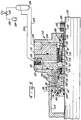
- Fig. 2 is a section taken along an axial, vertical plane of the seal of Fig. 1, on an enlarged scale.
- Fig. 3 is a front elevation view of a portion of a mating ring seal face, showing the spiral grooves.
- Fig. 4 is a schematic view of the barrier seal system, illustrating the buffer fluid supply arrangement.
- Fig. 5 is a section similar to Fig. 2 of an alternate embodiment of the invention.
- Fig. 6 is a diagrammatic detail section through a primary ring and a portion of a retainer, illustrating the double balance design of the primary ring. Cross hatching is omitted for clarity.
- Fig. 7 is an enlarged detail view in section of a buffer containment element.
- Fig. 8 is similar to Fig. 7, showing an alternate embodiment.
- Fig. 9 is similar to Fig. 7, showing another alternate embodiment.
- Figs. 1 and 2 illustrate a barrier seal system 10 according to the present invention.
- the seal system 10 seals the annular space between a rotating shaft 12 and a housing 14.
- the shaft 12 extends through a bore 16 in the housing 14.
- the housing 14 contains a high pressure fluid on the side of the seal labeled -Pressure- in Fig. 2.
- the exterior of the seal system is labeled -Atmosphere-.
- the specific seal shown is intended to contain a fluid in liquid form, the liquid being under pressure.
- a gland plate assembly 18 is bolted to the outer face of the housing.
- the gland plate has a boss 20 interfitting with the bore 16 to locate the gland plate.
- a gasket 22 prevents leakage between the bore 16 and gland plate 18.
- the gland plate has a set of upper, vertical and horizontal taps 24 and 26, respectively.
- An internal passage 28 is in fluid communication with the taps 24 and 26.
- a buffer fluid supply line from a reservoir connects to one of the taps.
- the threaded taps are provided in both the vertical and horizontal orientations to accommodate the most convenient physical connection of the supply line for a particular installation. Only one of the taps will be used, the other one will be plugged. Further, looking at Figs. 1 and 4, it can be seen that a similar lower set of vertical and horizontal taps 29, 31 is provided in the lower half of the gland plate. One of these taps is also used by a buffer fluid line connecting to the reservoir. Connections of the reservoir to the gland plate will be explained in further detail below.
- the seal system 10 has an elongated sleeve 36 surrounding the shaft 12.
- the sleeve extends from the exterior of the gland plate to a point well inside the bore 16 where it terminates at an integral flange 38.
- a seat is built into the flange to retain an O-ring 40, which prevents leakage between the sleeve and the shaft.
- At the exterior end of the sleeve there is a groove into which a snap ring 42 fits. The sleeve is held in place on the shaft by a plurality of set screws 44.
- the snap ring 42 retains an outboard seal shown generally at 46.
- the outboard seal is preferably a contacting mechanical end face seal.
- the outboard seal has a rotating seal head which includes a primary ring 48, held in place by a retainer 50.
- a static O-ring 52 prevents leakage between the retainer and sleeve.
- the seal head further includes a plurality of springs 54 engageable between the retainer and a drive ring 56.
- the seal head is completed by a secondary seal formed by O-ring 58.
- the springs 54 urge the primary ring 48 into engagement with the face of a mating ring 60.
- the mating ring is stationary as it is fixed to the gland plate by a plurality of pins 62.
- the mating ring is sealed to the gland plate by an O-ring 64.
- An inboard seal 66 is axially spaced from the outboard seal 46.
- the buffer chamber is in communication with the passage 28 in the gland plate so that buffer fluid is supplied to the buffer chamber from the reservoir.
- the inboard seal 66 has a stationary seal head including a retainer 70 which is pinned to the boss 20 of the gland plate.
- the retainer carries a plurality of springs 72 which urge a drive ring 74 into engagement with a primary ring 76.
- the drive ring has a plurality of tabs which engage depressions in the back face of the primary ring to rotationally lock the retainer and primary ring together.
- a secondary seal 78 is held between the retainer 70 and the primary ring 76.
- a disk 80 may also be positioned against a shoulder of the retainer to assist in holding the secondary seal in place against the process pressure.
- the primary ring has a plurality of axial passages or grooves 82 (Fig. 2) formed at its inside diameter.
- the grooves 82 facilitate movement of the buffer fluid through the buffer chamber 68 to the seal faces.
- the springs 72 urge the primary ring 76 into engagement with a mating ring 84.
- the mating ring is pinned to the flange 38 of the sleeve by pins 86.
- a static O-ring 88 prevents leakage between the flange 38 and the mating ring 84.
- the mating ring 84 has a radial seal face 90 on one side thereof.
- the other side of the mating ring may be termed a back face, which, in this case, includes radial and beveled surfaces 92.
- the primary ring 76 has a seal face 94 on one side and a back face on the other side which includes several radial surfaces. Details of the primary ring surfaces will be explained below.
- the mating ring face 90 has a plurality of spiral grooves 98 formed therein.
- the spiral grooves extend from the inside diameter of the seal face partially across the face.
- the ungrooved portion of the face forms a dam 100 which extends from the outside diameter of the grooved portion to the outside diameter of the mating ring.
- the face width is defined as half the difference between the inside and outside diameters of the face of the ring (primary or mating) having the smaller face outside diameter.
- the dam width is defined as the difference between the outside diameter of the primary ring and the outside diameter of the spiral grooves.
- the face width of the seal in Fig. 1 is 3,81mm (0.150 inches) and the dam width is 1,27mm (0.050").
- the spiral grooves have a depth of about 4,572mm (180 micro-inches).
- the grooves pick up buffer fluid from the buffer chamber and accelerate it against the dam 100, thereby increasing the pressure of the buffer fluid to a level greater than that of the process fluid in the housing. This prevents leakage of process fluid from the high pressure side of the seal to the buffer chamber. In fact, the rotating mating ring pumps some buffer fluid from the relatively low pressure buffer chamber to the high pressure side of the seal. This results in a small flow of buffer fluid into the process fluid.
- Fig. 4 illustrates how buffer fluid is supplied to make up for the losses caused by the pumping of the inboard seal.
- Fig. 4 illustrates a complete apparatus in schematic form.
- a motor 102 engages shaft 12 through a coupling 104.
- the shaft drives a pump 106, which includes housing 14 and bore 16.
- Barrier seal system 10 is shown in place in the bore.
- the upper horizontal tap 26 is shown connected to the buffer fluid reservoir 30 through a pipe or tube 108.
- the lower horizontal tap 31 also receives buffer fluid through a pipe 112.
- the supply reservoir has a float 32 connected to an auto-fill valve 34.
- the valve 34 is connectable to a buffer fluid supply line (not shown).
- One of the lines 108 or 112 may be finned to facilitate heat removal, while the other may be insulated to establish a thermal siphon.
- the thermal siphon is an optional feature which may be used to enhance the gravity feed of buffer fluid to the buffer chamber.
- Fig. 5 an alternate form of the barrier seal system is shown generally at 114.
- the seal system of Fig. 5 will withstand process pressures up to 96,46 bar or 98,433 Kp/cm (1400 psi) and temperatures of 1292°C (700°F).
- the gland plate 116 is bolted to a liner assembly 118; these parts are bolted to the housing 120.
- the liner has an elongated extension 122 which extends into the bore 124 of the housing.
- the liner is sealed to the housing by O-ring 126.
- the liner also has a buffer fluid outlet tap 128 in communication with a fluid passage 130.
- Gland plate 116 includes a similar tap 132 and passage 134. These may actually be in the lower half of the gland plate, but are shown in phantom for convenience.
- the seal system includes a sleeve 136 surrounding the shaft 138 and fastened thereto by a collar 140 held by set screws 142. O-rings 144 seal the sleeve against the shaft.
- the outboard seal includes a stationary mating ring 146 pinned to an extension portion of the gland plate 116.
- An O-ring 148 seals the mating ring 146 against the gland plate.
- the seal head includes a retainer 150 carrying springs 152 which contact a disk 154 and urge a primary ring 156 into engagement with the mating ring 146.
- a secondary seal 158 is held between the sleeve and primary ring.
- the retainer carries a pumping ring 160 which circulates buffer fluid from an outer buffer chamber 161 to an inner buffer chamber 163. These chambers are in communication with the passages 134 and 130, respectively.
- the inboard seal includes a mating ring 162 which is pinned to the flange of the sleeve 136.
- the mating ring has a seal face 164 on one side thereof.
- the seal face is similar to that shown in Fig. 3. Leakage between the mating ring and sleeve is prevented by a static seal 166.
- the seal head of the inboard seal includes a retainer 168 which is pinned to the liner assembly 118.
- Springs 170 act upon a disk 172 and the retainer 168 to urge a primary ring 174 into sealing engagement with the mating ring 162.
- a secondary seal 176 is disposed between the retainer and the primary ring.
- the primary ring has a radial seal face 178 opposite that of the mating ring.
- the primary ring also has an ear 180 engaging a notch 182 in the retainer.
- Buffer fluid is supplied to the inlet tap 132 through a line 184, which is connected to a reservoir 186.
- the reservoir is pressurized by a nitrogen bottle 188 connected to the reservoir through line 190 and pressure regulator 192. Buffer fluid returns to the reservoir from outlet tap 128 through return line 194.
- the nitrogen bottle pressurizes the buffer fluid and, in turn, the buffer chambers 161, 163 to about 13,77 bar or 14,06 kg/cm (200 psi).
- the buffer pressure is required to urge the buffer fluid into the spiral grooves of the inboard mating ring. Even with the pressurized buffer fluid, the pressure differential between the buffer fluid and process fluid may be on the order of 82,68 bar or 84,372 kg/cm (1200 psi).
- the primary ring may be made of tungsten carbide and the mating ring may be silicon carbide.
- Silicon carbide has a modulus of elasticity of 3,937 kg/cm x 106 (56 x 106 psi) while that of tungsten carbide is 6,258 x 106 kg/cm (89 x 106 psi). Thus, these materials will resist deflection under the process pressure.
- the modulus of carbon-graphite (a commonly-used seal ring material) can range from about 0,127 to 0,281 or 0,35 x 10⁶ kg/cm (1.8 to 4 or 5 x 10⁶ psi.) If low modulus materials are used for the rings, they become subject to deformation, which can distort the parallel arrangement of the seal faces. The seal faces must remain parallel to operate as intended. For purposes of this application, materials having a modulus of elasticity which is an order or magnitude greater than plain carbon will be termed high modulus materials.
- the primary ring has a cylindrical seat defined by an axial ledge 196 and a radial shoulder 198. There is also a notch having surfaces 200 and 202. The notch receives the end of the retainer 70.
- the front face of the primary ring includes the seal surface 94 and a front neutral surface 204.
- the back face of the primary ring includes shoulders 198 and 202 and a back neutral surface 206.
- the back neutral surface 206 is that portion of the back face which opposite the front neutral surface 204, i.e., the portion below dotted line 207. These faces are termed "neutral" because they cancel one another in the balance calculation, as will be explained.
- Line 207 also defines a smaller surface 208 between neutral surface 206 and the ledge 196.
- the retainer 70 has a notch defined by a radial shoulder 210 and an axial surface 212.
- These various components of the retainer and primary ring define a series of diameters, including an outside diameter D of the primary ring face, an internal pressurization balance diameter B, an external pressurization balance diameter b and an internal diameter of the seal face d.
- Seal balance relates to the axial forces on the primary ring due to the pressure of the process fluid. These forces, together with the spring force, determine how tightly the primary ring fits against the mating ring, thereby governing the gap between them, which, in turn, is an important factor in determining overall seal performance.
- the process fluid pressure will act on both sides of the primary ring. Since the pressure is acting on both the front and back sides of the primary ring, the ratio of the areas of those surfaces becomes critical.
- the seal balance therefore, is defined as the ratio of the area of the primary ring subject to a force which will close the primary ring against the mating ring to the area of the primary ring subject to forces which will open the gap between the primary ring and mating ring. In short, the seal balance is the area of closing divided by the area of opening.
- a pressure gradient will act on seal face 94, tending to open the seal gap.
- the static area of opening is simply the seal face 94, which is ⁇ (D - d) / 4.
- the area of closing depends on whether the seal is externally pressurized or internally pressurized. Consider first the case of internal pressurization. The process pressure is then located in the area designated with the letter A. The full process pressure will operate on front neutral surface 204, back neutral surface 206 and surface 208. Internal pressure will also force the secondary seal 78 against the radial shoulder 198, thereby effectively operating on a surface to the limit of the axial surface 212. Forces operating on the neutral surfaces 204 and 206 operate in opposite directions and effectively cancel each other. Thus, the area of closing becomes the area between the internal pressurization balance diameter B and the internal seal face diameter d. Thus, the area of closing equals ⁇ (B - d) / 4.
- the process pressure operates at the location indicated at B in Fig. 6.
- the pressure moves the O-ring 78 against the axial shoulder 210, thereby leaving the pressure to operate on faces 198 and 202.
- the area of closing for external pressurization becomes ⁇ (D - b) / 4.
- the static area of opening remains the same, namely, ⁇ (D - d) / 4.
- the balance for O.D. pressurization is (D - b) / (D - d). This is also chosen to be about .8.
- the balance for both the internal and external pressurization is the same. This is said to be a double balanced primary ring.
- Figs. 7-9 show three embodiments of a containment means located on the pressurized side of the seal faces and defining a containment chamber.
- the containment chamber retains buffer fluid pumped across the seal faces while preventing entrance of process fluid into the containment chamber. This is important because in pusher-type seals, such as in Figs. 1 and 5, the process fluid is exposed to the secondary seal. Fluid solidifying in the O-ring area of the secondary seal may eventually restrict primary ring movement, resulting in seal leakage as the faces hang open. While an internal flush may be provided to prevent this, the equipment required to do so is expensive.
- the containment means of Fig. 7 includes an enclosure or shell shown generally at 214.
- the shell 214 includes a generally cylindrical body portion 216 which integrally connected to a gasket 218 at one end.
- the gasket 218 is trapped between the gland plate 18 and housing 14. It can replace the gasket 22 of Fig. 1.
- a lip seal 220 which is in sliding engagement with the rotating flange 38 of the sleeve.
- the lip seal 220 is angled so as to restrict leakage from the process fluid side of the seal into the containment chamber 222. Buffer fluid pumped across the seal faces into the containment chamber 222 is permitted to flow from the containment chamber, past the lip seal and into the high pressure side of the seal.
- the shell 214 is preferably made of polytetrafluoroethylene.
- Fig. 8 shows an alternate embodiment wherein the containment means comprises a modified retainer 70A.
- the retainer has an extension portion 224 spanning the seal faces.
- Extension 224 has a seat which mounts a flexible seal 226. Seal 226 contacts the flange 38 of the rotating sleeve.
- a containment chamber is defined at 228.
- FIG. 9 A further alternate embodiment is shown in Fig. 9. It utilizes a generally cylindrical adaptor 230, which is press fit onto the retainer 70.
- a modified sleeve flange 38A has a threaded shoulder 232 on which a collar 234 is mounted.
- the collar 234 traps a lip seal 236 on the end of the flange 38A.
- the adaptor 230 and seal 236 define the containment chamber 238.
- the containment means of any of the embodiments of Figs. 7-9 creates a containment chamber so that a clean buffer fluid surrounds the O-ring area of the secondary seal.
- the containment chamber has a small enough volume so that the seal pumping rate can fill the containment chamber without requiring external filling.
- the lip seals function as check valves which seal product pressure while allowing buffer fluid to get past. Once the pump or other device starts operating, the containment chamber will fill with pumpage from the seal faces. When the containment chamber pressure overcomes the process pressure and the lip seal resistance, the buffer fluid will bleed past the lip into the process. This keeps the product away from the O-ring secondary seal area and will continually lubricate the lip seal in dynamic operation. Statically, the lip seal will actuate with O.D. pressure to prevent product intrusion.
Abstract
Description
- The invention relates to a seal system according to the preamble part of
claim 1. - A seal system is known from US-A-4 290 611 includes inboard and outboard seals, each having a primary and a mating ring. The space between the inboard and outboard seals defines a buffer chamber. Buffer fluid is supplied to the buffer chamber. The inward seal pumps buffer fluid across the seal faces towards the high pressure side of the seal when the shaft rotates. The pressurized buffer fluid originates from the high pressure side and can be supplied to the buffer chamber by a conduit containing a filter and a flow restrictor or by an external pump. The buffer fluid's pressure is equal to or less than the process fluid pressure at the high pressure side.
- E. Meyer, 'Mechanical Seals', 2nd Edition 1972, pages 176-179, ILIFFE Books, London, GB, discloses a dual face seal in a buffer chamber of a PVC - agitator housing. Buffer fluid is supplied to the buffer chamber from an external thermosyphon buffer pressure device. The pressure device contains a reservoir at an elevated position above the buffer chamber and a supply for pressurized gas to the reservoir. The inboard seal does not pump buffer fluid towards the high pressure side and, consequently, the buffer fluid is pressurized in excess of the pressure of the process fluid at the high pressure side.
- One of the objects of the invention is a seal system of the type as described in the preamble part of
claim 1 which reduces or eliminates the requirements for buffer fluid pressurizing, minimises potential emissions of process fluid, and simplifies the buffer fluid supply equipment. - The above-mentioned objects can be acheived with a seal system having the features of
claim 1. - The buffer fluid in the buffer chamber prevents the process fluid from contacting a secondary seal or the primary and mating ring seal faces of the inboard seal. The primary ring of the inboard seal can be arranged to be double balanced so that pressure reversals can be tolerated without loss of closing force. The buffer fluid may be gravity fed to the buffer chamber from the reservoir.
- Preferred embodiments are disclosed in dependent claims.
- Embodiments of the invention will be described on the basis of the enclosed drawings. In the drawings is:
- Fig. 1 is a perspective view, with portions cut away, of the barrier seal system according to the present invention.
- Fig. 2 is a section taken along an axial, vertical plane of the seal of Fig. 1, on an enlarged scale.
- Fig. 3 is a front elevation view of a portion of a mating ring seal face, showing the spiral grooves.
- Fig. 4 is a schematic view of the barrier seal system, illustrating the buffer fluid supply arrangement.
- Fig. 5 is a section similar to Fig. 2 of an alternate embodiment of the invention.
- Fig. 6 is a diagrammatic detail section through a primary ring and a portion of a retainer, illustrating the double balance design of the primary ring. Cross hatching is omitted for clarity.
- Fig. 7 is an enlarged detail view in section of a buffer containment element.
- Fig. 8 is similar to Fig. 7, showing an alternate embodiment.
- Fig. 9 is similar to Fig. 7, showing another alternate embodiment.
- Figs. 1 and 2 illustrate a
barrier seal system 10 according to the present invention. Theseal system 10 seals the annular space between arotating shaft 12 and ahousing 14. Theshaft 12 extends through abore 16 in thehousing 14. Thehousing 14 contains a high pressure fluid on the side of the seal labeled -Pressure- in Fig. 2. The exterior of the seal system is labeled -Atmosphere-. The specific seal shown is intended to contain a fluid in liquid form, the liquid being under pressure. - A
gland plate assembly 18 is bolted to the outer face of the housing. The gland plate has aboss 20 interfitting with thebore 16 to locate the gland plate. Agasket 22 prevents leakage between thebore 16 andgland plate 18. - The gland plate has a set of upper, vertical and
horizontal taps internal passage 28 is in fluid communication with thetaps horizontal taps - The
seal system 10 has an elongatedsleeve 36 surrounding theshaft 12. The sleeve extends from the exterior of the gland plate to a point well inside thebore 16 where it terminates at anintegral flange 38. A seat is built into the flange to retain an O-ring 40, which prevents leakage between the sleeve and the shaft. At the exterior end of the sleeve there is a groove into which asnap ring 42 fits. The sleeve is held in place on the shaft by a plurality of set screws 44. - The
snap ring 42 retains an outboard seal shown generally at 46. The outboard seal is preferably a contacting mechanical end face seal. The outboard seal has a rotating seal head which includes aprimary ring 48, held in place by aretainer 50. A static O-ring 52 prevents leakage between the retainer and sleeve. The seal head further includes a plurality ofsprings 54 engageable between the retainer and adrive ring 56. The seal head is completed by a secondary seal formed by O-ring 58. - The
springs 54 urge theprimary ring 48 into engagement with the face of amating ring 60. The mating ring is stationary as it is fixed to the gland plate by a plurality ofpins 62. The mating ring is sealed to the gland plate by an O-ring 64. - An
inboard seal 66 is axially spaced from theoutboard seal 46. The inboard andoutboard seals sleeve 36 andgland plate 18, define abuffer chamber 68. The buffer chamber is in communication with thepassage 28 in the gland plate so that buffer fluid is supplied to the buffer chamber from the reservoir. - Looking now at the details of the
inboard seal 66, it has a stationary seal head including aretainer 70 which is pinned to theboss 20 of the gland plate. The retainer carries a plurality ofsprings 72 which urge adrive ring 74 into engagement with aprimary ring 76. The drive ring has a plurality of tabs which engage depressions in the back face of the primary ring to rotationally lock the retainer and primary ring together. Asecondary seal 78 is held between theretainer 70 and theprimary ring 76. Adisk 80 may also be positioned against a shoulder of the retainer to assist in holding the secondary seal in place against the process pressure. - The primary ring has a plurality of axial passages or grooves 82 (Fig. 2) formed at its inside diameter. The
grooves 82 facilitate movement of the buffer fluid through thebuffer chamber 68 to the seal faces. - The
springs 72 urge theprimary ring 76 into engagement with amating ring 84. The mating ring is pinned to theflange 38 of the sleeve by pins 86. A static O-ring 88 prevents leakage between theflange 38 and themating ring 84. - The
mating ring 84 has a radial seal face 90 on one side thereof. The other side of the mating ring may be termed a back face, which, in this case, includes radial and beveled surfaces 92. Similarly, theprimary ring 76 has aseal face 94 on one side and a back face on the other side which includes several radial surfaces. Details of the primary ring surfaces will be explained below. - Details of the mating ring's seal face are shown in Fig. 3. The
mating ring face 90 has a plurality ofspiral grooves 98 formed therein. The spiral grooves extend from the inside diameter of the seal face partially across the face. The ungrooved portion of the face forms adam 100 which extends from the outside diameter of the grooved portion to the outside diameter of the mating ring. The face width is defined as half the difference between the inside and outside diameters of the face of the ring (primary or mating) having the smaller face outside diameter. The dam width is defined as the difference between the outside diameter of the primary ring and the outside diameter of the spiral grooves. For reference purposes only, the face width of the seal in Fig. 1 is 3,81mm (0.150 inches) and the dam width is 1,27mm (0.050"). The spiral grooves have a depth of about 4,572mm (180 micro-inches). - The grooves pick up buffer fluid from the buffer chamber and accelerate it against the
dam 100, thereby increasing the pressure of the buffer fluid to a level greater than that of the process fluid in the housing. This prevents leakage of process fluid from the high pressure side of the seal to the buffer chamber. In fact, the rotating mating ring pumps some buffer fluid from the relatively low pressure buffer chamber to the high pressure side of the seal. This results in a small flow of buffer fluid into the process fluid. - Fig. 4 illustrates how buffer fluid is supplied to make up for the losses caused by the pumping of the inboard seal. Fig. 4 illustrates a complete apparatus in schematic form. A
motor 102 engagesshaft 12 through acoupling 104. The shaft drives apump 106, which includeshousing 14 and bore 16.Barrier seal system 10 is shown in place in the bore. The upperhorizontal tap 26 is shown connected to thebuffer fluid reservoir 30 through a pipe ortube 108. The lowerhorizontal tap 31 also receives buffer fluid through apipe 112. The supply reservoir has afloat 32 connected to an auto-fill valve 34. Thevalve 34 is connectable to a buffer fluid supply line (not shown). One of thelines - Turning now to Fig. 5, an alternate form of the barrier seal system is shown generally at 114. This embodiment is intended for use in high pressure, high temperature applications. The seal system of Fig. 5 will withstand process pressures up to 96,46 bar or 98,433 Kp/cm (1400 psi) and temperatures of 1292°C (700°F). In this embodiment the gland plate 116 is bolted to a
liner assembly 118; these parts are bolted to thehousing 120. The liner has anelongated extension 122 which extends into thebore 124 of the housing. The liner is sealed to the housing by O-ring 126. The liner also has a buffer fluid outlet tap 128 in communication with afluid passage 130. Gland plate 116 includes asimilar tap 132 andpassage 134. These may actually be in the lower half of the gland plate, but are shown in phantom for convenience. - The seal system includes a
sleeve 136 surrounding theshaft 138 and fastened thereto by acollar 140 held by setscrews 142. O-rings 144 seal the sleeve against the shaft. - The outboard seal includes a
stationary mating ring 146 pinned to an extension portion of the gland plate 116. An O-ring 148 seals themating ring 146 against the gland plate. - The seal head includes a
retainer 150 carryingsprings 152 which contact adisk 154 and urge aprimary ring 156 into engagement with themating ring 146. Asecondary seal 158 is held between the sleeve and primary ring. The retainer carries apumping ring 160 which circulates buffer fluid from anouter buffer chamber 161 to aninner buffer chamber 163. These chambers are in communication with thepassages - The inboard seal includes a
mating ring 162 which is pinned to the flange of thesleeve 136. The mating ring has aseal face 164 on one side thereof. The seal face is similar to that shown in Fig. 3. Leakage between the mating ring and sleeve is prevented by astatic seal 166. - The seal head of the inboard seal includes a
retainer 168 which is pinned to theliner assembly 118.Springs 170 act upon adisk 172 and theretainer 168 to urge aprimary ring 174 into sealing engagement with themating ring 162. Asecondary seal 176 is disposed between the retainer and the primary ring. The primary ring has aradial seal face 178 opposite that of the mating ring. The primary ring also has anear 180 engaging anotch 182 in the retainer. - Buffer fluid is supplied to the
inlet tap 132 through aline 184, which is connected to areservoir 186. The reservoir is pressurized by a nitrogen bottle 188 connected to the reservoir throughline 190 andpressure regulator 192. Buffer fluid returns to the reservoir from outlet tap 128 through return line 194. The nitrogen bottle pressurizes the buffer fluid and, in turn, thebuffer chambers - Another feature of the seal of Fig. 5 is the use of high strength materials for both the primary ring and mating ring of the inboard seal. For example, the primary ring may be made of tungsten carbide and the mating ring may be silicon carbide. Silicon carbide has a modulus of elasticity of 3,937 kg/cm x 10⁶ (56 x 10⁶ psi) while that of tungsten carbide is 6,258 x 10⁶ kg/cm (89 x 10⁶ psi). Thus, these materials will resist deflection under the process pressure. For purposes of comparison, the modulus of carbon-graphite (a commonly-used seal ring material) can range from about 0,127 to 0,281 or 0,35 x 10⁶ kg/cm (1.8 to 4 or 5 x 10⁶ psi.) If low modulus materials are used for the rings, they become subject to deformation, which can distort the parallel arrangement of the seal faces. The seal faces must remain parallel to operate as intended. For purposes of this application, materials having a modulus of elasticity which is an order or magnitude greater than plain carbon will be termed high modulus materials.
- It will be noted that the embodiments of both Figs. 1 and 5 are arranged such that the process pressure is present at the outside diameters of the seal rings. This is referred to as an O.D. pressurized seal. While O.D. pressurization is shown and preferred, it will be understood that an I.D. pressurized arrangement could be used with the present invention. An advantage of O.D. pressurization is the centrifugal force generated by the rotating seal member on the process fluid tends to project the fluid away from the seal faces. This helps prevent contamination of the seal faces, particularly by particulates that may be carried in the process fluid.
- It has been noted above that the inboard seals in the embodiments of both Figs. 1 and 5 are double balanced. The meaning and significance of this will be explained in conjunction with Fig. 6. Several details of the primary ring and retainer are shown in Fig. 6. The primary ring has a cylindrical seat defined by an axial ledge 196 and a
radial shoulder 198. There is also anotch having surfaces retainer 70. - The front face of the primary ring includes the
seal surface 94 and a frontneutral surface 204. The back face of the primary ring includesshoulders neutral surface 206. The backneutral surface 206 is that portion of the back face which opposite the frontneutral surface 204, i.e., the portion below dottedline 207. These faces are termed "neutral" because they cancel one another in the balance calculation, as will be explained.Line 207 also defines a smaller surface 208 betweenneutral surface 206 and the ledge 196. - The
retainer 70 has a notch defined by a radial shoulder 210 and anaxial surface 212. - These various components of the retainer and primary ring define a series of diameters, including an outside diameter D of the primary ring face, an internal pressurization balance diameter B, an external pressurization balance diameter b and an internal diameter of the seal face d.
- Seal balance relates to the axial forces on the primary ring due to the pressure of the process fluid. These forces, together with the spring force, determine how tightly the primary ring fits against the mating ring, thereby governing the gap between them, which, in turn, is an important factor in determining overall seal performance. The process fluid pressure will act on both sides of the primary ring. Since the pressure is acting on both the front and back sides of the primary ring, the ratio of the areas of those surfaces becomes critical. The seal balance, therefore, is defined as the ratio of the area of the primary ring subject to a force which will close the primary ring against the mating ring to the area of the primary ring subject to forces which will open the gap between the primary ring and mating ring. In short, the seal balance is the area of closing divided by the area of opening.
- Looking specifically at Fig. 6, a pressure gradient will act on
seal face 94, tending to open the seal gap. Thus, the static area of opening is simply theseal face 94, which is π (D - d) / 4. - The area of closing depends on whether the seal is externally pressurized or internally pressurized. Consider first the case of internal pressurization. The process pressure is then located in the area designated with the letter A. The full process pressure will operate on front
neutral surface 204, backneutral surface 206 and surface 208. Internal pressure will also force thesecondary seal 78 against theradial shoulder 198, thereby effectively operating on a surface to the limit of theaxial surface 212. Forces operating on theneutral surfaces - Considering the case of external pressurization or O.D. pressurization, the process pressure operates at the location indicated at B in Fig. 6. The pressure moves the O-
ring 78 against the axial shoulder 210, thereby leaving the pressure to operate onfaces - It will be noted that the physical arrangement that brings about double balancing in this case is that the internal and external balance diameters B, b are symmetrical about the centerline c of the primary
ring seal face 94. As a result, the area of closing for internal pressurization approximately equals the area of closing for external pressurization. Consequently, of course, the balance figures for both cases are the same and the seal is said to be double balanced. With double balancing the seal has the same balance whether the primary ring sees internal pressure or external pressure. This is important because if for some reason the internal seal stopped pumping, it could still function as a contacting seal. Also, in arrangements such as Fig. 5 where there is some buffer pressure, a double balanced seal can withstand pressure reversals. That is, ordinarily the seal of Fig. 5 expects to have O.D. pressurization from the process fluid. If, for some reason, the process fluid pressure drops below that of the buffer chamber, the seal would become internally pressurized. If the seal were not double balanced, it would blow open upon the occurrence of such a pressure reversal. - Turning now to another aspect of the invention, Figs. 7-9 show three embodiments of a containment means located on the pressurized side of the seal faces and defining a containment chamber. The containment chamber retains buffer fluid pumped across the seal faces while preventing entrance of process fluid into the containment chamber. This is important because in pusher-type seals, such as in Figs. 1 and 5, the process fluid is exposed to the secondary seal. Fluid solidifying in the O-ring area of the secondary seal may eventually restrict primary ring movement, resulting in seal leakage as the faces hang open. While an internal flush may be provided to prevent this, the equipment required to do so is expensive. It also results in flush flow in the range of 3,785 to 7,57 l/min (1 to 2 gallons per minute,) which is added to the process fluid. In many instances, this product dilution rate is unacceptable. The containment means of Figs. 7-9 solve these problems. In Figs. 7-9, parts having little or no modification from the form of Figs. 1 and 2 are given the same reference numerals.
- The containment means of Fig. 7 includes an enclosure or shell shown generally at 214. The shell 214 includes a generally
cylindrical body portion 216 which integrally connected to agasket 218 at one end. Thegasket 218 is trapped between thegland plate 18 andhousing 14. It can replace thegasket 22 of Fig. 1. At the opposite end of the shell 214 is alip seal 220 which is in sliding engagement with the rotatingflange 38 of the sleeve. Together the shell 214,sleeve flange 38,mating ring 84,primary ring 76 andretainer 70 define a containment chamber 222. Thelip seal 220 is angled so as to restrict leakage from the process fluid side of the seal into the containment chamber 222. Buffer fluid pumped across the seal faces into the containment chamber 222 is permitted to flow from the containment chamber, past the lip seal and into the high pressure side of the seal. The shell 214 is preferably made of polytetrafluoroethylene. - Fig. 8 shows an alternate embodiment wherein the containment means comprises a modified retainer 70A. The retainer has an extension portion 224 spanning the seal faces. Extension 224 has a seat which mounts a
flexible seal 226.Seal 226 contacts theflange 38 of the rotating sleeve. A containment chamber is defined at 228. - A further alternate embodiment is shown in Fig. 9. It utilizes a generally cylindrical adaptor 230, which is press fit onto the
retainer 70. A modifiedsleeve flange 38A has a threadedshoulder 232 on which acollar 234 is mounted. Thecollar 234 traps alip seal 236 on the end of theflange 38A. The adaptor 230 and seal 236 define thecontainment chamber 238. - The containment means of any of the embodiments of Figs. 7-9 creates a containment chamber so that a clean buffer fluid surrounds the O-ring area of the secondary seal. The containment chamber has a small enough volume so that the seal pumping rate can fill the containment chamber without requiring external filling. The lip seals function as check valves which seal product pressure while allowing buffer fluid to get past. Once the pump or other device starts operating, the containment chamber will fill with pumpage from the seal faces. When the containment chamber pressure overcomes the process pressure and the lip seal resistance, the buffer fluid will bleed past the lip into the process. This keeps the product away from the O-ring secondary seal area and will continually lubricate the lip seal in dynamic operation. Statically, the lip seal will actuate with O.D. pressure to prevent product intrusion.
Claims (15)
- A seal system (10, 114) for sealing the annular space between a housing (14, 120) and a rotating shaft (12, 138) extending through a bore (16, 124) in the housing, the housing containing a high pressure fluid, the seal system (10, 114) comprising:a gland plate (18, 116) connectable to the housing (14, 120);an outboard seal (46) having a first portion (60, 146) connected to the gland plate (18, 116) or the housing (14, 120) and a second portion (48, 156) connectable for rotation with the shaft (12, 138);an inboard seal (66) at least a portion of which is mounted in the annular space, the seal (66) having a mating ring (84, 162) and a primary ring (76, 174), one of which is mounted for rotation with the shaft (12, 138) and the other of which is fixedly connected to the gland plate (18, 116) or the housing (14, 120) the mating and primary rings (76, 84, 162, 174), having opposed radial seal faces (90, 94, 164, 178) on one side thereof and back faces on the other side thereof, the inboard seal (66) being positioned axially of the outboard seal (46) to define a buffer chamber (68, 161, 163); andmeans (98) incorporated into said inboard seal (66) for pumping a fluid from the buffer chamber (68, 161, 163) towards the inboard high pressure side of the inboard seal (66) in opposition to fluid leakage from said high pressure side, characterized bya buffer fluid reservoir (30, 186) located externally of the housing (14, 120) in fluid communication with the buffer chamber (68, 161, 163) so as to supply buffer fluid thereto; andby means for pressurizing said buffer fluid in said reservoir (30, 186) separate and removed from the means (98) incorporated in said inboard seal (66) for pumping said fluid.
- Seal system of claim 1, characterized in thatthe ring (76, 174) of the inboard seal (66) being closest to the buffer chamber (68, 161, 163) has axial grooves (82) formed therein to enhance buffer fluid flow from the back face of the ring (76, 174) to the seal face (94, 178).
- Seal system of claim 1, characterized in thatthe means for pressurizing the buffer fluid comprises the buffer fluid reservoir (30) being located at a greater elevation than the buffer chamber (68) so as to supply buffer fluid thereto under gravity feed.
- Seal system of claim 3 characterized bya float valve (34) attached to the reservoir (30) and connectable to a fluid supply line for automatically refilling the reservoir (30) when the buffer fluid therein reaches a predetermined level.
- Seal system of claim 3, characterized in thatthe fluid communication between the reservoir (30) and the buffer chamber (68) includes lines (108, 112) forming a thermal loop.
- Seal system of claim 5, characterized in that one of the lines (108, 112) is finned and the other of the lines is insulated to enhance a thermal syphon effect.
- Seal system as in claim 1, characterized bya sleeve (36, 136) mounted on the shaft (12, 138) for rotation therewith, the outboard seal second portion (48, 156) being connected to the sleeve (36, 136) for rotation with the shaft (12, 138);the inboard seal (66) having a retainer (70, 168) fixed to the gland plate (18) or the housing (120) and at least partially enclosing the primary ring (76, 174) to fix the radial position while allowing axial movement of the primary ring (76, 174); andby a secondary seal (78, 176) being disposed between the retainer (70, 168) and the primary ring (76, 174).
- Seal system of claim 7, characterized in thatin the inboard seal (66), the seal face (94, 178) and the back face of the primary ring (76, 174), the retainer (70, 168) and the secondary seal (78, 176) being shaped and arranged such that the primary ring (76, 174) is double balanced with a ratio of about 0.8 between the area of closing and the area of opening the inboard seal (66), said respective areas being exposed to the high pressure at the high pressure side and to the buffer fluid pressure in the buffer chamber (68, 161, 163).
- Seal system of claim 8, characterized in thatthe inboard seal primary ring (76) comprises a back face with a first seat having an axial ledge (196) and a radial shoulder (198),that a second seat having an axial ledge (212) and a radial shoulder (210) is formed in the retainer (70) opposite said first seat,that the diameters (b, B) of said ledges (196, 212) being symmetric about the centre line (C) of the primary ring seal face (94),and that the secondary seal (78) is disposed between said axial ledges (212, 196).
- Seal system of claim 1, characterized in thatthe inboard seal primary ring (76, 174) is made of tungsten carbide and that the mating ring (84, 162) is made of silicon carbide.
- Seal system of claim 1, characterized in thatthe means for pumping the buffer fluid comprises a circumferential dam (100) on one of the primary or mating ring seal faces (90, 94, 164, 178) on the high pressure side of said seal faces, and a plurality of spiral grooves (98) extending from the dam (100) to the low pressure buffer chamber (68, 161, 163) for pumping fluid from the buffer chamber (68, 161, 163) towards the high pressure side.
- Seal system of claim 11, characterized in thatthe primary ring face (94, 178) width is about 7.92 mm (0.312 in) and that the dam (100) width is about 2.36 mm (0.093 in).
- Seal system of claim 1, characterized in thatthe means for pressurizing the buffer fluid in the reservoir (186) comprises an externally located nitrogen bottle (188) containing nitrogen gas under pressure.
- Seal system of any of the previous claims, characterized in thatthe outer diameters of the inboard seal primary and mating rings (76, 84, 174, 162) are exposed to the fluid under high pressure in the housing (14, 120).
- Seal system of claim 1, characterized in thatthe outboard seal (46) comprises a mating ring (60, 146) and axially moveable primary ring (48, 156), one of which is mounted for rotation with the shaft (12, 138), the other of which is fixedly connected to the housing (14, 120),that a retainer (50, 150) at least partially encloses the primary ring (48, 156),that a secondary seal (58, 158) is disposed between the retainer (50, 150) and the primary ring (48, 156),and that means (54, 152) are provided for biasing the axially moveable primary ring (48, 156) against the mating ring (60, 146).
Applications Claiming Priority (2)
| Application Number | Priority Date | Filing Date | Title |
|---|---|---|---|
| US07/491,980 US5249812A (en) | 1990-03-12 | 1990-03-12 | Barrier seal systems |
| US491980 | 1990-03-12 |
Publications (3)
| Publication Number | Publication Date |
|---|---|
| EP0447898A2 EP0447898A2 (en) | 1991-09-25 |
| EP0447898A3 EP0447898A3 (en) | 1991-10-02 |
| EP0447898B1 true EP0447898B1 (en) | 1996-02-07 |
Family
ID=23954461
Family Applications (1)
| Application Number | Title | Priority Date | Filing Date |
|---|---|---|---|
| EP91103622A Expired - Lifetime EP0447898B1 (en) | 1990-03-12 | 1991-03-08 | Improvements in barrier seal systems |
Country Status (12)
| Country | Link |
|---|---|
| US (2) | US5249812A (en) |
| EP (1) | EP0447898B1 (en) |
| JP (1) | JPH0533871A (en) |
| KR (1) | KR910017109A (en) |
| CN (1) | CN1024587C (en) |
| AT (1) | ATE134029T1 (en) |
| AU (1) | AU637462B2 (en) |
| BR (1) | BR9100980A (en) |
| CA (1) | CA2037966A1 (en) |
| DE (1) | DE69116906T2 (en) |
| IE (1) | IE75222B1 (en) |
| ZA (1) | ZA911769B (en) |
Families Citing this family (85)
| Publication number | Priority date | Publication date | Assignee | Title |
|---|---|---|---|---|
| CA2096759A1 (en) * | 1992-08-06 | 1994-02-07 | Mark G. Pospisil | Mechanical end face seal system |
| US5375853B1 (en) * | 1992-09-18 | 1998-05-05 | Crane John Inc | Gas lubricated barrier seal |
| US5468002A (en) * | 1993-10-25 | 1995-11-21 | John Crane Inc. | Mechanical end face seal having an improved mating ring |
| US5490679A (en) * | 1993-12-20 | 1996-02-13 | John Crane Inc. | Seal ring design |
| US5529315A (en) * | 1994-02-14 | 1996-06-25 | John Crane Inc. | Tandem seal arrangement for mechanical face seals |
| US5494299A (en) * | 1994-02-22 | 1996-02-27 | Evironamics Corporation | Temperature and pressure resistant rotating seal construction for a pump |
| CA2193482C (en) * | 1994-06-20 | 2002-08-20 | Thomas W. Ramsay | Seal/bearing assembly |
| US5746435A (en) * | 1994-09-30 | 1998-05-05 | Arbuckle; Donald P. | Dual seal barrier fluid leakage control method |
| US5733253A (en) * | 1994-10-13 | 1998-03-31 | Transfusion Technologies Corporation | Fluid separation system |
| US5562406A (en) * | 1995-01-11 | 1996-10-08 | Ansimag Inc. | Seal assembly for fluid pumps and method for detecting leaks in fluid pumps or fluid containment devices |
| US5553867A (en) * | 1995-04-21 | 1996-09-10 | Environamics Corporation | Triple cartridge seal having one inboard and two concentric seals for chemical processing pump |
| US5636847A (en) * | 1995-09-13 | 1997-06-10 | Chesterton International Company | Dual face seal clean barrier fluid and dynamic pressure control system |
| US6070880A (en) * | 1996-02-02 | 2000-06-06 | Sealtec Mck Limited | System for lubricating mechanical seals |
| US5941532A (en) | 1996-06-20 | 1999-08-24 | Rexnord Corporation | Aerospace housing and shaft assembly with noncontacting seal |
| JPH10292868A (en) * | 1997-04-18 | 1998-11-04 | Honda Motor Co Ltd | Shaft seal mechanism of liquid pump |
| US6068264A (en) * | 1997-12-17 | 2000-05-30 | A.W. Chesterton Company | Split mechanical face seal with negative pressure control system |
| US6120034A (en) | 1997-12-17 | 2000-09-19 | A.W. Chesterston Company | Secondary sealing assembly for mechanical face seal |
| DE29806905U1 (en) | 1998-04-16 | 1998-07-09 | Burgmann Dichtungswerk Feodor | Mechanical seal arrangement, in particular for liquid gas sealing |
| SE520864C2 (en) * | 1998-05-04 | 2003-09-09 | Roplan Ab | Mechanical sealing device, especially for pumps |
| ATE323857T1 (en) * | 1998-08-17 | 2006-05-15 | Donald Philip Arbuckle | INTEGRATED SEALING PROTECTION DEVICE AGAINST LIQUIDS WITH VISUAL VOLUME INDICATOR |
| US6428011B1 (en) * | 1998-09-16 | 2002-08-06 | Aes Engineering Limited | Mechanical seals |
| AU3052399A (en) * | 1999-03-29 | 2000-10-16 | Unitor Ltd. | Arrangement for sealing a pump shaft |
| GB0004239D0 (en) * | 2000-02-24 | 2000-04-12 | Crane John Uk Ltd | Seal assemblies |
| US6454523B1 (en) * | 2000-07-17 | 2002-09-24 | California Acrylic Industries | Spa with double sealed pump |
| US6379127B1 (en) * | 2000-09-29 | 2002-04-30 | Lawrence Pumps, Inc. | Submersible motor with shaft seals |
| US6454268B1 (en) * | 2001-02-09 | 2002-09-24 | Eagle Industry Co., Ltd. | Shaft seal device |
| US6655693B2 (en) * | 2001-04-26 | 2003-12-02 | John Crane Inc. | Non-contacting gas compressor seal |
| US6789804B2 (en) | 2001-07-23 | 2004-09-14 | Kaydon Corporation | Dry gas shutdown seal |
| GB0126105D0 (en) * | 2001-10-31 | 2002-01-02 | Aes Eng Ltd | Seal support systems - auto refill device |
| JP3933469B2 (en) * | 2001-12-28 | 2007-06-20 | イーグル工業株式会社 | Mechanical seal device |
| US6783322B2 (en) * | 2002-04-23 | 2004-08-31 | Roper Holdings, Inc. | Pump system with variable-pressure seal |
| GB0214636D0 (en) * | 2002-06-22 | 2002-08-07 | Aes Eng Ltd | A low cost mechanical seal |
| DE20214529U1 (en) * | 2002-09-19 | 2003-07-03 | Burgmann Dichtungswerke Gmbh | Double-acting sealing arrangements |
| HUE047968T2 (en) * | 2003-02-28 | 2020-05-28 | Chesterton A W Co | Balanced mechanical seal assembly |
| US7118114B2 (en) * | 2003-05-15 | 2006-10-10 | Woodward Governor Company | Dynamic sealing arrangement for movable shaft |
| US20060216177A1 (en) * | 2003-07-04 | 2006-09-28 | Warren Leslie J | Liquid pump and method for pumping a liquid that may have gas coming out of solution |
| GB0402887D0 (en) * | 2004-02-10 | 2004-03-17 | Aesseal Plc | Applications for controlling liquid flow through a seal when using a forced circulation barrier fluid suppport system |
| EP1602865A1 (en) * | 2004-06-02 | 2005-12-07 | Eagle Euroseals GmbH | Mechanical seal with cooled barrier medium |
| ZA200507096B (en) * | 2004-09-07 | 2006-06-28 | Crane John Inc | Sealing system for slurry pump |
| US7290561B2 (en) * | 2004-12-16 | 2007-11-06 | Diversified Dynamics Corporation | Pulsation causing valve for a plural piston pump |
| US7278443B2 (en) * | 2004-12-16 | 2007-10-09 | Diversified Dynamics Corporation | Pulsation causing valve for a plural piston pump |
| US20060140778A1 (en) * | 2004-12-28 | 2006-06-29 | Warren Leslie J | Reciprocating positive displacement pump for deionized water and method of cooling and lubricating therefor |
| GB0506096D0 (en) * | 2005-03-24 | 2005-05-04 | Aesseal Plc | Automatic and timed flushing of liquid in a system supporting a mechanical seal |
| US20060239834A1 (en) * | 2005-04-20 | 2006-10-26 | Larson Steve A | Metered pulse pump |
| SE531613C2 (en) * | 2005-06-27 | 2009-06-09 | Huhnseal Ab | sealing device |
| US20070073328A1 (en) * | 2005-09-26 | 2007-03-29 | Wilson-Cook Medical Inc., | Incrementally expandable balloon |
| KR100666787B1 (en) | 2005-11-03 | 2007-01-09 | 현대자동차주식회사 | Manufacturing method of mechanical seal of water pump for fuel cell |
| US20070120084A1 (en) * | 2005-11-29 | 2007-05-31 | Stumbo Steven C | Fully independent, redundant fluid energized sealing solution with secondary containment |
| US7426936B2 (en) * | 2005-11-29 | 2008-09-23 | Woodward Governor Company | Fully independent, redundant fluid energized sealing solution with secondary containment |
| US7415937B2 (en) * | 2006-10-27 | 2008-08-26 | Honeywell International Inc. | Self-contained sea water linear actuator |
| US8511219B2 (en) * | 2007-03-28 | 2013-08-20 | Clyde Union Inc. | Zero emissions reciprocating pump |
| US7784395B2 (en) * | 2007-03-28 | 2010-08-31 | Clyde Union Inc. | Zero emissions reciprocating pump |
| SE531210C2 (en) * | 2007-05-07 | 2009-01-20 | Roplan Internat Ab | Mechanical sealing device and pump |
| US7854584B2 (en) * | 2007-05-24 | 2010-12-21 | General Electric Company | Barrier sealing system for centrifugal compressors |
| TW201043814A (en) * | 2009-06-05 | 2010-12-16 | Scenic Precise Element Inc | Shaft seal |
| US8663454B2 (en) * | 2009-10-23 | 2014-03-04 | Chevron U.S.A. Inc. | Formulating a sealant fluid using gas to liquid base stocks |
| TWI404876B (en) * | 2009-12-31 | 2013-08-11 | Scenic Precise Element Inc | Shaft seal with protective effect |
| CN102147011B (en) * | 2010-02-08 | 2015-08-26 | 祥景精机股份有限公司 | The shaft seal of tool protective action |
| CN102192328A (en) * | 2010-03-12 | 2011-09-21 | 祥景精机股份有限公司 | Container-type shaft seal |
| JP5554749B2 (en) * | 2011-05-18 | 2014-07-23 | 日本ピラー工業株式会社 | Mechanical seal device for high pressure fluid |
| DE102011111697A1 (en) * | 2011-08-24 | 2013-02-28 | Eagleburgmann Germany Gmbh & Co. Kg | Cooled mechanical seal arrangement |
| US20140326440A1 (en) * | 2011-11-11 | 2014-11-06 | Eiquiperol - Indústria e Comércio de Equipamentos Mecânicos, Lda | Internal cooling system for mechanical seals and use thereof |
| WO2014042085A1 (en) * | 2012-09-11 | 2014-03-20 | イーグル工業株式会社 | Mechanical seal |
| CN102900846A (en) * | 2012-11-01 | 2013-01-30 | 安徽亚兰密封件有限公司 | Novel sealing device combining Archimedes spiral groove sealing and contact type mechanical sealing |
| CN105026761B (en) | 2012-12-31 | 2017-06-06 | 冷王公司 | Apparatus and method for extending the service life of the axle envelope of the compressor of open-drive |
| US8888105B1 (en) | 2013-05-29 | 2014-11-18 | Stephen J. Andrews | Mechanical seal system |
| EP3017291A4 (en) * | 2013-07-03 | 2017-01-25 | Wyatt Technology Corporation | Method and apparatus to control sample carryover in analytical instruments |
| GB201403619D0 (en) * | 2014-02-28 | 2014-04-16 | A E S Engineering Ltd | System for increasing the available gas buffer in seal support systems |
| DE202014103019U1 (en) * | 2014-07-02 | 2015-10-08 | Brinkmann Pumpen K.H. Brinkmann Gmbh & Co. Kg | Sealing arrangement on a pump shaft |
| US10036399B2 (en) * | 2014-08-29 | 2018-07-31 | VP Sales and Company, LP | Mechanical seal lubrication system |
| GB201419795D0 (en) * | 2014-11-06 | 2014-12-24 | Aes Eng Ltd | Mechanical seal support system |
| WO2017082158A1 (en) * | 2015-11-09 | 2017-05-18 | イーグル工業株式会社 | Mechanical seal |
| DE102016200818B4 (en) * | 2016-01-21 | 2020-09-10 | Eagleburgmann Germany Gmbh & Co. Kg | Mechanical seal arrangement with reduced leakage |
| US11796064B2 (en) | 2016-06-10 | 2023-10-24 | John Crane Uk Limited | Reduced emission gas seal |
| EP4141297A1 (en) * | 2016-06-10 | 2023-03-01 | John Crane UK Limited | Reduced emission gas seal |
| PL3558211T3 (en) | 2016-12-23 | 2023-10-02 | R.P. Scherer Technologies, Llc | Multiple-fill/chamber softgel die |
| GB201702893D0 (en) * | 2017-02-23 | 2017-04-12 | Aes Eng Ltd | Mechanical seal |
| FR3064029B1 (en) * | 2017-03-15 | 2021-04-30 | Safran Aircraft Engines | AIR-FIRE SEAL AND ASSEMBLY INCLUDING SUCH A SEAL |
| EP3752738A4 (en) * | 2018-02-14 | 2021-11-17 | Ceco Environmental IP Inc. | Tandem seal pump |
| CN108468810A (en) * | 2018-05-18 | 2018-08-31 | 四川日机密封件股份有限公司 | The enhanced non-contact mechanical seal structure of liquid |
| DE102019203454B3 (en) * | 2019-03-14 | 2020-07-09 | Eagleburgmann Germany Gmbh & Co. Kg | Marine mechanical seal assembly |
| CN110370483A (en) * | 2019-08-27 | 2019-10-25 | 青岛科技大学 | A kind of closed-smelting machine rotor sealing structure |
| KR102144916B1 (en) * | 2020-05-19 | 2020-08-14 | 주식회사 케이. 씨. 이 | Water Cooling system for mechanicalseal |
| CN111692340B (en) * | 2020-06-12 | 2022-03-22 | 东台市岳东橡胶密封件厂 | Built-in floating telescopic sealing element |
| RU204982U1 (en) * | 2021-03-23 | 2021-06-22 | Акционерное общество (АО) "Научно-исследовательский институт "Лопастных машин" ("НИИ ЛМ") | FLAT CONNECTOR SEAL FIXED TOGETHER BODY PARTS TO FORM A SEALING CAVITY |
Family Cites Families (18)
| Publication number | Priority date | Publication date | Assignee | Title |
|---|---|---|---|---|
| US2824759A (en) * | 1955-10-31 | 1958-02-25 | Borg Warner | Liquid cooled seal |
| US3489419A (en) * | 1967-11-01 | 1970-01-13 | King Of Prussia Research & Dev | Static pressure system for mechanical seals |
| FR1599308A (en) * | 1968-06-08 | 1970-07-15 | ||
| DE1913397B2 (en) * | 1969-03-17 | 1974-06-20 | Feodor Burgmann Jun. Asbest- Und Packungswerk, 8190 Wolfratshausen | Mechanical seal with screw pump |
| NL171617C (en) * | 1974-03-01 | 1983-04-18 | Burgmann Dichtungswerk Feodor | SLIDING SEAL. |
| CH574564A5 (en) * | 1974-08-16 | 1976-04-15 | Bbc Brown Boveri & Cie | |
| US4212475A (en) * | 1979-01-15 | 1980-07-15 | Crane Packing Co. | Self aligning spiral groove face seal |
| JPS5810616B2 (en) * | 1979-04-04 | 1983-02-26 | 株式会社日立製作所 | mechanical seal |
| DE2950444C2 (en) * | 1979-12-14 | 1984-07-05 | Hitachi, Ltd., Tokio/Tokyo | Mechanical seal |
| US4290611A (en) * | 1980-03-31 | 1981-09-22 | Crane Packing Co. | High pressure upstream pumping seal combination |
| US4466619A (en) * | 1981-07-13 | 1984-08-21 | Durametallic Corporation | Mechanical seal assembly with integral pumping device |
| US4434986A (en) * | 1982-10-12 | 1984-03-06 | Gits Brothers Mfg. Co. | Shaft seal |
| US4557489A (en) * | 1984-03-23 | 1985-12-10 | Borg-Warner Corporation | Pressure balanced seal |
| US4722534A (en) * | 1985-12-18 | 1988-02-02 | Borg-Warner Industrial Products, Inc. | Face seal with automatic face convergence means |
| US4721311A (en) * | 1986-11-07 | 1988-01-26 | Durametallic Corporation | Mechanical seal assembly with coolant circulation tube |
| GB2208412B (en) * | 1987-06-05 | 1991-01-23 | Eg & G Ltd | Bellows seal arrangement |
| US4889348A (en) * | 1987-06-10 | 1989-12-26 | John Crane-Houdaille, Inc. | Spiral groove seal system for high vapor-pressure liquids |
| GB8806242D0 (en) * | 1988-03-16 | 1988-04-13 | Ibex Eng Co Ltd | Improved lobe pump |
-
1990
- 1990-03-12 US US07/491,980 patent/US5249812A/en not_active Expired - Lifetime
-
1991
- 1991-03-06 AU AU72628/91A patent/AU637462B2/en not_active Ceased
- 1991-03-07 IE IE76491A patent/IE75222B1/en not_active IP Right Cessation
- 1991-03-08 AT AT91103622T patent/ATE134029T1/en not_active IP Right Cessation
- 1991-03-08 DE DE69116906T patent/DE69116906T2/en not_active Expired - Fee Related
- 1991-03-08 EP EP91103622A patent/EP0447898B1/en not_active Expired - Lifetime
- 1991-03-11 KR KR1019910003971A patent/KR910017109A/en not_active Application Discontinuation
- 1991-03-11 ZA ZA911769A patent/ZA911769B/en unknown
- 1991-03-11 CA CA002037966A patent/CA2037966A1/en not_active Abandoned
- 1991-03-12 BR BR919100980A patent/BR9100980A/en not_active IP Right Cessation
- 1991-03-12 JP JP3045309A patent/JPH0533871A/en active Pending
- 1991-03-12 CN CN91102219A patent/CN1024587C/en not_active Expired - Fee Related
-
1995
- 1995-02-14 US US08/390,648 patent/US6210107B1/en not_active Expired - Lifetime
Also Published As
| Publication number | Publication date |
|---|---|
| KR910017109A (en) | 1991-11-05 |
| JPH0533871A (en) | 1993-02-09 |
| IE910764A1 (en) | 1991-09-25 |
| DE69116906D1 (en) | 1996-03-21 |
| AU7262891A (en) | 1991-09-12 |
| EP0447898A3 (en) | 1991-10-02 |
| ATE134029T1 (en) | 1996-02-15 |
| AU637462B2 (en) | 1993-05-27 |
| ZA911769B (en) | 1991-12-24 |
| US5249812A (en) | 1993-10-05 |
| CA2037966A1 (en) | 1991-09-13 |
| CN1024587C (en) | 1994-05-18 |
| EP0447898A2 (en) | 1991-09-25 |
| IE75222B1 (en) | 1997-08-27 |
| DE69116906T2 (en) | 1996-06-20 |
| US6210107B1 (en) | 2001-04-03 |
| BR9100980A (en) | 1991-11-05 |
| CN1056925A (en) | 1991-12-11 |
Similar Documents
| Publication | Publication Date | Title |
|---|---|---|
| EP0447898B1 (en) | Improvements in barrier seal systems | |
| US5727792A (en) | Triple cartridge seal having one inboard and two concentric seals for chemical processing pump | |
| US4290611A (en) | High pressure upstream pumping seal combination | |
| CA1257308A (en) | Mechanical seal | |
| AU667384B2 (en) | Gas lubricated barrier seal | |
| US6494460B2 (en) | Rotary barrier face seal | |
| US4511149A (en) | Mechanical seal with cylindrical balance sleeve | |
| US5344164A (en) | Mechanical seals | |
| US4872689A (en) | Mechanical seal with heat exchanger | |
| US5076589A (en) | Mechanical seal | |
| US3388913A (en) | Mechanical seal | |
| CA2517401C (en) | Balanced mechanical seal assembly | |
| EP0134068B1 (en) | Mechanical seal | |
| EP0312196B1 (en) | Mechanical seal lubrication improvement | |
| US5927722A (en) | Mechanical seal | |
| Necker | MECHANICAL SEALING TECHNOLOGY USED IN MULTIPHASE PUMP APPLICATIONS | |
| Necker | T02: Mechanical Sealing Technology used in Multiphase Pump Applications | |
| AU621544C (en) | Mechanical face seal means having centering means |
Legal Events
| Date | Code | Title | Description |
|---|---|---|---|
| PUAI | Public reference made under article 153(3) epc to a published international application that has entered the european phase |
Free format text: ORIGINAL CODE: 0009012 |
|
| PUAL | Search report despatched |
Free format text: ORIGINAL CODE: 0009013 |
|
| AK | Designated contracting states |
Kind code of ref document: A2 Designated state(s): AT BE CH DE ES FR GB GR IT LI LU NL SE |
|
| AK | Designated contracting states |
Kind code of ref document: A3 Designated state(s): AT BE CH DE ES FR GB GR IT LI LU NL SE |
|
| 17P | Request for examination filed |
Effective date: 19920227 |
|
| 17Q | First examination report despatched |
Effective date: 19931108 |
|
| GRAA | (expected) grant |
Free format text: ORIGINAL CODE: 0009210 |
|
| AK | Designated contracting states |
Kind code of ref document: B1 Designated state(s): AT BE CH DE ES FR GB GR IT LI LU NL SE |
|
| PG25 | Lapsed in a contracting state [announced via postgrant information from national office to epo] |
Ref country code: AT Effective date: 19960207 Ref country code: ES Free format text: THE PATENT HAS BEEN ANNULLED BY A DECISION OF A NATIONAL AUTHORITY Effective date: 19960207 Ref country code: CH Free format text: LAPSE BECAUSE OF FAILURE TO SUBMIT A TRANSLATION OF THE DESCRIPTION OR TO PAY THE FEE WITHIN THE PRESCRIBED TIME-LIMIT Effective date: 19960207 Ref country code: GR Free format text: LAPSE BECAUSE OF FAILURE TO SUBMIT A TRANSLATION OF THE DESCRIPTION OR TO PAY THE FEE WITHIN THE PRESCRIBED TIME-LIMIT Effective date: 19960207 Ref country code: LI Free format text: LAPSE BECAUSE OF FAILURE TO SUBMIT A TRANSLATION OF THE DESCRIPTION OR TO PAY THE FEE WITHIN THE PRESCRIBED TIME-LIMIT Effective date: 19960207 |
|
| REF | Corresponds to: |
Ref document number: 134029 Country of ref document: AT Date of ref document: 19960215 Kind code of ref document: T |
|
| ITF | It: translation for a ep patent filed |
Owner name: BUGNION S.P.A. |
|
| ET | Fr: translation filed | ||
| REF | Corresponds to: |
Ref document number: 69116906 Country of ref document: DE Date of ref document: 19960321 |
|
| PG25 | Lapsed in a contracting state [announced via postgrant information from national office to epo] |
Ref country code: LU Free format text: LAPSE BECAUSE OF NON-PAYMENT OF DUE FEES Effective date: 19960331 |
|
| PG25 | Lapsed in a contracting state [announced via postgrant information from national office to epo] |
Ref country code: SE Effective date: 19960507 |
|
| REG | Reference to a national code |
Ref country code: CH Ref legal event code: PL |
|
| PLBE | No opposition filed within time limit |
Free format text: ORIGINAL CODE: 0009261 |
|
| STAA | Information on the status of an ep patent application or granted ep patent |
Free format text: STATUS: NO OPPOSITION FILED WITHIN TIME LIMIT |
|
| 26N | No opposition filed | ||
| PGFP | Annual fee paid to national office [announced via postgrant information from national office to epo] |
Ref country code: FR Payment date: 19990317 Year of fee payment: 9 |
|
| PGFP | Annual fee paid to national office [announced via postgrant information from national office to epo] |
Ref country code: NL Payment date: 19990322 Year of fee payment: 9 |
|
| PGFP | Annual fee paid to national office [announced via postgrant information from national office to epo] |
Ref country code: BE Payment date: 19990323 Year of fee payment: 9 |
|
| PGFP | Annual fee paid to national office [announced via postgrant information from national office to epo] |
Ref country code: DE Payment date: 19990428 Year of fee payment: 9 |
|
| PG25 | Lapsed in a contracting state [announced via postgrant information from national office to epo] |
Ref country code: BE Free format text: LAPSE BECAUSE OF NON-PAYMENT OF DUE FEES Effective date: 20000331 |
|
| BERE | Be: lapsed |
Owner name: JOHN CRANE INC. Effective date: 20000331 |
|
| PG25 | Lapsed in a contracting state [announced via postgrant information from national office to epo] |
Ref country code: NL Free format text: LAPSE BECAUSE OF NON-PAYMENT OF DUE FEES Effective date: 20001001 |
|
| PG25 | Lapsed in a contracting state [announced via postgrant information from national office to epo] |
Ref country code: FR Free format text: LAPSE BECAUSE OF NON-PAYMENT OF DUE FEES Effective date: 20001130 |
|
| NLV4 | Nl: lapsed or anulled due to non-payment of the annual fee |
Effective date: 20001001 |
|
| REG | Reference to a national code |
Ref country code: FR Ref legal event code: ST |
|
| PG25 | Lapsed in a contracting state [announced via postgrant information from national office to epo] |
Ref country code: DE Free format text: LAPSE BECAUSE OF NON-PAYMENT OF DUE FEES Effective date: 20010103 |
|
| REG | Reference to a national code |
Ref country code: GB Ref legal event code: IF02 |
|
| PG25 | Lapsed in a contracting state [announced via postgrant information from national office to epo] |
Ref country code: IT Free format text: LAPSE BECAUSE OF NON-PAYMENT OF DUE FEES;WARNING: LAPSES OF ITALIAN PATENTS WITH EFFECTIVE DATE BEFORE 2007 MAY HAVE OCCURRED AT ANY TIME BEFORE 2007. THE CORRECT EFFECTIVE DATE MAY BE DIFFERENT FROM THE ONE RECORDED. Effective date: 20050308 |
|
| PGFP | Annual fee paid to national office [announced via postgrant information from national office to epo] |
Ref country code: GB Payment date: 20090304 Year of fee payment: 19 |
|
| GBPC | Gb: european patent ceased through non-payment of renewal fee |
Effective date: 20100308 |
|
| PG25 | Lapsed in a contracting state [announced via postgrant information from national office to epo] |
Ref country code: GB Free format text: LAPSE BECAUSE OF NON-PAYMENT OF DUE FEES Effective date: 20100308 |
|
| P01 | Opt-out of the competence of the unified patent court (upc) registered |
Effective date: 20230522 |