EP0447728A2 - Optischer Prismenfüllstandsmesser im Flüssigkeitsbehälter - Google Patents
Optischer Prismenfüllstandsmesser im Flüssigkeitsbehälter Download PDFInfo
- Publication number
- EP0447728A2 EP0447728A2 EP90403355A EP90403355A EP0447728A2 EP 0447728 A2 EP0447728 A2 EP 0447728A2 EP 90403355 A EP90403355 A EP 90403355A EP 90403355 A EP90403355 A EP 90403355A EP 0447728 A2 EP0447728 A2 EP 0447728A2
- Authority
- EP
- European Patent Office
- Prior art keywords
- face
- light
- liquid
- prism
- lateral
- Prior art date
- Legal status (The legal status is an assumption and is not a legal conclusion. Google has not performed a legal analysis and makes no representation as to the accuracy of the status listed.)
- Granted
Links
Images


Classifications
-
- G—PHYSICS
- G01—MEASURING; TESTING
- G01F—MEASURING VOLUME, VOLUME FLOW, MASS FLOW OR LIQUID LEVEL; METERING BY VOLUME
- G01F23/00—Indicating or measuring liquid level or level of fluent solid material, e.g. indicating in terms of volume or indicating by means of an alarm
- G01F23/22—Indicating or measuring liquid level or level of fluent solid material, e.g. indicating in terms of volume or indicating by means of an alarm by measuring physical variables, other than linear dimensions, pressure or weight, dependent on the level to be measured, e.g. by difference of heat transfer of steam or water
- G01F23/28—Indicating or measuring liquid level or level of fluent solid material, e.g. indicating in terms of volume or indicating by means of an alarm by measuring physical variables, other than linear dimensions, pressure or weight, dependent on the level to be measured, e.g. by difference of heat transfer of steam or water by measuring the variations of parameters of electromagnetic or acoustic waves applied directly to the liquid or fluent solid material
- G01F23/284—Electromagnetic waves
- G01F23/292—Light, e.g. infrared or ultraviolet
- G01F23/2921—Light, e.g. infrared or ultraviolet for discrete levels
- G01F23/2922—Light, e.g. infrared or ultraviolet for discrete levels with light-conducting sensing elements, e.g. prisms
- G01F23/2925—Light, e.g. infrared or ultraviolet for discrete levels with light-conducting sensing elements, e.g. prisms using electrical detecting means
- G01F23/2927—Light, e.g. infrared or ultraviolet for discrete levels with light-conducting sensing elements, e.g. prisms using electrical detecting means for several discrete levels, e.g. with more than one light-conducting sensing element
-
- G—PHYSICS
- G01—MEASURING; TESTING
- G01F—MEASURING VOLUME, VOLUME FLOW, MASS FLOW OR LIQUID LEVEL; METERING BY VOLUME
- G01F23/00—Indicating or measuring liquid level or level of fluent solid material, e.g. indicating in terms of volume or indicating by means of an alarm
- G01F23/22—Indicating or measuring liquid level or level of fluent solid material, e.g. indicating in terms of volume or indicating by means of an alarm by measuring physical variables, other than linear dimensions, pressure or weight, dependent on the level to be measured, e.g. by difference of heat transfer of steam or water
- G01F23/28—Indicating or measuring liquid level or level of fluent solid material, e.g. indicating in terms of volume or indicating by means of an alarm by measuring physical variables, other than linear dimensions, pressure or weight, dependent on the level to be measured, e.g. by difference of heat transfer of steam or water by measuring the variations of parameters of electromagnetic or acoustic waves applied directly to the liquid or fluent solid material
- G01F23/284—Electromagnetic waves
- G01F23/292—Light, e.g. infrared or ultraviolet
- G01F23/2921—Light, e.g. infrared or ultraviolet for discrete levels
- G01F23/2922—Light, e.g. infrared or ultraviolet for discrete levels with light-conducting sensing elements, e.g. prisms
Definitions
- the subject of the present invention is a device for measuring the level of a liquid in a reservoir, of the known type which comprises an elongated transparent prism, the lateral faces of which extend over the height of the reservoir, said prism being provided with a lateral entrance face illuminated by light emitting means, with a lateral reflection face of the light coming from said entry face, partially immersed in said liquid and which has, in its immersed part, a reflection coefficient reduced, and a side outlet face opposite which are arranged receiving means for determining the intensity of the reflected light, representative of the level of the liquid in the reservoir.
- the invention applies in particular to the measurement of the fuel level on board a motor vehicle.
- a device of the type defined above is already known, by French application No. 2 628 836.
- the non-submerged part of the prism behaves like a prism with total reflection and reflects towards the outlet face and the means receiving all of the light it receives from the input face, that is to say from the emitting means.
- the reflection face lets most of the light energy pass from the interior of the prism towards the liquid , a very small part of this light energy being reflected towards the exit face.
- measuring the intensity of the reflected light received by the receiving means provides information on the level of the liquid in the reservoir.
- the emitting means comprise a plurality of light-emitting diodes distributed vertically along the input face, controlled by an electronic circuit which lights them sequentially.
- the electronic circuit is connected to the receiving means and determines, for each diode, the intensity of the light received. If this intensity is high, this means that the part of the reflection face disposed at the level of the lit diode, on which the reflection takes place, is not immersed. On the other hand, if the intensity is low, it is because the liquid arrives at the level of the part of the reflecting face situated opposite the lit diode.
- the electronic circuit begins, for example, by lighting the diode placed at the top of the input face and measures the light intensity received.
- the intensity received is high, it means that the liquid is not at the maximum level, and the electronic circuit passes to the diode placed immediately below, and so on, until the intensity undergoes a strong decrease, which indicates that the lit diode is slightly below the level of the liquid.
- Such a device is particularly interesting because it has no moving parts, and is insensitive to aging of the components, or fouling of the prism, because the electronic circuit must only detect a variation in the light intensity received when it goes from one diode to another, a variation which is very large and easy to detect.
- the reflection face of the prism is directly in contact with the liquid, it is necessary that the material of the prism is not not chemically attacked by the liquid. In the case where the liquid is fuel, this practically requires making the glass prism, since the known transparent plastics are generally attacked by current fuels.
- a glass prism, the faces of which must be polished has a relatively high cost price.
- the present invention aims to overcome this drawback.
- a device of the type defined above characterized in that said lateral reflection face is protected from the liquid by a protective layer and illuminated under the incidence of Brewster by the light coming from said input face, and that a direction polarizer is provided parallel to the plane of incidence of light on the lateral reflection face, between said emitting means and said receiving means.
- the presence of the protective layer makes it possible to use a molded plastic prism, easier to manufacture, and at a lower cost price than that of a polished glass prism.
- the presence of the protective layer does not degrade the behavior of the device because the lateral reflection face of the prism is illuminated under the incidence of Brewster, and that only the component of the light polarized parallel to the plane of incidence on this reflection face, filtered by the polarizer, reaches the reception means.
- said emitting means comprise a plurality of sources distributed along said input face, and means are provided for sequentially switching on at least certain sources and determining the level of the liquid in response to the intensity of light received from these sources.
- said receiving means comprise means for collecting light from said outlet face and means for measuring the light intensity collected by said collecting means.
- said prism is an integral part of a sealed protective casing for the device, and is formed by a prismatic excess thickness of the wall of said casing.
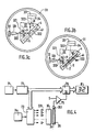
- Figure 1 is shown schematically a tank 1 containing a liquid 2.
- the invention relates to a device 3 for measuring the level of liquid 2 in the tank 1.
- the liquid 2 is fuel and the tank 1 is mounted on board a motor vehicle.
- the device 3 comprises a sealed housing 31, intended to support and protect its constituents.
- the housing 31 is made integral with the reservoir 1 by its upper part which adapts to an orifice provided for this purpose in the upper wall of the reservoir 1.
- the housing 31 extends over the entire height of the reservoir 1. Here it has the shape of a circular cylinder.
- an elongated transparent prism 32 Between the upper part of the housing 31 and its bottom are notably arranged, as appears in FIG. 2, an elongated transparent prism 32, a printed circuit board 33 supporting a plurality of light-emitting diodes 331, a polarizer 34 and a section 35 d 'a light guide.
- the prism 32 has a triangular base, and its three lateral faces here extend vertically over the entire height of the reservoir 1.
- the first lateral face 321 is called the entry face, because the light from the diodes 331 penetrates into the prism 32 by this entry face 321.
- the second lateral face 322 is called the reflection face because the light from the diodes 331 which has penetrated into the prism 32 through the entry face 321 is reflected on this reflection face 322, at least in part .
- the third lateral face 323 is called the output face, because the light from the diodes 331 which is reflected by the reflection face 322 comes out of the prism 32 through this outlet face 323.
- the base of the prism 32 is an isosceles triangle, the two equal sides of which correspond to the inlet 321 and outlet 323 faces, and the third side of which corresponds to the reflection face 322.
- the two angles equals of this isosceles triangle are notes i B.
- the reflection face 322 of the prism 32 is coated with a layer 4 of protective varnish, clearly visible in Figures 3 or its thickness has been considerably dilated, for the sake of clarity.
- the thickness of layer 4 is here substantially equal to 10 microns.
- the reflecting face 322 of the prism 32 is immersed over a height corresponding to that of the liquid 2 in the reservoir 1, a wall 5 is sealed on the face 322, leaving an elongated volume free 41 which communicates with the volume of the reservoir 1 through an orifice 311 made in the bottom of the housing 31.
- the level of the liquid 2 in the volume 41 which extends along the reflection face 322 is the same as that in the reservoir 1, the orifice 311 allowing the filtering of sudden variations in the level of the liquid 2 which result from the vibrations and accelerations of the vehicle.
- the diodes 331 are aligned here, and the plate 33 is arranged so that the light from the diodes 331 penetrates through the input face 321 under normal incidence, the diodes 331 being here regularly and vertically distributed along the input face 321.
- the diodes 331 are controlled by an electronic circuit 7.
- the polarizer 34 is disposed along the output face 323. Its direction of polarization is parallel to the plane of incidence of the light from each diode 331 on the reflection face 322, here a horizontal plane.
- the polarizer 34 therefore allows itself to be traversed only by the component of the light polarized rectilinearly in the direction parallel to the horizontal plane of incidence.
- the section 35 is also arranged along the outlet face 323, so that the polarizer 34 is located between the section 35 and the outlet face 323.
- the section 35 is here made of transparent material charged with a fluorescent substance. More particularly, and by way of example, the material in question here is an optically pure transparent polymer of the PMMA family colored by a fluorescent dye and marketed by the company BAYER under the registered trademark "Lisa".
- a photodetector 351 Opposite the upper straight section of the section 35 is a photodetector 351, here a photodiode, connected to the electronic circuit 7.
- the electronic circuit 7 is connected to a display device 8 to indicate the level measured.
- i B Arc tg (n V /not)
- FIG 3a there is illustrated the path of a light beam 332 from a diode 331 located at a height high enough for the portion of the reflection face 322 located at its level is not submerged.
- This light beam 332 crosses the input face 321 under normal incidence, and arrives on the reflection face 322 at an angle of incidence i B.
- the value i B defined by the relation (1) is none other than that of the Brewster incidence for the prism-varnish diopter of the reflection face 323, when the light comes from inside the prism 32, this which is the case for beam 332.
- the useful part of the beam 332 therefore undergoes a total reflection on the varnish-air diopter, and, following a path symmetrical to that which it had followed hitherto, successively crosses the reflection face 322, the exit face 323, the polarizer 34 and is collected by the section 35.
- the section 35 there is, in a known manner, a conversion of the light energy of the beam 332 into fluorescence light, this fluorescence light then being guided towards photodiode 351 with very good efficiency.
- the ratio defined by formula (5) takes the numerical value 5.10 ⁇ 7 for the example currently described.
- the electronic circuit 7 includes a clock 71 which delivers a clock signal to the counting input of a counter 72.
- the digital output of the counter 72 is connected on the one hand to the input of a flip-flop circuit 76 and d on the other hand to the control input of a multiplexer 73 provided moreover with a single input connected to a voltage source 74, and with a plurality of outputs each of which is connected to each of the diodes 331, respectively.
- the output of photodiode 351 is connected to an input of a comparator 75, the other input of which receives a threshold signal S.
- the output of comparator 75 is connected to the clock input of flip-flop circuit 76, the output is connected to the display device 8.
- the electronic circuit 7 operates as explained now.
- the digital output of the counter 72 increases by one at each clock stroke of the clock 71.
- each of the diodes 331 is successively connected to the source 74, designed to cause it to ignite.
- the diodes 331 are therefore lit sequentially one after the other.
- the intensity of the light collected by the section 35 is therefore representative of the light reflected by the portion of the reflection face 322 which is at the level of the lit diode.
- the comparator 75 permanently compares this intensity to the threshold S. Assuming the multiplexer 73 arranged so that the first lit diode is that disposed at the bottom of the tank, the second that disposed immediately above, and so on, comparator 75 generates a transition as soon as the output signal from the photodiode 351 crosses the threshold S, that is to say as soon as the lit diode is located just above the level of the liquid 2 in the reservoir 1.
- the output signal from the comparator 75 "freezes" the output value of the flip-flop circuit 76 to a value which copies its input value, and which indicates the rank of the diode 331 which is located just above the level of the liquid.
- the indication of the display device 8 is therefore representative of the level of the liquid.
- the electronic circuit 7 sequentially turns on each of the sources and determines the level of the liquid in response to the intensity of the light collected.
- the device is insensitive to aging or fouling of its constituents, since it is sufficient that the difference between two consecutive values of the collected light intensity is detected, the determination of the level proper then starting from the row of diode 331 which gave rise to this difference.
- FIG. 5 is shown a variant of the device of the invention.
- the housing 31 and the prism 32 are replaced by a housing 31 'and a 32 ′ prism, respectively.
- the housing 31 ′ and the prism 32 ′ form a single, sealed part produced during a single molding operation.
- the prism 32 ′ is an integral part of the housing 31 and is formed by an extra thickness, or protuberance, prismatic of the wall of the housing 31 ′, produced here in PPMA.
- a simpler and more compact structure is thus obtained, the cross section of which can have dimensions of the order of 20 mm.
- sealing problems are simplified.
- the reflection face 322 is located outside the housing 31 ′, and is naturally in contact with the liquid to be measured without it being necessary to provide a volume similar to the volume 41 of FIGS. 3.
- the wall 5 which spares this volume 41 has however been maintained, so that the variations in the level in the volume 41 are filtered with respect to those of the reservoir 1.
- the wall 5 need not be sealed in a leaktight manner, which is the case in the device of FIGS. 3.
- the protective layer of varnish 4 shown in this figure on a more realistic scale than in figures 3, without however being correct, since the layer 4 is here of a thickness of 10 microns, as has been reported.
- the electronic circuit 7 which has only been described by way of example can be improved to in particular perform filtering of the measurements.
- the sequential lighting of the diodes can be relatively fast, which makes it possible to obtain a relatively large flow of measurements, measurements which can be filtered electronically.
- the decrease in level of the liquid is generally relatively slow, it is also possible, once a first value of the level has been detected, to limit the sequential scanning of the diodes 331 to those which are in the vicinity of the detected level, of which the variations are then followed.
- the diodes 331 are distributed uniformly along the entry face of the prism in the case of a reservoir of regular shape, where the volume of the liquid is proportional to its level. In the case of an irregularly shaped reservoir, and where one is interested in the remaining volume of the liquid, the variations in volume as a function of the level can be compensated by a judicious distribution of the diodes. To increase the resolution of the device, it is necessary to increase the number of diodes, which can lead to having them staggered, or in any other way capable of solving the problems of congestion.
- the diode 331 located at the bottom of the tank can be used for an empty tank warning device.
- the polarizer 34 is not necessarily arranged between the outlet face 323 and the section 35. It suffices that it is disposed between the emitting diodes 331 and the section 35, and could therefore be placed between the diodes 331 and the face d 'entry 321.
- the device of the invention by lighting all the diodes 331 at the same time, or by providing a single source illuminating the whole of the input face 321, and by measuring the intensity of the collected light. .
Landscapes
- Physics & Mathematics (AREA)
- Electromagnetism (AREA)
- Thermal Sciences (AREA)
- Fluid Mechanics (AREA)
- General Physics & Mathematics (AREA)
- Measurement Of Levels Of Liquids Or Fluent Solid Materials (AREA)
Applications Claiming Priority (2)
| Application Number | Priority Date | Filing Date | Title |
|---|---|---|---|
| FR8915703 | 1989-11-29 | ||
| FR8915703A FR2655154B1 (de) | 1989-11-29 | 1989-11-29 |
Publications (3)
| Publication Number | Publication Date |
|---|---|
| EP0447728A2 true EP0447728A2 (de) | 1991-09-25 |
| EP0447728A3 EP0447728A3 (en) | 1991-11-21 |
| EP0447728B1 EP0447728B1 (de) | 1995-02-01 |
Family
ID=9387914
Family Applications (1)
| Application Number | Title | Priority Date | Filing Date |
|---|---|---|---|
| EP19900403355 Expired - Lifetime EP0447728B1 (de) | 1989-11-29 | 1990-11-27 | Optischer Prismenfüllstandsmesser im Flüssigkeitsbehälter |
Country Status (3)
| Country | Link |
|---|---|
| EP (1) | EP0447728B1 (de) |
| DE (1) | DE69016640D1 (de) |
| FR (1) | FR2655154B1 (de) |
Cited By (9)
| Publication number | Priority date | Publication date | Assignee | Title |
|---|---|---|---|---|
| EP0460432B1 (de) * | 1990-05-29 | 1995-11-02 | AC & R COMPONENTS, INC. | System zur Kontrolle des Oelniveaus |
| FR2791132A1 (fr) * | 1999-03-15 | 2000-09-22 | Clesse Ind | Dispositif indicateur de niveau dans un reservoir de gaz de petrole liquefie |
| FR2791131A1 (fr) * | 1999-03-15 | 2000-09-22 | Clesse Ind | Dispositif indicateur de niveau dans un reservoir de gaz de petrole liquefie |
| LU90533B1 (fr) * | 2000-03-01 | 2001-09-04 | Clesse Ind | Dispositid indicateur de niveau dans un r-servoir de gaz de p-trole liqu-fi- |
| EP1058099A3 (de) * | 1999-05-19 | 2001-11-07 | UMM Electronics, Inc. | Flüssigkeitsdetektor |
| US6658933B2 (en) | 2001-06-22 | 2003-12-09 | Clesse Industries | Fill-level indicator for a liquefied-petroleum-gas tank |
| RU2231028C2 (ru) * | 2002-03-06 | 2004-06-20 | Тараканов Валерий Александрович | Способ определения высоты уровня жидкости (варианты) |
| NL2010203C2 (en) * | 2013-01-30 | 2014-08-04 | Opw Fluid Transfer Group Europ B V | Optical liquid level detection sensor and liquid overfill prevention system comprising such sensor. |
| US11566931B2 (en) * | 2012-05-21 | 2023-01-31 | Bigfoot Biomedical, Inc. | Dose measurement system and method |
Families Citing this family (4)
| Publication number | Priority date | Publication date | Assignee | Title |
|---|---|---|---|---|
| FR2757271B1 (fr) * | 1996-12-13 | 1999-01-15 | Benichou Robert | Appareil de controle du niveau d'un fluide dans un reservoir |
| CN101782419B (zh) * | 2010-03-17 | 2011-06-22 | 哈尔滨工程大学 | 基于等腰直角三角棱镜的液位测量方法及测量装置 |
| GB2533374A (en) * | 2014-12-18 | 2016-06-22 | Airbus Operations Ltd | A gauge for indicating a height of a liquid |
| EP3452156B1 (de) * | 2016-05-03 | 2022-01-26 | Mallinckrodt Pharmaceuticals Ireland Limited | Vorrichtung zum erfassen des flüssigkeitsspiegels in einem transparenten oder teilweise transparenten behälter |
Family Cites Families (3)
| Publication number | Priority date | Publication date | Assignee | Title |
|---|---|---|---|---|
| FR2386818A1 (fr) * | 1977-04-06 | 1978-11-03 | Grumman Aerospace Corp | Dispositif electro-optique pour la mesure de la densite d'un fluide |
| EP0228217A1 (de) * | 1985-12-18 | 1987-07-08 | LUCAS INDUSTRIES public limited company | Flüssigkeitsstandanzeiger |
| IT1219123B (it) * | 1988-03-18 | 1990-05-03 | Veglia Borletti Srl | Metodo per il rilevamento del livello di un liquido in un serbatoio e sensore realizzante tale metodo |
-
1989
- 1989-11-29 FR FR8915703A patent/FR2655154B1/fr not_active Expired
-
1990
- 1990-11-27 DE DE69016640T patent/DE69016640D1/de not_active Expired - Lifetime
- 1990-11-27 EP EP19900403355 patent/EP0447728B1/de not_active Expired - Lifetime
Cited By (11)
| Publication number | Priority date | Publication date | Assignee | Title |
|---|---|---|---|---|
| EP0460432B1 (de) * | 1990-05-29 | 1995-11-02 | AC & R COMPONENTS, INC. | System zur Kontrolle des Oelniveaus |
| FR2791132A1 (fr) * | 1999-03-15 | 2000-09-22 | Clesse Ind | Dispositif indicateur de niveau dans un reservoir de gaz de petrole liquefie |
| FR2791131A1 (fr) * | 1999-03-15 | 2000-09-22 | Clesse Ind | Dispositif indicateur de niveau dans un reservoir de gaz de petrole liquefie |
| EP1058099A3 (de) * | 1999-05-19 | 2001-11-07 | UMM Electronics, Inc. | Flüssigkeitsdetektor |
| LU90533B1 (fr) * | 2000-03-01 | 2001-09-04 | Clesse Ind | Dispositid indicateur de niveau dans un r-servoir de gaz de p-trole liqu-fi- |
| US6658933B2 (en) | 2001-06-22 | 2003-12-09 | Clesse Industries | Fill-level indicator for a liquefied-petroleum-gas tank |
| RU2231028C2 (ru) * | 2002-03-06 | 2004-06-20 | Тараканов Валерий Александрович | Способ определения высоты уровня жидкости (варианты) |
| US11566931B2 (en) * | 2012-05-21 | 2023-01-31 | Bigfoot Biomedical, Inc. | Dose measurement system and method |
| NL2010203C2 (en) * | 2013-01-30 | 2014-08-04 | Opw Fluid Transfer Group Europ B V | Optical liquid level detection sensor and liquid overfill prevention system comprising such sensor. |
| WO2014120005A1 (en) * | 2013-01-30 | 2014-08-07 | Opw Fluid Transfer Group Europe B.V. | Optical liquid level detection sensor and liquid overfill prevention system comprising such sensor |
| US9869576B2 (en) | 2013-01-30 | 2018-01-16 | Opw Fluid Transfer Group Europe B.V. | Optical liquid level detection sensor and liquid overfill prevention system comprising such sensor |
Also Published As
| Publication number | Publication date |
|---|---|
| FR2655154A1 (de) | 1991-05-31 |
| FR2655154B1 (de) | 1992-02-28 |
| EP0447728B1 (de) | 1995-02-01 |
| DE69016640D1 (de) | 1995-03-16 |
| EP0447728A3 (en) | 1991-11-21 |
Similar Documents
| Publication | Publication Date | Title |
|---|---|---|
| EP0049220B1 (de) | Einrichtung mit doppeltem optischen Eintauchkörper zum Bestimmen des zu einer vorbestimmten Referenztemperatur zurückgeführten Beugungsindexes einer Flüssigkeit | |
| EP0447728B1 (de) | Optischer Prismenfüllstandsmesser im Flüssigkeitsbehälter | |
| FR2940448A1 (fr) | Guide d'onde perfectionne et spectrometre associe embarque dans un vehicule automobie | |
| FR2548355A1 (fr) | Systeme optique d'arpentage a laser | |
| EP0025586A1 (de) | Vorrichtung für optische Kupplung | |
| CN2551992Y (zh) | 一种盐水浓度测量装置 | |
| FR2602863A1 (fr) | Capteur de detection de taux air-carburant | |
| FR2581206A1 (fr) | Transducteur optique a fibre optique | |
| EP0453226A2 (de) | Faseroptischer Flüssigkeitsleckdetektor | |
| FR2524633A1 (fr) | Interferometre a ondes stationnaires pour la mesure des differences de trajets optiques | |
| WO2004051211A2 (fr) | Detecteur par voie optique de la presence de bulles de gaz dans un liquide | |
| FR2656688A1 (fr) | Dispositif de mesure du niveau d'un liquide dans un reservoir par determination optique de la position d'un flotteur. | |
| FR2653555A1 (fr) | Dispositif optique de mesure du niveau d'un liquide dans un reservoir, par collection et guidage de la lumiere d'une source. | |
| EP0299840B1 (de) | Korrelator mit optischer Faser | |
| EP4475102B1 (de) | Optische detektion der öffnung eines gehäuses | |
| EP0670487A1 (de) | Verfahren und Vorrichtung zur Bestimmung der Absorption einer elektromagnetischen Strahlung durch ein Gas | |
| FR2865802A1 (fr) | Dispositif de mesure du niveau d'un liquide | |
| EP0023902B1 (de) | Optische vorrichtung zur regelung oder steuerung von licht | |
| EP3973256B1 (de) | Faseroptischer akustischer sensor und zugehöriges messsystem, fahrzeug und messverfahren | |
| EP0448415B1 (de) | Abstandsdetektionsanordnung einer physikalischen Grösse durch Reflektion | |
| US20230064160A1 (en) | Prism for Measuring Liquid Concentration | |
| FR2538545A1 (fr) | Dispositif de mesure du niveau d'un liquide dans un reservoir | |
| EP0052551A2 (de) | Refraktometer mit Verwendung des Grenzwinkelverfahrens | |
| EP0499545B1 (de) | Empfänger zum paralellen Demultiplexen für ein optisches Sensornetzwerk mit Spektralmodulationskodierung | |
| FR2560679A1 (fr) | Jaugeur de reservoir de liquide notamment pour aeronef |
Legal Events
| Date | Code | Title | Description |
|---|---|---|---|
| PUAI | Public reference made under article 153(3) epc to a published international application that has entered the european phase |
Free format text: ORIGINAL CODE: 0009012 |
|
| AK | Designated contracting states |
Kind code of ref document: A2 Designated state(s): DE ES GB IT |
|
| PUAL | Search report despatched |
Free format text: ORIGINAL CODE: 0009013 |
|
| AK | Designated contracting states |
Kind code of ref document: A3 Designated state(s): DE ES GB IT |
|
| 17P | Request for examination filed |
Effective date: 19920520 |
|
| 17Q | First examination report despatched |
Effective date: 19940504 |
|
| GRAA | (expected) grant |
Free format text: ORIGINAL CODE: 0009210 |
|
| AK | Designated contracting states |
Kind code of ref document: B1 Designated state(s): DE ES GB IT |
|
| PG25 | Lapsed in a contracting state [announced via postgrant information from national office to epo] |
Ref country code: IT Free format text: LAPSE BECAUSE OF FAILURE TO SUBMIT A TRANSLATION OF THE DESCRIPTION OR TO PAY THE FEE WITHIN THE PRE;WARNING: LAPSES OF ITALIAN PATENTS WITH EFFECTIVE DATE BEFORE 2007 MAY HAVE OCCURRED AT ANY TIME BEFORE 2007. THE CORRECT EFFECTIVE DATE MAY BE DIFFERENT FROM THE ONE RECORDED.SCRIBED TIME-LIMIT Effective date: 19950201 Ref country code: GB Effective date: 19950201 Ref country code: ES Free format text: THE PATENT HAS BEEN ANNULLED BY A DECISION OF A NATIONAL AUTHORITY Effective date: 19950201 |
|
| REF | Corresponds to: |
Ref document number: 69016640 Country of ref document: DE Date of ref document: 19950316 |
|
| PG25 | Lapsed in a contracting state [announced via postgrant information from national office to epo] |
Ref country code: DE Effective date: 19950503 |
|
| GBV | Gb: ep patent (uk) treated as always having been void in accordance with gb section 77(7)/1977 [no translation filed] |
Effective date: 19950201 |
|
| PLBE | No opposition filed within time limit |
Free format text: ORIGINAL CODE: 0009261 |
|
| STAA | Information on the status of an ep patent application or granted ep patent |
Free format text: STATUS: NO OPPOSITION FILED WITHIN TIME LIMIT |
|
| 26N | No opposition filed |