EP0447700B1 - Optical fiber coupler - Google Patents
Optical fiber coupler Download PDFInfo
- Publication number
- EP0447700B1 EP0447700B1 EP90302943A EP90302943A EP0447700B1 EP 0447700 B1 EP0447700 B1 EP 0447700B1 EP 90302943 A EP90302943 A EP 90302943A EP 90302943 A EP90302943 A EP 90302943A EP 0447700 B1 EP0447700 B1 EP 0447700B1
- Authority
- EP
- European Patent Office
- Prior art keywords
- optical fiber
- fiber coupler
- diameter
- wavelength
- fused
- Prior art date
- Legal status (The legal status is an assumption and is not a legal conclusion. Google has not performed a legal analysis and makes no representation as to the accuracy of the status listed.)
- Expired - Lifetime
Links
Images

Classifications
-
- G—PHYSICS
- G02—OPTICS
- G02B—OPTICAL ELEMENTS, SYSTEMS OR APPARATUS
- G02B6/00—Light guides; Structural details of arrangements comprising light guides and other optical elements, e.g. couplings
- G02B6/24—Coupling light guides
- G02B6/26—Optical coupling means
- G02B6/28—Optical coupling means having data bus means, i.e. plural waveguides interconnected and providing an inherently bidirectional system by mixing and splitting signals
- G02B6/293—Optical coupling means having data bus means, i.e. plural waveguides interconnected and providing an inherently bidirectional system by mixing and splitting signals with wavelength selective means
- G02B6/29331—Optical coupling means having data bus means, i.e. plural waveguides interconnected and providing an inherently bidirectional system by mixing and splitting signals with wavelength selective means operating by evanescent wave coupling
- G02B6/29332—Wavelength selective couplers, i.e. based on evanescent coupling between light guides, e.g. fused fibre couplers with transverse coupling between fibres having different propagation constant wavelength dependency
-
- G—PHYSICS
- G02—OPTICS
- G02B—OPTICAL ELEMENTS, SYSTEMS OR APPARATUS
- G02B6/00—Light guides; Structural details of arrangements comprising light guides and other optical elements, e.g. couplings
- G02B6/24—Coupling light guides
- G02B6/26—Optical coupling means
- G02B6/28—Optical coupling means having data bus means, i.e. plural waveguides interconnected and providing an inherently bidirectional system by mixing and splitting signals
- G02B6/2804—Optical coupling means having data bus means, i.e. plural waveguides interconnected and providing an inherently bidirectional system by mixing and splitting signals forming multipart couplers without wavelength selective elements, e.g. "T" couplers, star couplers
- G02B6/2821—Optical coupling means having data bus means, i.e. plural waveguides interconnected and providing an inherently bidirectional system by mixing and splitting signals forming multipart couplers without wavelength selective elements, e.g. "T" couplers, star couplers using lateral coupling between contiguous fibres to split or combine optical signals
- G02B6/2835—Optical coupling means having data bus means, i.e. plural waveguides interconnected and providing an inherently bidirectional system by mixing and splitting signals forming multipart couplers without wavelength selective elements, e.g. "T" couplers, star couplers using lateral coupling between contiguous fibres to split or combine optical signals formed or shaped by thermal treatment, e.g. couplers
Definitions
- the present invention concerns optical fiber couplers employed in communication systems.
- the above described optical fiber coupling technique has the following shortcoming:
- quartz glass single mode optical fiber is used to form the optical fiber coupler, because the properties of the material are such that very little light energy is lost through the lateral surface of the fiber, the fused-elongated region must be quite long in order to sufficiently achieve optical coupling.
- the resulting diameters of the component optical fibers in the fused-elongated region end up being considerably reduced.
- quartz optical fibers having an outer diameter of 125 ⁇ m
- the fibers have a final outer diameter in the order of 20 ⁇ m. Because of this effect, even a relatively small curvature in the optical fiber results in light leaking through the side of the fiber to the exterior with loss in light energy. With a larger amount of bending in the optical fiber, the bending losses become significant.
- the present invention provides an optical fiber coupler formed by fusing a section of each of two or more component optical fibers, and then elongating the fused section thereby forming a fused-elongated region which constitutes the optical fiber coupler, in which at least one of the component fibers is a single mode optical fiber having a parameter range in which the mode field diameter increases monotonically with decrease in the diameter of the optical fiber core.
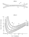
- Fig. 2 is a graph illustrating the relationship between core diameter and diameter of the mode field for a single mode optical fiber.
- Figs. 4 and 5 are graphs illustrating the relationship between wavelength and dispersion for the optical fibers.
- the optical fiber coupler 11 of the present embodiment as shown in Fig. 1 consists of a fused-elongated region 14 formed by thermally fusing and then drawing out a section of each of two component optical fibers 12 and 13, one of which is a conventional quartz single mode optical fiber 12 (hereafter referred to as conventional fiber), and one of which is a single mode optical fiber 13 characterized by having a parameter range in which the mode field diameter increases monotonically with decrease in the diameter of the optical fiber core.
- the fused-elongated region 14 thus manufactured had a minimum outer diameter of 45 ⁇ m, and a length of 7 mm.
- the measured value for loss from the thus produced optical fiber coupler 11 was 0.1 dB which is extremely low.
- optical fiber material for which the refractive index difference is high, and for which the core diameter is such that the structural parameters lie in the region to the left of the line 1B in Fig. 2.
- the so called wave guide dispersion is high.
- Figs. 4 and 5 examples of the wavelength dispersion characteristics can be seen for conventional optical fiber suitable for transmitting light signals at a wavelength of 1.3 ⁇ m of which the refractive index difference is high and of which the core diameter is small.
- the waveguide dispersion is low, and in the vicinity of 1.3 ⁇ m, the wavelength dispersion representing the sum of the wave guide dispersion and materials dispersion is zero.
- the mode propagation state also varies.
- the mode propagation velocity also varies.
- the propagation constant of the respective component optical fibers 12, 16 can be varied to match desired values.
- desired propagation constant for the two component fibers 12, 16 which are different and then thermally fusing together a portion of each component optical fiber 12, 16 and drawing out the fused portion as described above to form the fused-elongated region 17, the wavelength dependance characteristics of the resulting optical fiber coupler 15 can be controlled.
- an optical fiber coupler which is largely wavelength independent (or wide band-pass type optical fiber coupler) can be fabricated.
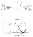
- the optical fiber coupler 19 of the present embodiment as shown in Fig. 6 consists of a fused-elongated region 20 formed by thermally fusing and then drawing out a section of each of two component optical fibers, both of which are the same as the dispersion shifted fiber 16 employed in the optical fiber coupler 15 described above for the second embodiment of the present invention.
- the fused-elongated region 20 thus manufactured had a minimum outer diameter of 55 ⁇ m, and a length of 10 mm.
Description
- The present invention concerns optical fiber couplers employed in communication systems.
- In one type of optical fiber coupler known in the art, two or more fibers are aligned side by side in a plane and thermally fused and elongated, thereby forming a fused-elongated region.
- In the fused-elongated region thus formed, the diameter of each component optical fiber is reduced, as is the diameter of the core of each fiber. To the extent that diameter of the cores of the optical fibers are reduced, a proportionately larger fraction of the light propagated therein leaks through the clad which surrounds the core of each fiber. Also, to the extent that the component optical fibers are drawn out and thereby elongated, the distance between the cores of adjacent optical fibers is reduced, and due to this fact, the coupling between the propagated modes of the individual fibers becomes extremely great. In this way, the light signal carried by one fiber branches and is thus caused to be multiplexed over two or more optical fibers.
- However, the above described optical fiber coupling technique has the following shortcoming:
When conventional quartz glass single mode optical fiber is used to form the optical fiber coupler, because the properties of the material are such that very little light energy is lost through the lateral surface of the fiber, the fused-elongated region must be quite long in order to sufficiently achieve optical coupling. Further, in order to form a fused-elongated region of sufficient length, the resulting diameters of the component optical fibers in the fused-elongated region end up being considerably reduced. For example, starting with quartz optical fibers having an outer diameter of 125 µm, it is possible that in the fused-elongated region of the resulting coupler, the fibers have a final outer diameter in the order of 20 µm. Because of this effect, even a relatively small curvature in the optical fiber results in light leaking through the side of the fiber to the exterior with loss in light energy. With a larger amount of bending in the optical fiber, the bending losses become significant. - In answer to the above described difficulties, it is an object of the present invention to provide an optical fiber coupler that can be fabricated with ease and from which losses are minimal.
- As the result of various experiments, it has been found that by employing a single mode optical fiber within a parameter range in which the mode field diameter increases monotonically with decrease in the diameter of the optical fiber core, that even when the amount of optical fiber elongation is limited, adequate optical coupling can be achieved.
- Accordingly, the present invention provides an optical fiber coupler formed by fusing a section of each of two or more component optical fibers, and then elongating the fused section thereby forming a fused-elongated region which constitutes the optical fiber coupler, in which at least one of the component fibers is a single mode optical fiber having a parameter range in which the mode field diameter increases monotonically with decrease in the diameter of the optical fiber core. By virtue of this feature, the amount of elongation or drawing of each component fiber which is carried out after fusing the fibers can be limited while still achieving adequate optical coupling.
- The invention is therefore to be distinguished from that described in US-A-4755037 which is generally concerned with the geometry of the intermediate tapering regions and the existance of a central fused region with parallel side walls.
- Fig. 1 is a sideview of the optical fiber coupler of a first embodiment of the present invention.
- Fig. 2 is a graph illustrating the relationship between core diameter and diameter of the mode field for a single mode optical fiber.
- Fig. 3 is a side view of the optical fiber coupler of a second embodiment of the present invention.
- Figs. 4 and 5 are graphs illustrating the relationship between wavelength and dispersion for the optical fibers.
- Fig. 6 is a sideview of the optical fiber coupler of a third embodiment of the present invention.
- Fig. 7 is a graph illustrating one example of the relationship between wavelength and coupling ratio for the optical fiber coupler shown in Fig. 6.
- In the following section, the first embodiment of the present invention will be described with reference to Figs. 1 and 2.
- The optical fiber coupler 11 of the present embodiment as shown in Fig. 1 consists of a fused-
elongated region 14 formed by thermally fusing and then drawing out a section of each of two componentoptical fibers optical fiber 13 characterized by having a parameter range in which the mode field diameter increases monotonically with decrease in the diameter of the optical fiber core. For the single modeoptical fiber 13, it is preferable to use quartz single mode optical fiber of which the extent of its mode (mode field diameter) rapidly increases with decrease in the diameter of its core, and hence, with drawing out of the fiber. - In Fig. 2, the relationship between core diameter and mode field diameter for conventional quartz single mode optical fiber suitable for transmitting optical signals at a wavelength of 1.3 µm is graphically illustrated. In the graph, a series of approximately parallel curves are shown, each of which represents a fiber having a different value for the refractive index difference between the clad and the core. As can be seen in the graph, a curve has a respective minimum value for the mode field diameter corresponding with a particular value for the diameter of the fiber core. The
line 1B in the drawing interconnects the minimum values of the respective curves. The above mentioned refractive index difference (RRID) is calculated by Equ. 1 below in which m₁ represents the refractive index for the core material and m₂ represents the refractive index for the cladding material.
In Fig. 2, the region 1A relates to a range for the structural parameters characteristic of the conventional quartz single mode optical fiber, the structural parameters being as follows: core diameter 9 - 10 µm, refractive index difference 0.28 - 0.35 %, external diameter of clad 125 µm. As shown in the graph, the region 1A corresponds to a relatively low mode field diameter, and thus indicates a parameter range not very suitable for the fully formed optical fiber coupler. Further, this region 1A is significantly to the right of the above mentionedline 1B which coincides with minimum values of mode field diameter for various examples of the optical fiber. Thus, if starting material corresponding with the region 1A were to be used for the single modeoptical fiber 13 used to form the optical fiber coupler of the present invention, a considerable amount of drawing of the fused fibers would be required to obtain a coupler in which the single modeoptical fiber 13 possesses a suitably large mode field diameter, which would accordingly result in an excessively long optical fiber coupler. Thus it can be seen that for the single modeoptical fiber 13, it is preferable to use quartz single mode optical fiber of which the structural parameters correspond with a point somewhere to the left of theline 1B in Fig. 2. - Because in the optical fiber coupler 11 of the present embodiment, one of the two fibers which are fused together to form the coupler is a single mode
optical fiber 13 characterized by having a parameter range in which the mode field diameter increases monotonically with decrease in the diameter of the optical fiber core, the amount of drawing out of the fused component fibers can be limited to a relatively small amount while still achieving adequate optical coupling. For this reason, it is possible to fabricate a small sized optical fiber coupler 11. - In the optical fiber coupler 11 of this first preferred embodiment as described, only one
conventional fiber 12 and one single modeoptical fiber 13 each were employed. However, it is also possible to incorporate a plurality of theconventional fibers 12 and/or a plurality of the single modeoptical fibers 13 in the manufacture of such an optical fiber coupler 11. The coupler may also be manufactured using only two or more of the single modeoptical fibers 13. - Using a quartz optical fiber suitable for transmitting light signals at a wavelength of 1.3 µm having a core diameter of 5 µm, an external clad diameter of 125 µm, and a refractive index difference of 0.3 % for the single mode
optical fiber 13, and a single mode quartz optical fiber having a core diameter of 9 µm, an external clad diameter of 125 µm, and a refractive index difference of 0.3 %, for theconventional fiber 12, a portion of each were aligned side by side and thermally fused. The fused portion was then draw out to produce an optical fiber coupler 11 of the same type as that of the first embodiment as shown in Fig. 1. The fused-elongated region 14 thus manufactured had a minimum outer diameter of 45 µm, and a length of 7 mm. The measured value for loss from the thus produced optical fiber coupler 11 was 0.1 dB which is extremely low. - In the following section, the second embodiment of the present invention will be described with reference to Fig. 3.
- The
optical fiber coupler 15 of the present embodiment as shown in Fig. 3 consists of a fused-elongated region 17 formed by thermally fusing and then drawing out a section of each of two componentoptical fibers conventional fiber 12, and one of which is a single modeoptical fiber 16 characterized by having negligible wavelength dispersion and being a dispersion shifted optical fiber at wavelengths of 1.4 µm and greater (hereafter referred to as dispersion shifted fiber 16). - For the above mentioned dispersion shifted
fiber 16, the bending loss characteristics are extremely good, and the refractive index difference (Δ %) is comparatively high. Additionally, the core diameter is such that the structural parameters lie in the region to the left of theline 1B in Fig. 2. - In general, it cannot be said that bending loss characteristics are always good with optical fiber having a comparatively low refractive index difference. In order to improve the bending loss characteristics, it is desirable to use optical fiber material for which the refractive index difference is high, and for which the core diameter is such that the structural parameters lie in the region to the left of the
line 1B in Fig. 2. With such optical fiber material, because change in the mode field diameter is sensitive to variation in the core diameter or regulated variation of the light frequency, the so called wave guide dispersion is high. - In Figs. 4 and 5, examples of the wavelength dispersion characteristics can be seen for conventional optical fiber suitable for transmitting light signals at a wavelength of 1.3 µm of which the refractive index difference is high and of which the core diameter is small. For the optical fiber material represented in Fig. 4, the waveguide dispersion is low, and in the vicinity of 1.3 µm, the wavelength dispersion representing the sum of the wave guide dispersion and materials dispersion is zero. Concerning the above mentioned waveguide dispersion, because the measured value varies with respect to the wavelength of the propagated light, the mode propagation state also varies. Similarly, concerning the above mentioned materials dispersion, because the refractive index difference for the optical fiber material varies with the wavelength of the propagated light, the mode propagation velocity also varies.
- In the case of Fig. 5, the optical fiber material again has a refractive index difference which is high and a small core diameter. However, for the material represented by Fig. 5, the waveguide dispersion is high. Due to the high wave guide dispersion, the wavelength dispersion is shifted towards longer wavelengths. The above mentioned dispersion shifted
fiber 16 is an example of an optical fiber material for which the wave guide dispersion has been intentionally shifted to a higher value in this way. For this kind of dispersion shiftedfiber 16, the wavelength at which the wavelength dispersion value becomes zero is shifted to a wavelength longer than 1.3 µm, and is generally in the range of 1.4 - 1.6 µm. When the wavelength at which the wavelength dispersion value becomes zero is shorter than 1.4 µm, an optical fiber having sufficiently stable characteristics in response to bending is not obtainable. Thus when used to form an optical fiber coupler, there is increased chance for optical losses in the portions of the optical fiber leading up to the optical fiber coupler. - With the
optical fiber coupler 15 of the present preferred embodiment, by choosing optical fiber materials having selected values for the refractive index difference for the two component optical fibers,conventional fiber 12, and dispersion shiftedfiber 16, the propagation constant of the respective componentoptical fibers component fibers optical fiber region 17, the wavelength dependance characteristics of the resultingoptical fiber coupler 15 can be controlled. By this means, an optical fiber coupler which is largely wavelength independent (or wide band-pass type optical fiber coupler) can be fabricated. - Further, by using a dispersion shifted
fiber 16 having superior stability characteristics in response to fiber bending, the resultingoptical fiber coupler 15 includeslead fibers 18 leading up to the fused-elongatedregion 17 for which the stability characteristics in response to fiber bending are supported. - Using a quartz optical fiber suitable for transmitting light signals at a wavelength of 1.3 µm having a core diameter of 9 µm, an external clad diameter of 125 µm, and a refractive index difference of 0.3 % for the
conventional fiber 12, and an optical fiber having a core diameter of 4 µm, an external clad diameter of 125 µm, a refractive index difference of 0.7 %, and a zero wavelength dispersion value at 1.55 µm for the dispersion shiftedfiber 16, a portion of each were aligned side by side and thermally fused. The fused portion was then drawn out to produce anoptical fiber coupler 15 of the same type as that of the second embodiment as shown in Fig. 3. The fused-elongatedregion 17 thus manufactured had a minimum outer diameter of 55 µm, and a length of 6 mm. The measured value for loss from the thus producedoptical fiber coupler 15 was 0.05 dB which is extremely low. Further, when thelead fiber 18 of theoptical fiber coupler 15 manufactured as described above was bent in the form of a curve having a bending curvature of 10 mm, the additional optical loss was only 0.1 dB. Using a prior art coupler suitable for light signals at a wavelength of 1.3 µm, bending a lead under the same conditions demonstrated an additional loss of 0.5 dB. - Examining the wavelength dependance characteristics of the
optical fiber coupler 15 manufactured as described above, it was found that theoptical fiber coupler 15 was minimally wavelength dependant and could be used over a wide range of wavelengths as a wavelength independent optical fiber coupler (wide band-width type optical fiber coupler). - In the following section, the third embodiment of the present invention will be described with reference to Fig. 6.
- The
optical fiber coupler 19 of the present embodiment as shown in Fig. 6 consists of a fused-elongatedregion 20 formed by thermally fusing and then drawing out a section of each of two component optical fibers, both of which are the same as the dispersion shiftedfiber 16 employed in theoptical fiber coupler 15 described above for the second embodiment of the present invention. - With the
optical fiber coupler 19 of the present embodiment, by appropriately controlling the elongation ratio of the fused-elongatedregion 20, it is possible to fabricate a selective wavelength splitter type optical fiber coupler in which at certain wavelengths, essentially no light is transmitted and at certain other wavelengths, essentially 100 % transmission is achieved. - By constructing the
optical fiber coupler 19 using two of the dispersion shiftedfibers 16, of which only one is employed in theoptical fiber coupler 15 described above for the second embodiment, anoptical fiber coupler 19 with even greater stability characteristics in response to bending can be fabricated. - Using two dispersion shifted
optical fibers 16, each having a zero wavelength dispersion value at 1.55 µm, a portion of each were aligned side by side and thermally fused. The fused portion was then draw out to produce anoptical fiber coupler 19 of the same type as that of the third preferred embodiment as shown in Fig. 6. The fused-elongatedregion 20 thus manufactured had a minimum outer diameter of 55 µm, and a length of 10 mm. - Measuring the optical coupling wavelength characteristics of the
optical fiber coupler 19 of the present experimental example, it was found that theoptical fiber coupler 19 could be used as a selective wavelength splitter type optical fiber coupler. That is to say, of the fourports port 2C and one emitted fromport 2D. - The various examples of the present invention presented in the above preferred embodiments are merely examples and are in no way to be construed as limiting the present invention. It is possible, for example, to employ three or more optical fibers in the optical fiber coupler of the present invention with acceptable results. It should be understood that the optical fiber coupler of the present invention includes all forms encompassed by the appended claims.
Claims (3)
- An optical fiber coupler formed by fusing a section of each of two or more component optical fibers, and then elongating the fused section to form a fused-elongated region, in which at least one of said component optical fibers is a single mode optical fiber having a parameter range such that as the diameter of the core of said optical fiber is reduced, the diameter of the mode field for said optical fiber increases monotonically.
- An optical fiber coupler in accordance with Claim 1, in which said single mode optical fiber is a dispersion shifted single mode fiber for which the wavelength value at which wavelength dispersion becomes zero is 1.4µm or greater.
- An optical fiber coupler in accordance with claim 1, in which said two or more component optical fibers are dispersion shifted single mode fibers for which the wavelength value at which wavelength dispersion become zero is 1.4µm or greater.
Priority Applications (2)
| Application Number | Priority Date | Filing Date | Title |
|---|---|---|---|
| DE1990614602 DE69014602T2 (en) | 1990-03-19 | 1990-03-19 | Fiber optic directional coupler. |
| EP94107139A EP0610973B1 (en) | 1990-03-07 | 1990-03-19 | Optical fiber coupler |
Applications Claiming Priority (1)
| Application Number | Priority Date | Filing Date | Title |
|---|---|---|---|
| US07/490,026 US5066087A (en) | 1990-03-07 | 1990-03-07 | Optical fiber coupler |
Related Child Applications (2)
| Application Number | Title | Priority Date | Filing Date |
|---|---|---|---|
| EP94107139.1 Division-Into | 1990-03-19 | ||
| EP94107139A Division EP0610973B1 (en) | 1990-03-07 | 1990-03-19 | Optical fiber coupler |
Publications (2)
| Publication Number | Publication Date |
|---|---|
| EP0447700A1 EP0447700A1 (en) | 1991-09-25 |
| EP0447700B1 true EP0447700B1 (en) | 1994-11-30 |
Family
ID=23946309
Family Applications (2)
| Application Number | Title | Priority Date | Filing Date |
|---|---|---|---|
| EP90302943A Expired - Lifetime EP0447700B1 (en) | 1990-03-07 | 1990-03-19 | Optical fiber coupler |
| EP94107139A Expired - Lifetime EP0610973B1 (en) | 1990-03-07 | 1990-03-19 | Optical fiber coupler |
Family Applications After (1)
| Application Number | Title | Priority Date | Filing Date |
|---|---|---|---|
| EP94107139A Expired - Lifetime EP0610973B1 (en) | 1990-03-07 | 1990-03-19 | Optical fiber coupler |
Country Status (2)
| Country | Link |
|---|---|
| US (1) | US5066087A (en) |
| EP (2) | EP0447700B1 (en) |
Families Citing this family (14)
| Publication number | Priority date | Publication date | Assignee | Title |
|---|---|---|---|---|
| US5179603A (en) * | 1991-03-18 | 1993-01-12 | Corning Incorporated | Optical fiber amplifier and coupler |
| JPH04322207A (en) * | 1991-04-23 | 1992-11-12 | Japan Aviation Electron Ind Ltd | Optical fiber coupler and its manufacture |
| JPH05127040A (en) * | 1991-11-06 | 1993-05-25 | Shin Etsu Chem Co Ltd | Holder of fiber type optical coupler |
| US5410626A (en) * | 1992-06-25 | 1995-04-25 | Kyocera Corporation | Optical coupler having a tapered fused region |
| JP3049697B2 (en) * | 1992-07-29 | 2000-06-05 | 住友電気工業株式会社 | Mode field diameter conversion fiber |
| US5355426A (en) * | 1992-09-02 | 1994-10-11 | Gould Electronics Inc. | Broadband MXN optical fiber couplers and method of making |
| US5303373A (en) * | 1992-10-16 | 1994-04-12 | Schott Fiber Optics, Inc. | Anamorphic fused fiber optic bundle |
| JPH06250042A (en) * | 1993-03-01 | 1994-09-09 | Shin Etsu Chem Co Ltd | Wide wavelength region optical fiber type coupler and its production |
| JPH07318746A (en) * | 1994-05-20 | 1995-12-08 | Seiko Giken:Kk | Optical demultiplexer/multiplexer for optical fibers having reflection coating of high reflectivity in coupling part |
| GB0219141D0 (en) * | 2002-08-16 | 2002-09-25 | Alcatel Optronics Uk Ltd | Optical branching component with low polarisation sensitivity |
| US6826341B2 (en) * | 2002-11-04 | 2004-11-30 | Fitel Usa Corp. | Systems and methods for reducing splice loss in optical fibers |
| GB2395796A (en) | 2002-11-27 | 2004-06-02 | Alcatel Optronics Uk Ltd | Optical waveguide branching component with MMI couplers |
| US7272280B2 (en) * | 2004-12-16 | 2007-09-18 | Honeywell International Inc. | Optical coupler for measuring wavelength |
| WO2009035104A1 (en) * | 2007-09-14 | 2009-03-19 | Tatsuta Electric Wire & Cable Co., Ltd. | Optical fiber for optical fiber coupler and optical fiber coupler |
Family Cites Families (7)
| Publication number | Priority date | Publication date | Assignee | Title |
|---|---|---|---|---|
| US4490163A (en) * | 1982-03-22 | 1984-12-25 | U.S. Philips Corporation | Method of manufacturing a fiber-optical coupling element |
| GB8519183D0 (en) * | 1985-07-30 | 1985-09-04 | British Telecomm | Optical fused couplers |
| DE8601064U1 (en) | 1986-01-17 | 1987-05-21 | Robert Bosch Gmbh, 7000 Stuttgart, De | |
| GB2190762B (en) * | 1986-05-23 | 1989-12-13 | Stc Plc | Directional coupler |
| US4755037A (en) * | 1987-04-13 | 1988-07-05 | Mcdonnell Douglas Corporation | Fiber optic coupler |
| GB2207254B (en) * | 1987-07-11 | 1991-03-13 | Stc Plc | Glass clad optical fibre directional couplers. |
| JP2635720B2 (en) * | 1988-10-18 | 1997-07-30 | 株式会社フジクラ | Optical fiber coupler |
-
1990
- 1990-03-07 US US07/490,026 patent/US5066087A/en not_active Expired - Lifetime
- 1990-03-19 EP EP90302943A patent/EP0447700B1/en not_active Expired - Lifetime
- 1990-03-19 EP EP94107139A patent/EP0610973B1/en not_active Expired - Lifetime
Also Published As
| Publication number | Publication date |
|---|---|
| EP0610973A2 (en) | 1994-08-17 |
| US5066087A (en) | 1991-11-19 |
| EP0610973A3 (en) | 1995-01-18 |
| EP0610973B1 (en) | 1999-01-13 |
| EP0447700A1 (en) | 1991-09-25 |
Similar Documents
| Publication | Publication Date | Title |
|---|---|---|
| EP0447700B1 (en) | Optical fiber coupler | |
| EP0783117B1 (en) | Optical fibers for optical attenuation | |
| AU721745B2 (en) | Optical couplers with multilayer fibers | |
| US4798436A (en) | Optical fused couplers | |
| US5675688A (en) | Dispersion-shifted monomode optical fiber | |
| AU677819B2 (en) | Narrow band Mach-Zehnder filter | |
| EP0692722A2 (en) | Optical attenuator | |
| WO1998029768A9 (en) | Optical couplers with multilayer fibers | |
| AU707442B2 (en) | Bragg grating filter | |
| CA2024225C (en) | Optical fiber coupler | |
| US4976512A (en) | Narrowband fiberoptic spectral filter formed from fibers having a refractive index with a W profile and a step profile | |
| US6088494A (en) | Aperiodic Mach-Zehnder optical filters | |
| EP0021712A1 (en) | Dielectric waveguides and method of propagating polarized electromagnetic waves and communication apparatus and system using such waveguides and method | |
| JP3784593B2 (en) | Single / multimode optical fiber coupler and method of manufacturing the same | |
| KR100585016B1 (en) | Single mode optical fiber structure having high-order mode extinction filtering function | |
| US5559913A (en) | Broadband integrated optical proximity coupler | |
| EP0308244A2 (en) | Optical filter coupler | |
| JP2635720B2 (en) | Optical fiber coupler | |
| US4904040A (en) | Optical waveguide coupler for monitoring | |
| US4618258A (en) | Method for measuring loop coupling efficiency | |
| JP2848832B2 (en) | Broadband optical fiber coupler | |
| US5946432A (en) | Periodic mach-zehnder optical filters | |
| JPH0750722Y2 (en) | Optical fixed attenuator | |
| JPH09311221A (en) | Light attenuatable optical fiber | |
| Nolan | Multiply tapered fiber devices |
Legal Events
| Date | Code | Title | Description |
|---|---|---|---|
| PUAI | Public reference made under article 153(3) epc to a published international application that has entered the european phase |
Free format text: ORIGINAL CODE: 0009012 |
|
| 17P | Request for examination filed |
Effective date: 19901127 |
|
| AK | Designated contracting states |
Kind code of ref document: A1 Designated state(s): DE FR GB |
|
| 17Q | First examination report despatched |
Effective date: 19930511 |
|
| GRAA | (expected) grant |
Free format text: ORIGINAL CODE: 0009210 |
|
| AK | Designated contracting states |
Kind code of ref document: B1 Designated state(s): DE FR GB |
|
| XX | Miscellaneous (additional remarks) |
Free format text: TEILANMELDUNG 94107139.1 EINGEREICHT AM 14/10/91. |
|
| REF | Corresponds to: |
Ref document number: 69014602 Country of ref document: DE Date of ref document: 19950112 |
|
| ET | Fr: translation filed | ||
| PLBE | No opposition filed within time limit |
Free format text: ORIGINAL CODE: 0009261 |
|
| STAA | Information on the status of an ep patent application or granted ep patent |
Free format text: STATUS: NO OPPOSITION FILED WITHIN TIME LIMIT |
|
| 26N | No opposition filed | ||
| REG | Reference to a national code |
Ref country code: GB Ref legal event code: IF02 |
|
| PGFP | Annual fee paid to national office [announced via postgrant information from national office to epo] |
Ref country code: DE Payment date: 20080313 Year of fee payment: 19 |
|
| PGFP | Annual fee paid to national office [announced via postgrant information from national office to epo] |
Ref country code: GB Payment date: 20090318 Year of fee payment: 20 |
|
| PGFP | Annual fee paid to national office [announced via postgrant information from national office to epo] |
Ref country code: FR Payment date: 20090316 Year of fee payment: 20 |
|
| PG25 | Lapsed in a contracting state [announced via postgrant information from national office to epo] |
Ref country code: DE Free format text: LAPSE BECAUSE OF NON-PAYMENT OF DUE FEES Effective date: 20091001 |
|
| REG | Reference to a national code |
Ref country code: GB Ref legal event code: PE20 Expiry date: 20100318 |
|
| PG25 | Lapsed in a contracting state [announced via postgrant information from national office to epo] |
Ref country code: GB Free format text: LAPSE BECAUSE OF EXPIRATION OF PROTECTION Effective date: 20100318 |