EP0447641B1 - Speed detecting device for non-driving wheels of vehicles - Google Patents
Speed detecting device for non-driving wheels of vehicles Download PDFInfo
- Publication number
- EP0447641B1 EP0447641B1 EP90124090A EP90124090A EP0447641B1 EP 0447641 B1 EP0447641 B1 EP 0447641B1 EP 90124090 A EP90124090 A EP 90124090A EP 90124090 A EP90124090 A EP 90124090A EP 0447641 B1 EP0447641 B1 EP 0447641B1
- Authority
- EP
- European Patent Office
- Prior art keywords
- axle
- cap
- blocking means
- sensor
- nut
- Prior art date
- Legal status (The legal status is an assumption and is not a legal conclusion. Google has not performed a legal analysis and makes no representation as to the accuracy of the status listed.)
- Expired - Lifetime
Links
- 230000000903 blocking effect Effects 0.000 claims description 11
- 210000002105 tongue Anatomy 0.000 claims description 4
- 230000002093 peripheral effect Effects 0.000 claims 3
- 238000005096 rolling process Methods 0.000 claims 2
- 230000015556 catabolic process Effects 0.000 description 2
- 239000000463 material Substances 0.000 description 2
- 238000012423 maintenance Methods 0.000 description 1
- 239000002184 metal Substances 0.000 description 1
Images

Classifications
-
- G—PHYSICS
- G01—MEASURING; TESTING
- G01P—MEASURING LINEAR OR ANGULAR SPEED, ACCELERATION, DECELERATION, OR SHOCK; INDICATING PRESENCE, ABSENCE, OR DIRECTION, OF MOVEMENT
- G01P3/00—Measuring linear or angular speed; Measuring differences of linear or angular speeds
- G01P3/42—Devices characterised by the use of electric or magnetic means
- G01P3/44—Devices characterised by the use of electric or magnetic means for measuring angular speed
- G01P3/443—Devices characterised by the use of electric or magnetic means for measuring angular speed mounted in bearings
-
- F—MECHANICAL ENGINEERING; LIGHTING; HEATING; WEAPONS; BLASTING
- F16—ENGINEERING ELEMENTS AND UNITS; GENERAL MEASURES FOR PRODUCING AND MAINTAINING EFFECTIVE FUNCTIONING OF MACHINES OR INSTALLATIONS; THERMAL INSULATION IN GENERAL
- F16C—SHAFTS; FLEXIBLE SHAFTS; ELEMENTS OR CRANKSHAFT MECHANISMS; ROTARY BODIES OTHER THAN GEARING ELEMENTS; BEARINGS
- F16C33/00—Parts of bearings; Special methods for making bearings or parts thereof
- F16C33/72—Sealings
- F16C33/723—Shaft end sealing means, e.g. cup-shaped caps or covers
-
- F—MECHANICAL ENGINEERING; LIGHTING; HEATING; WEAPONS; BLASTING
- F16—ENGINEERING ELEMENTS AND UNITS; GENERAL MEASURES FOR PRODUCING AND MAINTAINING EFFECTIVE FUNCTIONING OF MACHINES OR INSTALLATIONS; THERMAL INSULATION IN GENERAL
- F16C—SHAFTS; FLEXIBLE SHAFTS; ELEMENTS OR CRANKSHAFT MECHANISMS; ROTARY BODIES OTHER THAN GEARING ELEMENTS; BEARINGS
- F16C41/00—Other accessories, e.g. devices integrated in the bearing not relating to the bearing function as such
- F16C41/007—Encoders, e.g. parts with a plurality of alternating magnetic poles
-
- B—PERFORMING OPERATIONS; TRANSPORTING
- B60—VEHICLES IN GENERAL
- B60G—VEHICLE SUSPENSION ARRANGEMENTS
- B60G2204/00—Indexing codes related to suspensions per se or to auxiliary parts
- B60G2204/10—Mounting of suspension elements
- B60G2204/11—Mounting of sensors thereon
- B60G2204/115—Wheel hub bearing sensors
-
- F—MECHANICAL ENGINEERING; LIGHTING; HEATING; WEAPONS; BLASTING
- F16—ENGINEERING ELEMENTS AND UNITS; GENERAL MEASURES FOR PRODUCING AND MAINTAINING EFFECTIVE FUNCTIONING OF MACHINES OR INSTALLATIONS; THERMAL INSULATION IN GENERAL
- F16C—SHAFTS; FLEXIBLE SHAFTS; ELEMENTS OR CRANKSHAFT MECHANISMS; ROTARY BODIES OTHER THAN GEARING ELEMENTS; BEARINGS
- F16C19/00—Bearings with rolling contact, for exclusively rotary movement
- F16C19/02—Bearings with rolling contact, for exclusively rotary movement with bearing balls essentially of the same size in one or more circular rows
- F16C19/14—Bearings with rolling contact, for exclusively rotary movement with bearing balls essentially of the same size in one or more circular rows for both radial and axial load
- F16C19/18—Bearings with rolling contact, for exclusively rotary movement with bearing balls essentially of the same size in one or more circular rows for both radial and axial load with two or more rows of balls
- F16C19/181—Bearings with rolling contact, for exclusively rotary movement with bearing balls essentially of the same size in one or more circular rows for both radial and axial load with two or more rows of balls with angular contact
- F16C19/183—Bearings with rolling contact, for exclusively rotary movement with bearing balls essentially of the same size in one or more circular rows for both radial and axial load with two or more rows of balls with angular contact with two rows at opposite angles
- F16C19/184—Bearings with rolling contact, for exclusively rotary movement with bearing balls essentially of the same size in one or more circular rows for both radial and axial load with two or more rows of balls with angular contact with two rows at opposite angles in O-arrangement
- F16C19/185—Bearings with rolling contact, for exclusively rotary movement with bearing balls essentially of the same size in one or more circular rows for both radial and axial load with two or more rows of balls with angular contact with two rows at opposite angles in O-arrangement with two raceways provided integrally on a part other than a race ring, e.g. a shaft or housing
-
- F—MECHANICAL ENGINEERING; LIGHTING; HEATING; WEAPONS; BLASTING
- F16—ENGINEERING ELEMENTS AND UNITS; GENERAL MEASURES FOR PRODUCING AND MAINTAINING EFFECTIVE FUNCTIONING OF MACHINES OR INSTALLATIONS; THERMAL INSULATION IN GENERAL
- F16C—SHAFTS; FLEXIBLE SHAFTS; ELEMENTS OR CRANKSHAFT MECHANISMS; ROTARY BODIES OTHER THAN GEARING ELEMENTS; BEARINGS
- F16C2326/00—Articles relating to transporting
- F16C2326/01—Parts of vehicles in general
- F16C2326/02—Wheel hubs or castors
Definitions
- This invention is referred to a speed detecting device for non-driving wheels of vehicles.
- the common widespread speed detecting systems for vehicle wheels consist of a sensor and a phonic wheel, and applied on the bearing of the wheel-hub, they should have the following characteristics:
- a speed gauging device mounted on a non-driving wheel is known from DE-U-8816381.
- This system provides a sensor which is either force-fitted in a trough hole in the axle or is driven onto a threaded nut thet keeps the inner race of the bearing in position. In this second case, the sensor is steadily fitted on said nut by means of a metal cup.
- EP-A-0317423 discloses a speed gauging sensor which is directly deep-drawn onto the axle of a non-driving wheel without any additional fixing member.
- a purpose of the present invention is to provide a device having all the above mentioned charateristics and in particular those ones, previously described, that the prior art is short of.
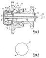
- figures 1 and 2 are axial cross sections of a wheel hub having the device according to this invention
- figures 3 and 4 are drafts showing details of figs. 1 and 2.
- a wheel hub is provided with an axle 10 that is slipped into an axle holder 11 and on which the inner races 12 of a bearing 13 are fixed.
- the outer race of the bearing is formed by wheel-holder body 14.
- the axle 10 has an end 15 with a restricted cross section on which a washer 16 is slipped; this is meant to compact the inner races 12 of the bearing 13 against the axle-holder 11.
- a nut 17 is screwed on the threaded end 15 so as to block the above described unit.
- the nut 17 is a traditional one, with a final lenght that, after the screwing, is pressed down into a milled seat obtained in the end 15 of the pin 10.
- This operation prevents the nut 17 from unscrewing off the axle 10 while it is working.
- the speed detecting device consists of a stem 18 made of sufficiently rigid material and which is slipped in a through hole of the axle 10. This stem leads the electronics towards the inside; these are to be connected with the computer by means of a connector 19 which is fitted on the outside of the axle 10.
- the stem 18 has a cap 21, the front shape of which is schematically shown in fig. 3. This shape allows it to be mounted on nut 17 so that it can cover with its hollow parts 20 the above mentioned pressed down part of the nut. In this way it is kept centered position with respect to the nut itself and it can be easily oriented in the right way during the assembly.
- Tongues 22 are obtained inside cap 21 for axially and circumferentially blocking stem 18; said tongues slip into the corresponding slots 23 of the end 15 of the axle 10.
- the cap 21 of the stem 18 holds the sensor 24 which is electrically connected to the computer through the stem 18 and is facing the phonic wheel 25.
- This can be mounted directly on the inside of body 14 or as an appendix of the lid 26 that covers the unit for protecting it from crashes and external contaminating elements.
- the nut 17 has no portions that crush, so the circumferential blockage of cap 21 is realized by simply forming a waved circumferential surface 27 (fig. 4) on the washer 16 on which the cap 21 spring locks.
- the cap 21 will be provided with a circumferential undercut obtained on one of its cylindrical appendixes 28.
- the tongues 29 on the end of the cylindrical appendix 28 realize the blocking in the axial direction of the cap 21, that is they prevent it from being accidentally untightened.
- cap 21 If necessary, in case of maintenance or breakdown, it is quite easy to release the cap 21 from its axial and circumferential restraints as the cap 21 and the stem 18, although being rigid, are elasticly yielding, for example in plastic material.
Landscapes
- Engineering & Computer Science (AREA)
- General Engineering & Computer Science (AREA)
- Mechanical Engineering (AREA)
- Physics & Mathematics (AREA)
- General Physics & Mathematics (AREA)
- Rolling Contact Bearings (AREA)
Description
- This invention is referred to a speed detecting device for non-driving wheels of vehicles.
- The common widespread speed detecting systems for vehicle wheels consist of a sensor and a phonic wheel, and applied on the bearing of the wheel-hub, they should have the following characteristics:
- be easily mounted on the bearing;
- keep a correct and constant positioning in time, in radial, axial and circumferential directions;
- have the possibility of being easily and quickly disassembled in the case of a breakdown of the same devices or of the members that are connected wiht them;
- be easily and reliably connected with the vehicle's computer;
- the sensor must be protected from external contaminating elements;
- the electronics must be sheltered from crashes and as far as possible from all heat sources.
- Tha actual solutions have only a few of the foregoing characteristics, combined in between them in various ways.
- However, the first two above mentioned characteristics, that is to be easily mounted and correctly positioned have not been obtained satisfactorily.
- It is obvious that these are basic characteristics, as the first one affects the assembling time and expense, while the second one is determinant as to reliability and for correct operation of the device.
- A speed gauging device mounted on a non-driving wheel is known from DE-U-8816381. This system provides a sensor which is either force-fitted in a trough hole in the axle or is driven onto a threaded nut thet keeps the inner race of the bearing in position. In this second case, the sensor is steadily fitted on said nut by means of a metal cup.
- EP-A-0317423 discloses a speed gauging sensor which is directly deep-drawn onto the axle of a non-driving wheel without any additional fixing member.
- Both of the cited references fail to disclose a speed detecting device that can be releasably secured to the bearing both axially and circumferentially in order to attain the aforementioned characteristics.
- A purpose of the present invention is to provide a device having all the above mentioned charateristics and in particular those ones, previously described, that the prior art is short of.
- For these and other purposes, that will appear more clearly further on, it is an object of this invention to provide a speed detecting device according to claim 1 or 2.
- The device according to the invention is now going to be described in two alternative embodiments, referring to the enclosed drawings, in which: figures 1 and 2 are axial cross sections of a wheel hub
having the device according to this invention; figures 3 and 4 are drafts showing details of figs. 1 and 2. - Traditionally, a wheel hub is provided with an
axle 10 that is slipped into anaxle holder 11 and on which theinner races 12 of abearing 13 are fixed. The outer race of the bearing is formed by wheel-holder body 14. - The
axle 10 has anend 15 with a restricted cross section on which awasher 16 is slipped; this is meant to compact theinner races 12 of the bearing 13 against the axle-holder 11. - A
nut 17 is screwed on the threadedend 15 so as to block the above described unit. - Referring now expressely to the embodiment of figs. 1 and 3, the
nut 17 is a traditional one, with a final lenght that, after the screwing, is pressed down into a milled seat obtained in theend 15 of thepin 10. - This operation, that is traditionally used, prevents the
nut 17 from unscrewing off theaxle 10 while it is working. - According to this invention, the speed detecting device consists of a
stem 18 made of sufficiently rigid material and which is slipped in a through hole of theaxle 10. This stem leads the electronics towards the inside; these are to be connected with the computer by means of aconnector 19 which is fitted on the outside of theaxle 10. - The
stem 18 has acap 21, the front shape of which is schematically shown in fig. 3. This shape allows it to be mounted onnut 17 so that it can cover with itshollow parts 20 the above mentioned pressed down part of the nut. In this way it is kept centered position with respect to the nut itself and it can be easily oriented in the right way during the assembly. -
Tongues 22 are obtained insidecap 21 for axially and circumferentially blockingstem 18; said tongues slip into thecorresponding slots 23 of theend 15 of theaxle 10. - The
cap 21 of thestem 18 holds thesensor 24 which is electrically connected to the computer through thestem 18 and is facing thephonic wheel 25. This can be mounted directly on the inside ofbody 14 or as an appendix of thelid 26 that covers the unit for protecting it from crashes and external contaminating elements. - In the embodiment of figs. 2 and 4 the
nut 17 has no portions that crush, so the circumferential blockage ofcap 21 is realized by simply forming a waved circumferential surface 27 (fig. 4) on thewasher 16 on which thecap 21 spring locks. For such purpose, thecap 21 will be provided with a circumferential undercut obtained on one of itscylindrical appendixes 28. Thetongues 29 on the end of thecylindrical appendix 28 realize the blocking in the axial direction of thecap 21, that is they prevent it from being accidentally untightened. - It is obvious that this realization is also equivalent in the frequent case in which the
nut 17 and thewasher 16 are integral. - Both of the above-described embodiments allow to mount the speed detecting device extremely simply and quickly, and realize a precise centering and positioning, both circumferentially and axially, as it is in the purposes of this invention.
- If necessary, in case of maintenance or breakdown, it is quite easy to release the
cap 21 from its axial and circumferential restraints as thecap 21 and thestem 18, although being rigid, are elasticly yielding, for example in plastic material.
Claims (5)
- A speed detecting device for non-driving wheels of vehicles consisting of a sensor (24) and of a phonic wheel (25) mounted respectively on the axle (10) and on a flanged body (14) carrying the wheel; the balls of a rolling bearing being interposed between the axle (10) and the body (14) for realizing the reciprocal rotation of said elements; the sensor (24) being mounted on the cap (21) of a stem (18) which is slipped in a through hole of the axle for being electrically connected to the vehicle's computer; the balls of the bearing (13) being mounted on inner races (12) fitted on the axle and axially held by blocking means (16,17), said blocking means (17) being screwed onto the outer end (15) of the axle (10) facing the cap (21) of the stem (18); characterised in that the cap (21) has a peripheral wave-like surface that copies corresponding side waves of said blocking means (16,17) for simplifying the orientation of the sensor (24) when the unit gets assembled; furthermore, the cap (21) having ulterior appendixes (29) that engage the axle (10) in its blocking means (16,17) so as to guarantee the axial and circumferential centering of the cap itself.
- A speed detecting device for non-driving wheels of vehicles consisting of a sensor (24) and of a phonic wheel (25) mounted respectively on the axle (10) and on a flanged body (14) carrying the wheel; the balls of a rolling bearing being interposed between the axle (10) and the body (14) for realizing the reciprocal rotation of said elements; the sensor (24) being mounted on the cap (21) of a stem (18) which is slipped in a through hole of the axle for being electrically connected to the vehicle's computer; the balls of the bearing (13) being mounted on inner races (12) fitted on the axle and axially held by blocking means (16,17), said blocking means (17) being screwed onto the outer end (15) of the axle (10) facing the cap (21) of the stem (18); characterised in that the cap (21) has a peripheral surface with hollow parts (20) copying the corresponding shape of said blocking means (17) for simplifying the orientation of the sensor (24) when the unit gets assembled; the cap (21) having further tongues (22) that extend from its inside and are rounded towards the axle (10) so as to engage corresponding slots (23) of the axle itself and guarantee the axial and circumferential centering of the cap itself.
- A device according to claim 2 in which the blocking means consist of a washer (16) slipped on the end (15) of the axle (10), pressed against the inner races (12) of the bearing (13) by means of a nut (17) that is screwed on the threaded end (15) of axle (10); the nut (17) having peripheral side surfaces suitable to be pressed down on corresponding axially disposed seats of the end (15) of the axle (10); the cap (21) having a substantially circular shape and being provided with two diametrally opposed hollow parts (20) copying said side parts of the nut (17) being pressed down on the end (15).
- A device according to claim 1 characterized in that the blocking means consist of a washer (16) slipped on the end (15) of the axle (10), and pressed against the inner races (12) of the bearing (13) by means of a nut (17) that is screwed on the threaded end (15) of the axle; and in that the washer (16) has a substantially circular waved periphery (27) that is made to fit inside a corresponding undercut obtained in a cylindrical appendix (28) of the cap (21); the circular extremity of cap (21) contacting axially said periphery (27) of the washer (16).
- A device according to claims 1 and 4 characterized in that the nut (17) and the washer (16) are realized as a whole is one piece.
Applications Claiming Priority (2)
| Application Number | Priority Date | Filing Date | Title |
|---|---|---|---|
| IT67071A IT1239872B (en) | 1990-01-30 | 1990-01-30 | SPEED DETECTION DEVICE FOR DIVEICLE NON-DRIVE WHEELS. |
| IT6707190 | 1990-01-30 |
Publications (2)
| Publication Number | Publication Date |
|---|---|
| EP0447641A1 EP0447641A1 (en) | 1991-09-25 |
| EP0447641B1 true EP0447641B1 (en) | 1994-07-13 |
Family
ID=11299353
Family Applications (1)
| Application Number | Title | Priority Date | Filing Date |
|---|---|---|---|
| EP90124090A Expired - Lifetime EP0447641B1 (en) | 1990-01-30 | 1990-12-13 | Speed detecting device for non-driving wheels of vehicles |
Country Status (3)
| Country | Link |
|---|---|
| EP (1) | EP0447641B1 (en) |
| DE (1) | DE69010665T2 (en) |
| IT (1) | IT1239872B (en) |
Families Citing this family (5)
| Publication number | Priority date | Publication date | Assignee | Title |
|---|---|---|---|---|
| IT1256785B (en) * | 1992-01-28 | 1995-12-15 | Skf Ind Spa | SEALING COMPLEX WITH A SENSOR DEVICE ON BOARD, FOR A ROLLING BEARING. |
| DE4412307A1 (en) * | 1994-04-09 | 1995-10-19 | Teves Metallwaren Alfred | Vehicle wheel with revolution rate measurement device |
| DE19501268A1 (en) * | 1995-01-18 | 1996-07-25 | Teves Metallwaren Alfred | Device for measuring rotary movements |
| ES2190189T3 (en) | 1999-11-23 | 2003-07-16 | Arol Spa | DEVICE AND PROCEDURE TO VERIFY THE SEALING OF A THREADED PLUG IN A CONTAINER. |
| EP2682621B1 (en) * | 2012-07-05 | 2015-02-25 | Aktiebolaget SKF | Instrumented bearing |
Family Cites Families (3)
| Publication number | Priority date | Publication date | Assignee | Title |
|---|---|---|---|---|
| FR2623136B1 (en) * | 1987-11-16 | 1990-03-09 | Skf France | ASSEMBLY OF A NON-DRIVING WHEEL HUB OF A VEHICLE EQUIPPED WITH A PULSE DEVICE AND SENSOR FOR MEASURING THE ROTATION SPEED OF THE WHEEL |
| JP2633274B2 (en) * | 1987-12-28 | 1997-07-23 | 光洋精工株式会社 | Bearing unit for automobile wheel |
| DE8816381U1 (en) * | 1988-04-23 | 1989-06-08 | FAG Kugelfischer Georg Schäfer AG, 97421 Schweinfurt | Rolling bearing unit, especially for wheels of motor vehicles with speed measuring device |
-
1990
- 1990-01-30 IT IT67071A patent/IT1239872B/en active IP Right Grant
- 1990-12-13 DE DE69010665T patent/DE69010665T2/en not_active Expired - Fee Related
- 1990-12-13 EP EP90124090A patent/EP0447641B1/en not_active Expired - Lifetime
Also Published As
| Publication number | Publication date |
|---|---|
| EP0447641A1 (en) | 1991-09-25 |
| IT9067071A1 (en) | 1991-07-30 |
| DE69010665D1 (en) | 1994-08-18 |
| DE69010665T2 (en) | 1994-12-08 |
| IT1239872B (en) | 1993-11-15 |
| IT9067071A0 (en) | 1990-01-30 |
Similar Documents
| Publication | Publication Date | Title |
|---|---|---|
| US5011303A (en) | Integrated bearing provided with a pulser and with a sensor for equipping a motor vehicle wheel hub | |
| US4969694A (en) | Wheel hub mounting with a pulse transmitter | |
| EP0767385B1 (en) | A bearing unit with a quick mounting rotational speed detector | |
| US5727886A (en) | Bearing device for axle | |
| EP1426257B1 (en) | Protective cap for wheel support bearing assembly | |
| US5097702A (en) | Automobile wheel hub | |
| US5002404A (en) | Radial rolling bearings | |
| US6924638B2 (en) | Arrangement for mounting rotation speed sensor to wheel bearing assembly | |
| CA1114436A (en) | Wheel mounting and tapered roller bearing therefor | |
| US5010290A (en) | Easily installed wheel bearing sensor package | |
| US5090236A (en) | Phonic element for speed sensing bearing assembly | |
| EP0937984B1 (en) | Roller contact bearing with a sealing device and a device for measuring rotation speed | |
| US4614869A (en) | Apparatus for detecting angle and angular velocity of rotation member and method of assembling it | |
| US5067350A (en) | Sensor to determine rotational parameters | |
| EP0447641A1 (en) | Speed detecting device for non-driving wheels of vehicles | |
| EP1602844B1 (en) | Rolling bearing unit | |
| EP0457007A1 (en) | Bearing apparatus for a driven shaft of an automobile, having a rotational speed detector | |
| EP1886147B1 (en) | A device for assembling and disassembling a sensor in a bearing unit | |
| JP3988576B2 (en) | Rolling bearing device | |
| US5062821A (en) | Arrangement of a protective cover on the socket of a transmission joint | |
| KR950014942B1 (en) | Device for measuring rotational parameters of the axis of rotation | |
| JPH0213769Y2 (en) | ||
| GB2151748A (en) | Wheel retaining device | |
| JP3985617B2 (en) | Rolling bearing device | |
| JP2005207571A (en) | Bearing lock structure |
Legal Events
| Date | Code | Title | Description |
|---|---|---|---|
| PUAI | Public reference made under article 153(3) epc to a published international application that has entered the european phase |
Free format text: ORIGINAL CODE: 0009012 |
|
| AK | Designated contracting states |
Kind code of ref document: A1 Designated state(s): DE FR GB SE |
|
| 17P | Request for examination filed |
Effective date: 19911219 |
|
| 17Q | First examination report despatched |
Effective date: 19921202 |
|
| GRAA | (expected) grant |
Free format text: ORIGINAL CODE: 0009210 |
|
| AK | Designated contracting states |
Kind code of ref document: B1 Designated state(s): DE FR GB SE |
|
| REF | Corresponds to: |
Ref document number: 69010665 Country of ref document: DE Date of ref document: 19940818 |
|
| ET | Fr: translation filed | ||
| EAL | Se: european patent in force in sweden |
Ref document number: 90124090.3 |
|
| PLBE | No opposition filed within time limit |
Free format text: ORIGINAL CODE: 0009261 |
|
| STAA | Information on the status of an ep patent application or granted ep patent |
Free format text: STATUS: NO OPPOSITION FILED WITHIN TIME LIMIT |
|
| 26N | No opposition filed | ||
| PGFP | Annual fee paid to national office [announced via postgrant information from national office to epo] |
Ref country code: FR Payment date: 19971119 Year of fee payment: 8 |
|
| PGFP | Annual fee paid to national office [announced via postgrant information from national office to epo] |
Ref country code: SE Payment date: 19971120 Year of fee payment: 8 |
|
| PGFP | Annual fee paid to national office [announced via postgrant information from national office to epo] |
Ref country code: DE Payment date: 19971125 Year of fee payment: 8 |
|
| PGFP | Annual fee paid to national office [announced via postgrant information from national office to epo] |
Ref country code: GB Payment date: 19971126 Year of fee payment: 8 |
|
| PG25 | Lapsed in a contracting state [announced via postgrant information from national office to epo] |
Ref country code: GB Free format text: LAPSE BECAUSE OF NON-PAYMENT OF DUE FEES Effective date: 19981213 |
|
| PG25 | Lapsed in a contracting state [announced via postgrant information from national office to epo] |
Ref country code: SE Free format text: LAPSE BECAUSE OF NON-PAYMENT OF DUE FEES Effective date: 19981214 |
|
| GBPC | Gb: european patent ceased through non-payment of renewal fee |
Effective date: 19981213 |
|
| PG25 | Lapsed in a contracting state [announced via postgrant information from national office to epo] |
Ref country code: FR Free format text: LAPSE BECAUSE OF NON-PAYMENT OF DUE FEES Effective date: 19990831 |
|
| REG | Reference to a national code |
Ref country code: FR Ref legal event code: ST |
|
| PG25 | Lapsed in a contracting state [announced via postgrant information from national office to epo] |
Ref country code: DE Free format text: LAPSE BECAUSE OF NON-PAYMENT OF DUE FEES Effective date: 19991001 |