EP0447617A2 - Optical magnetic recording and reproducing system - Google Patents
Optical magnetic recording and reproducing system Download PDFInfo
- Publication number
- EP0447617A2 EP0447617A2 EP90121215A EP90121215A EP0447617A2 EP 0447617 A2 EP0447617 A2 EP 0447617A2 EP 90121215 A EP90121215 A EP 90121215A EP 90121215 A EP90121215 A EP 90121215A EP 0447617 A2 EP0447617 A2 EP 0447617A2
- Authority
- EP
- European Patent Office
- Prior art keywords
- magnetic
- optical
- recording
- head
- disk
- Prior art date
- Legal status (The legal status is an assumption and is not a legal conclusion. Google has not performed a legal analysis and makes no representation as to the accuracy of the status listed.)
- Granted
Links
Images


Classifications
-
- G—PHYSICS
- G11—INFORMATION STORAGE
- G11B—INFORMATION STORAGE BASED ON RELATIVE MOVEMENT BETWEEN RECORD CARRIER AND TRANSDUCER
- G11B11/00—Recording on or reproducing from the same record carrier wherein for these two operations the methods are covered by different main groups of groups G11B3/00 - G11B7/00 or by different subgroups of group G11B9/00; Record carriers therefor
- G11B11/10—Recording on or reproducing from the same record carrier wherein for these two operations the methods are covered by different main groups of groups G11B3/00 - G11B7/00 or by different subgroups of group G11B9/00; Record carriers therefor using recording by magnetic means or other means for magnetisation or demagnetisation of a record carrier, e.g. light induced spin magnetisation; Demagnetisation by thermal or stress means in the presence or not of an orienting magnetic field
- G11B11/105—Recording on or reproducing from the same record carrier wherein for these two operations the methods are covered by different main groups of groups G11B3/00 - G11B7/00 or by different subgroups of group G11B9/00; Record carriers therefor using recording by magnetic means or other means for magnetisation or demagnetisation of a record carrier, e.g. light induced spin magnetisation; Demagnetisation by thermal or stress means in the presence or not of an orienting magnetic field using a beam of light or a magnetic field for recording by change of magnetisation and a beam of light for reproducing, i.e. magneto-optical, e.g. light-induced thermomagnetic recording, spin magnetisation recording, Kerr or Faraday effect reproducing
- G11B11/10532—Heads
- G11B11/10534—Heads for recording by magnetising, demagnetising or transfer of magnetisation, by radiation, e.g. for thermomagnetic recording
-
- G—PHYSICS
- G11—INFORMATION STORAGE
- G11B—INFORMATION STORAGE BASED ON RELATIVE MOVEMENT BETWEEN RECORD CARRIER AND TRANSDUCER
- G11B11/00—Recording on or reproducing from the same record carrier wherein for these two operations the methods are covered by different main groups of groups G11B3/00 - G11B7/00 or by different subgroups of group G11B9/00; Record carriers therefor
- G11B11/10—Recording on or reproducing from the same record carrier wherein for these two operations the methods are covered by different main groups of groups G11B3/00 - G11B7/00 or by different subgroups of group G11B9/00; Record carriers therefor using recording by magnetic means or other means for magnetisation or demagnetisation of a record carrier, e.g. light induced spin magnetisation; Demagnetisation by thermal or stress means in the presence or not of an orienting magnetic field
- G11B11/105—Recording on or reproducing from the same record carrier wherein for these two operations the methods are covered by different main groups of groups G11B3/00 - G11B7/00 or by different subgroups of group G11B9/00; Record carriers therefor using recording by magnetic means or other means for magnetisation or demagnetisation of a record carrier, e.g. light induced spin magnetisation; Demagnetisation by thermal or stress means in the presence or not of an orienting magnetic field using a beam of light or a magnetic field for recording by change of magnetisation and a beam of light for reproducing, i.e. magneto-optical, e.g. light-induced thermomagnetic recording, spin magnetisation recording, Kerr or Faraday effect reproducing
- G11B11/10502—Recording on or reproducing from the same record carrier wherein for these two operations the methods are covered by different main groups of groups G11B3/00 - G11B7/00 or by different subgroups of group G11B9/00; Record carriers therefor using recording by magnetic means or other means for magnetisation or demagnetisation of a record carrier, e.g. light induced spin magnetisation; Demagnetisation by thermal or stress means in the presence or not of an orienting magnetic field using a beam of light or a magnetic field for recording by change of magnetisation and a beam of light for reproducing, i.e. magneto-optical, e.g. light-induced thermomagnetic recording, spin magnetisation recording, Kerr or Faraday effect reproducing characterised by the transducing operation to be executed
- G11B11/10504—Recording
- G11B11/10508—Recording by modulating only the magnetic field at the transducer
-
- G—PHYSICS
- G11—INFORMATION STORAGE
- G11B—INFORMATION STORAGE BASED ON RELATIVE MOVEMENT BETWEEN RECORD CARRIER AND TRANSDUCER
- G11B11/00—Recording on or reproducing from the same record carrier wherein for these two operations the methods are covered by different main groups of groups G11B3/00 - G11B7/00 or by different subgroups of group G11B9/00; Record carriers therefor
- G11B11/10—Recording on or reproducing from the same record carrier wherein for these two operations the methods are covered by different main groups of groups G11B3/00 - G11B7/00 or by different subgroups of group G11B9/00; Record carriers therefor using recording by magnetic means or other means for magnetisation or demagnetisation of a record carrier, e.g. light induced spin magnetisation; Demagnetisation by thermal or stress means in the presence or not of an orienting magnetic field
- G11B11/105—Recording on or reproducing from the same record carrier wherein for these two operations the methods are covered by different main groups of groups G11B3/00 - G11B7/00 or by different subgroups of group G11B9/00; Record carriers therefor using recording by magnetic means or other means for magnetisation or demagnetisation of a record carrier, e.g. light induced spin magnetisation; Demagnetisation by thermal or stress means in the presence or not of an orienting magnetic field using a beam of light or a magnetic field for recording by change of magnetisation and a beam of light for reproducing, i.e. magneto-optical, e.g. light-induced thermomagnetic recording, spin magnetisation recording, Kerr or Faraday effect reproducing
- G11B11/10502—Recording on or reproducing from the same record carrier wherein for these two operations the methods are covered by different main groups of groups G11B3/00 - G11B7/00 or by different subgroups of group G11B9/00; Record carriers therefor using recording by magnetic means or other means for magnetisation or demagnetisation of a record carrier, e.g. light induced spin magnetisation; Demagnetisation by thermal or stress means in the presence or not of an orienting magnetic field using a beam of light or a magnetic field for recording by change of magnetisation and a beam of light for reproducing, i.e. magneto-optical, e.g. light-induced thermomagnetic recording, spin magnetisation recording, Kerr or Faraday effect reproducing characterised by the transducing operation to be executed
- G11B11/10515—Reproducing
Definitions
- the present invention relates to an optical magnetic recording and reproducing system capable of recording information on a magneto-optical disk at high density.
- a laser beam is focused on the magneto-optical disk to elevate the temperature of a point to be recorded.
- the disk is magnetized, thereby rendering the direction of the magnetic moment in a magnetic domainof the disk upward or downward.
- the information is represented by one or zero digital signals.
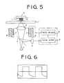
- Fig. 5 shows an example of a conventional optical magnetic recording and reproducing system employing the magnetic field modulation system.
- a laser beam from a laser device L is focused on a recording surface of the disk 1 through an objective 2.
- the beam reflected from the disk 1 is supplied to a focus error detector 4 through a beam splitter 3.
- the focus error detector 4 detects the focus error in accordance with the reflected beam, and applies a focus error signal to a focus servo 5.
- the focus servo 5 in turn applies a focus servo signal corresponding to the focus error signal to a driver 6.
- the driver 6 applies an exciting current in response to the servo signal to an actuator coil 7.
- the actuator coil 7 accordingly generates a magnetic field.
- the actuator coil 7 and hence the objective 2 are moved along the optical axis of the objective 2 due to a magnetic force of an actuator magnet 8.
- a lighter laser beam correctly focused through the focus servo system is emitted.
- the beam is reflected on the disk 1, and the direction of the polarization plane of the reflected beam is different in dependency on the direction of the magnetic domain, so that whether the reflected beam is one or zero can be determined.
- the information is reproduced as shown by a waveform shown in Fig. 6.
- Fig. 7 shows another conventional optical magnetic recording and reproducing system provided with a movable magnetic head 9.
- the magnetic head 9 is provided with an actuator coil 13 which generates a magnetic field in accordance with a servo signal from a magentic head driver 12, and an actuator magnet 14.
- the recording and reproducing system is constructed to move the magnetic head 9 to maintain the distance between the disk 1 and the magnetic head 9 constant in spite of the vibration or warp of the disk 1.
- the intensity of the magnetic field caused by the magnetic head 9 is kept constant, thereby reproducing information as shown by a waveform in Fig. 8.
- the magnitude of the distortion in the system having the fixed magnetic head is larger than that having the movable magnetic head. This is caused by the fact that in the system with the fixed head, the distance between the disk 1 and the magnetic head 9 fluctuates when the disk 1 vibrates, so that the magnetic field for recording the information also fluctuates. Consequently, when the magnetic field for recording the information is distorted, the information can not be accurately recorded or reproduced, thereby decreasing the reliability of the system.
- the object of the present invention is to provide an optical magnetic recording and reproducing system wherein information may be reliably recorded and reproduced.
- an optical magnetic recording and reproducing system having a magnetic head for generating a magnetic field on a magneto-optical disk, an optical head provided for irradiating a laser beam, a magnetic device for axially moving the optical head for focusing the laser beam on the magneto-optical disk, and a control unit for controlling the magnetic device for the focusing.
- Magnetic means is provided for producing a cancelling magnetic force so as to cancel a component included in a leakage magnetic force which affects recording of information.
- the magnetic means is a magnet attached to the magnetic head.
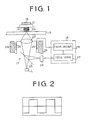
- an optical magnetic recording and reproducing system of the present invention comprises a fixed magnetic head 16 which generates a magnetic field on a magneto-optical disk 15 in response to an electric signal applied thereto, an optical head 17 for irradiating a laser beam and detecting the reflection thereof, and a control unit 18 for controlling a focus servo system of the optical head 17.
- the magnetic head 16 has a core 20 wound with an excitation coil 19 to which is applied a signal current.
- a resultant magnetic field which is harmful to the recording of information on the disk 15 is formed by a leakage of magnetic force from the optical head 17.
- the resultant magnetic field has a vertical component relative to a recording surface of the disk 15. Since the direction of the vertical component is specified, a bias magnet 21 is mounted on the magnetic head 16 so as to cancel the vertical component.
- the bias magnet 21 is disposed so as to orient the line of magnetic force thereof to oppose the vertical componet.
- the intensity of the magnetic field of the magnet 21 is set to coincide with the intensity of the vertical component.
- the optical head 17 comprises an objective 22 for forcusing the laser beam emitted from a semiconductor laser, a beam splitter 23 for changing the direction of the beam reflected on the disk 15, and a focus error detector 24.
- the focus error detector 24 is applied with the reflected beam through the beam splitter 23 and detects a focus error using astigmatism and produces an error signal which is fed to the control unit 18.
- the optical head 17 is further provided with an actuating coil 25 integral with the objective 22 and an actuator magnet 26.
- an exciting current from the control unit 18 is applied, the actuator coil 25 is excited, thereby generating a magnetic field.
- a magentic field of the actuator magnet 26 has a direction opposite to that generated by the actuator coil 25.
- the lens 22 is moved toward or away from the disk 15.
- the control unit 18 has a focus servo 27 which produces a focus servo signal in response to the error signal from the forcus error detector 24.
- the focus servo signal is fed to a focus driver 28 which in turn feeds the exciting current corresponding to the detected focus error to the actuator coil 25.
- optical magnetic recording and reproducing system The operation of the optical magnetic recording and reproducing system is described hereinafter.
- the laser beam is focused on a recording surface of the disk 15 through the objective 22.
- the beam reflected from the disk 15 is supplied to the focus error detector 24 through the beam splitter 23.
- the focus error detector 24 detects the focus error using astigmatism in accordance with the reflected beam applied thereto, and applies the focus error signal to the focus servo 27 of the control unit 18.
- the focus servo 27 in turn applies the focus servo signal corresponding to the focus error signal to the driver 28.
- the driver 28 applies the exciting current to the actuator coil 25 in response to the servo signal.
- the actuator coil 25 accordingly generates the magnetic field in dependency on the exciting current.
- the coil 25 and hence the objective 22 are moved along the optical axis of the objective 22 due to the repulsion force of the magnetic field generated by the coil 25 against the magnetic field of the actuator magnet 26.
- the objective 22 is ordinarily positioned so that the focus is deflected from the desired position.
- the level of the focus servo signal becomes higher so that the exciting current applied to the coil 25 is increased.
- the repulsion force between the actuator magnet 26 and the actuator coil 25 is increased so that the objective 22 moves toward the disk 15.
- the exciting current is reduced thereafter, the repulsion force of the magnet 26 decreases, thereby moving the objective 22 away from the disk 15.
- the temperature of the recording point thereon rises.
- the signal current is applied to the excitation coil 19 of the magnetic head 17, rendering the direction of the magnetic moment in a magnetic domain on a ferromagnetic material formed on the recording surface of the disk 15 upward or downward.
- information represented by one or zero digital signals is stored.
- the magnetic field which is hazardous to the recording of the information is caused by the leakage of the magnetic force from the actuator coil 25 and the actuator 26.
- the component of the magnetic field which is vertical to the recording surface of the disk 15 is cancelled by the bias magnet 21.
- the line of the magnetic force of the actuator coil 25 and the actuator magnet 26 is directed in a certain direction in relation to the recording surface.
- the line of magnetic force of the bias magnet 21 has a direction which is opposite to that of the vertical component, thereby cancelling it.
- a lighter beam is emitted.
- the beam reflected on the surface of the disk has a different polarization plane in dependency on the direction of the magnetic domain.
- the reflected beam can be determined whether the information is one or zero.
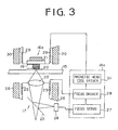
- the information can be accurately reproduced without any distortion as shown by a reproduction waveform shown in Fig. 2.
- the information can be rewritten on the disk 15 in the same manner as described hereinbefore.
- the second embodiment of the present invention shown in Fig. 3 is provided with a movable magnetic head 16a.
- the same numerals as those in Fig. 1 designate the same parts in Fig. 3 as Fig. 1 so that the description thereof are omitted.
- the magnetic head 16a is further provided with an actuator coil 29 and an actuator magnet 30.
- a control unit 18a has a magnetic head driver 31 which feeds an exciting current to the actuator coil 29 in response to the servo signal, in addition to the focus servo 27 and the driver 28 for actuating the actuator coil 25.
- the system of the second embodiment is constructed to maintain the distance between the disk 15 and the magnetic head 16a constant in spite of the vibration or warp of the disk 15.
- the magnetic field caused by the magnetic head 16a acting on the disk 15 is kept constant so that the recording and reproduction of information becomes more accurate compared to the system of the first embodiment.
- Fig. 4 shows the third embodiment of the present invention.
- the recording and reproducing system has a magnetic head 16b having the core 20 wound with the excitation coil 19.
- An offset signal supplying section 16d and a magnetic head driver 16c are provided in the system to cancel the vertical component of the resultant magnetic field which is caused by the leakage of the magnetic force.
- the offset signal supplying section 16d applies an offset signal, which is a direct current signal, to the excitation coil 19 through the driver 16c.
- the phase of the offset signal is set to oppose the vertical component of the resultant magnetic force.
- the level of the offset signal is determined to generate a magnetic field having the same intensity as the vertical component.
- the offset signal is applied to the excitation coil 19 when the electric signal is applied thereto.
- the bias magnet provided in the previous embodiments can be obviated, so that a compact system can be obtained.
- the magnetic head 16b of the third embodiment of the present invention is a fixed magnetic head
- the embodiment may be modified so as to be applied to a system with a movable magnetic head.
- the present invention provides an optical magnetic recording and reproducing system where the information is accurately recorded and reproduced so that the reliability of the system is ensured.
Abstract
Description
- The present invention relates to an optical magnetic recording and reproducing system capable of recording information on a magneto-optical disk at high density.
- In order to record information in the optical magnetic memory system, a laser beam is focused on the magneto-optical disk to elevate the temperature of a point to be recorded. On the other hand, the disk is magnetized, thereby rendering the direction of the magnetic moment in a magnetic domainof the disk upward or downward. Thus, the information is represented by one or zero digital signals.
- Fig. 5 shows an example of a conventional optical magnetic recording and reproducing system employing the magnetic field modulation system. In order to record information on a magneto-
optical disk 1, a laser beam from a laser device L is focused on a recording surface of thedisk 1 through anobjective 2. The beam reflected from thedisk 1 is supplied to afocus error detector 4 through abeam splitter 3. Thefocus error detector 4 detects the focus error in accordance with the reflected beam, and applies a focus error signal to afocus servo 5. Thefocus servo 5 in turn applies a focus servo signal corresponding to the focus error signal to adriver 6. Thedriver 6 applies an exciting current in response to the servo signal to anactuator coil 7. Theactuator coil 7 accordingly generates a magnetic field. Theactuator coil 7 and hence theobjective 2 are moved along the optical axis of theobjective 2 due to a magnetic force of anactuator magnet 8. - When the laser beam is thus correctly focused on the recording surface of the
disk 1, the temperature of the recording point thereon rises. At the same time, a signal current is applied to an excitation coil 11 which is wound around acore 12 mounted on a fixedmagnetic head 9, rendering the direction of the magnetic moment in a magnetic domain on a ferro magnetic material formed on the recording surface of the disk upward or downward. Thus, information represented by one or zero digital signals is stored. - When reproducing the recorded information, a lighter laser beam correctly focused through the focus servo system is emitted. The beam is reflected on the
disk 1, and the direction of the polarization plane of the reflected beam is different in dependency on the direction of the magnetic domain, so that whether the reflected beam is one or zero can be determined. Hence, the information is reproduced as shown by a waveform shown in Fig. 6. - Fig. 7 shows another conventional optical magnetic recording and reproducing system provided with a movable
magnetic head 9. Themagnetic head 9 is provided with anactuator coil 13 which generates a magnetic field in accordance with a servo signal from amagentic head driver 12, and anactuator magnet 14. - The recording and reproducing system is constructed to move the
magnetic head 9 to maintain the distance between thedisk 1 and themagnetic head 9 constant in spite of the vibration or warp of thedisk 1. Thus, the intensity of the magnetic field caused by themagnetic head 9 is kept constant, thereby reproducing information as shown by a waveform in Fig. 8. - However, in the above described magnetic field modulation method, a resultant magnetic field is generated due to a leak of magnetic force from the
actuator coils actuator magnets - Comparing the Figs. 6 and 8, the magnitude of the distortion in the system having the fixed magnetic head is larger than that having the movable magnetic head. This is caused by the fact that in the system with the fixed head, the distance between the
disk 1 and themagnetic head 9 fluctuates when thedisk 1 vibrates, so that the magnetic field for recording the information also fluctuates. Consequently, when the magnetic field for recording the information is distorted, the information can not be accurately recorded or reproduced, thereby decreasing the reliability of the system. - The object of the present invention is to provide an optical magnetic recording and reproducing system wherein information may be reliably recorded and reproduced.
- According to the present invention, there is provided an optical magnetic recording and reproducing system having a magnetic head for generating a magnetic field on a magneto-optical disk, an optical head provided for irradiating a laser beam, a magnetic device for axially moving the optical head for focusing the laser beam on the magneto-optical disk, and a control unit for controlling the magnetic device for the focusing. Magnetic means is provided for producing a cancelling magnetic force so as to cancel a component included in a leakage magnetic force which affects recording of information.
- In an aspect of the invention, the magnetic means is a magnet attached to the magnetic head.
- The other objects and features of this invention will become understood from the following description with reference to the accompanying drawings.
- Fig. 1 is a schematic diagram of an optical magnetic recording and reproducing system according to the present invention;
- Fig. 2 is a graph showing a reproduction waveform generated by the system shown in Fig. 1;
- Fig. 3 is a schematic diagram of a second embodiment of the optical magnetic recording and reproducing systems of the present invention;
- Fig. 4 is a schematic diagram of a third embodiment of the optical magnetic recording and reproducing system of the present invention;
- Figs. 5 and 7 respectively show schematic diagrams of conventional optical magnetic recording and reproducing systems; and
- Figs. 6 and 8 are graphs showing reproduction waveforms generated by the conventional system shown in Figs. 5 and 7, respectively.
- Referring to Fig. 1, an optical magnetic recording and reproducing system of the present invention comprises a fixed
magnetic head 16 which generates a magnetic field on a magneto-optical disk 15 in response to an electric signal applied thereto, anoptical head 17 for irradiating a laser beam and detecting the reflection thereof, and acontrol unit 18 for controlling a focus servo system of theoptical head 17. - The
magnetic head 16 has acore 20 wound with anexcitation coil 19 to which is applied a signal current. A resultant magnetic field which is harmful to the recording of information on thedisk 15 is formed by a leakage of magnetic force from theoptical head 17. The resultant magnetic field has a vertical component relative to a recording surface of thedisk 15. Since the direction of the vertical component is specified, abias magnet 21 is mounted on themagnetic head 16 so as to cancel the vertical component. - Namely, the
bias magnet 21 is disposed so as to orient the line of magnetic force thereof to oppose the vertical componet. The intensity of the magnetic field of themagnet 21 is set to coincide with the intensity of the vertical component. - The
optical head 17 comprises anobjective 22 for forcusing the laser beam emitted from a semiconductor laser, abeam splitter 23 for changing the direction of the beam reflected on thedisk 15, and afocus error detector 24. Thefocus error detector 24 is applied with the reflected beam through thebeam splitter 23 and detects a focus error using astigmatism and produces an error signal which is fed to thecontrol unit 18. - The
optical head 17 is further provided with an actuatingcoil 25 integral with the objective 22 and anactuator magnet 26. When an exciting current from thecontrol unit 18 is applied, theactuator coil 25 is excited, thereby generating a magnetic field. A magentic field of theactuator magnet 26 has a direction opposite to that generated by theactuator coil 25. Thus, thelens 22 is moved toward or away from thedisk 15. - The
control unit 18 has afocus servo 27 which produces a focus servo signal in response to the error signal from theforcus error detector 24. The focus servo signal is fed to afocus driver 28 which in turn feeds the exciting current corresponding to the detected focus error to theactuator coil 25. - The operation of the optical magnetic recording and reproducing system is described hereinafter.
- In order to record information, the laser beam is focused on a recording surface of the
disk 15 through theobjective 22. The beam reflected from thedisk 15 is supplied to thefocus error detector 24 through thebeam splitter 23. Thefocus error detector 24 detects the focus error using astigmatism in accordance with the reflected beam applied thereto, and applies the focus error signal to thefocus servo 27 of thecontrol unit 18. Thefocus servo 27 in turn applies the focus servo signal corresponding to the focus error signal to thedriver 28. Thedriver 28 applies the exciting current to theactuator coil 25 in response to the servo signal. - The
actuator coil 25 accordingly generates the magnetic field in dependency on the exciting current. Thecoil 25 and hence the objective 22 are moved along the optical axis of theobjective 22 due to the repulsion force of the magnetic field generated by thecoil 25 against the magnetic field of theactuator magnet 26. - More particularly, the objective 22 is ordinarily positioned so that the focus is deflected from the desired position. In order to correct the focus, the level of the focus servo signal becomes higher so that the exciting current applied to the
coil 25 is increased. As the intensity of the magnetic field of thecoil 25 increases with an increase of the exciting current, the repulsion force between theactuator magnet 26 and theactuator coil 25 is increased so that the objective 22 moves toward thedisk 15. When the exciting current is reduced thereafter, the repulsion force of themagnet 26 decreases, thereby moving theobjective 22 away from thedisk 15. - When the laser beam is thus correctly focused on the recording surface of the
disk 15, the temperature of the recording point thereon rises. At the same time, the signal current is applied to theexcitation coil 19 of themagnetic head 17, rendering the direction of the magnetic moment in a magnetic domain on a ferromagnetic material formed on the recording surface of thedisk 15 upward or downward. Thus, information represented by one or zero digital signals is stored. - Meanwhile, the magnetic field, which is hazardous to the recording of the information is caused by the leakage of the magnetic force from the
actuator coil 25 and theactuator 26. The component of the magnetic field which is vertical to the recording surface of thedisk 15 is cancelled by thebias magnet 21. Namely, the line of the magnetic force of theactuator coil 25 and theactuator magnet 26 is directed in a certain direction in relation to the recording surface. Thus, only the vertical component need be cancelled to invalidate the magnetic field. Hence the line of magnetic force of thebias magnet 21 has a direction which is opposite to that of the vertical component, thereby cancelling it. - When reproducing the recorded information, a lighter beam is emitted. The beam reflected on the surface of the disk has a different polarization plane in dependency on the direction of the magnetic domain. Thus, the reflected beam can be determined whether the information is one or zero. Hence, the information can be accurately reproduced without any distortion as shown by a reproduction waveform shown in Fig. 2.
- The information can be rewritten on the
disk 15 in the same manner as described hereinbefore. - The second embodiment of the present invention shown in Fig. 3 is provided with a movable magnetic head 16a. The same numerals as those in Fig. 1 designate the same parts in Fig. 3 as Fig. 1 so that the description thereof are omitted. In addition to the
coil 20 having theexcitation coil 19 and thebias magnet 21, the magnetic head 16a is further provided with anactuator coil 29 and anactuator magnet 30. A control unit 18a has amagnetic head driver 31 which feeds an exciting current to theactuator coil 29 in response to the servo signal, in addition to thefocus servo 27 and thedriver 28 for actuating theactuator coil 25. - The system of the second embodiment is constructed to maintain the distance between the
disk 15 and the magnetic head 16a constant in spite of the vibration or warp of thedisk 15. Thus, the magnetic field caused by the magnetic head 16a acting on thedisk 15 is kept constant so that the recording and reproduction of information becomes more accurate compared to the system of the first embodiment. - Fig. 4 shows the third embodiment of the present invention. The recording and reproducing system has a
magnetic head 16b having the core 20 wound with theexcitation coil 19. An offsetsignal supplying section 16d and amagnetic head driver 16c are provided in the system to cancel the vertical component of the resultant magnetic field which is caused by the leakage of the magnetic force. The offsetsignal supplying section 16d applies an offset signal, which is a direct current signal, to theexcitation coil 19 through thedriver 16c. The phase of the offset signal is set to oppose the vertical component of the resultant magnetic force. The level of the offset signal is determined to generate a magnetic field having the same intensity as the vertical component. - In the third embodiment, the offset signal is applied to the
excitation coil 19 when the electric signal is applied thereto. Hence the bias magnet provided in the previous embodiments can be obviated, so that a compact system can be obtained. - Although the
magnetic head 16b of the third embodiment of the present invention is a fixed magnetic head, the embodiment may be modified so as to be applied to a system with a movable magnetic head. - Although, each of the above described embodiments of the present invention has been applied to a system where information is recorded by the magnetic modulation method, the present invention may be applied to a system using the light modulation recording method.
- From the foregoing, it will be understood that the present invention provides an optical magnetic recording and reproducing system where the information is accurately recorded and reproduced so that the reliability of the system is ensured.
- While the presently preferred embodiments of the present invention have been shown and described, it is to be understood that these disclosures are for the purpose of illustration and that various changes and modifications may be made without departing from the scope of the invention as set forth in the appended claims.
Claims (4)
- An optical magnetic recording and reproducing system having a magnetic head (16) for gererating a magnetic field on a magneto-optical disk (15), an optical head (17) provided for irradiating a laser beam, a magnetic device (25, 26) for axially moving the optical head (17) for focusing the laser beam on the magneto-optical disc (15), and a control unit (18) for controlling the magnetic device for the focusing,
characterized by
magnetic means (21) for producing a cancelling magnetic force so as to cancel a component included in a leakage magnetic force which affects recording of information. - The system according to claim 1,
wherein said component is a vertical component to the magneto-optical disk (15). - The system according to one of claims 1-2
wherein said magnetic means (21) is magnet attached to the magnetic head. - The system according to one of claims 1-3
wherein said magnetic means (21) are controllable in accordance with magnitude of said leakage mangetic force.
Applications Claiming Priority (2)
| Application Number | Priority Date | Filing Date | Title |
|---|---|---|---|
| JP57586/90 | 1990-03-08 | ||
| JP2057586A JPH07118106B2 (en) | 1990-03-08 | 1990-03-08 | Magneto-optical recording / reproducing device |
Publications (3)
| Publication Number | Publication Date |
|---|---|
| EP0447617A2 true EP0447617A2 (en) | 1991-09-25 |
| EP0447617A3 EP0447617A3 (en) | 1992-08-19 |
| EP0447617B1 EP0447617B1 (en) | 1997-02-19 |
Family
ID=13059952
Family Applications (1)
| Application Number | Title | Priority Date | Filing Date |
|---|---|---|---|
| EP90121215A Expired - Lifetime EP0447617B1 (en) | 1990-03-08 | 1990-11-06 | Optical magnetic recording and reproducing system |
Country Status (4)
| Country | Link |
|---|---|
| US (1) | US5093816A (en) |
| EP (1) | EP0447617B1 (en) |
| JP (1) | JPH07118106B2 (en) |
| DE (1) | DE69029965T2 (en) |
Cited By (2)
| Publication number | Priority date | Publication date | Assignee | Title |
|---|---|---|---|---|
| WO1993008567A1 (en) * | 1991-10-16 | 1993-04-29 | Penny & Giles Blackwood Limited | Sensor device |
| EP0576245A2 (en) * | 1992-06-23 | 1993-12-29 | Canon Kabushiki Kaisha | Magneto-optic recording apparatus and method therefor |
Families Citing this family (11)
| Publication number | Priority date | Publication date | Assignee | Title |
|---|---|---|---|---|
| JP2877889B2 (en) * | 1990-04-13 | 1999-04-05 | パイオニア株式会社 | Magneto-optical recording / reproducing device |
| NL9001546A (en) * | 1990-07-06 | 1992-02-03 | Philips Nv | DEVICE FOR REGISTERING AND / OR READING A MAGNETO-OPTICAL INFORMATION CARRIER. |
| JP2733127B2 (en) * | 1990-08-07 | 1998-03-30 | シャープ株式会社 | Magneto-optical recording device |
| JPH05242546A (en) * | 1992-02-27 | 1993-09-21 | Pioneer Electron Corp | Optical disk player |
| US5970037A (en) * | 1992-06-08 | 1999-10-19 | Asahi Kogaku Kogyo Kabushiki Kaisha | Magneto-optical disk apparatus |
| JP3146683B2 (en) * | 1992-10-14 | 2001-03-19 | ソニー株式会社 | Magneto-optical disk recording / reproducing device |
| US5636187A (en) * | 1992-12-11 | 1997-06-03 | Canon Kabushiki Kaisha | Magnetooptical recording apparatus and magnetooptical recording method for canceling leakage magnetic fields associated with a recording medium and devices ancillary to the recording medium |
| JP2980273B2 (en) * | 1992-12-21 | 1999-11-22 | キヤノン株式会社 | Magneto-optical recording device |
| GB2293264B (en) * | 1994-09-01 | 1998-05-27 | Asahi Optical Co Ltd | Magneto-optical disk apparatus |
| US5666333A (en) * | 1995-04-07 | 1997-09-09 | Discovision Associates | Biasing level controller for magneto-optical recording device |
| JP3070516B2 (en) * | 1997-04-28 | 2000-07-31 | 日本電気株式会社 | Optical disk drive |
Citations (4)
| Publication number | Priority date | Publication date | Assignee | Title |
|---|---|---|---|---|
| JPS62285261A (en) * | 1986-06-03 | 1987-12-11 | Olympus Optical Co Ltd | Leakage magnetic field correcting device |
| JPS63146259A (en) * | 1986-12-10 | 1988-06-18 | Hitachi Ltd | Magneto-optical recording system |
| EP0352099A2 (en) * | 1988-07-20 | 1990-01-24 | Sharp Kabushiki Kaisha | An external magnetic field device for a magnetooptical information recording and reproducing apparatus |
| JPH0253201A (en) * | 1988-08-17 | 1990-02-22 | Mitsubishi Electric Corp | Bias magnetic field impressing device |
Family Cites Families (5)
| Publication number | Priority date | Publication date | Assignee | Title |
|---|---|---|---|---|
| JPH065585B2 (en) * | 1984-02-15 | 1994-01-19 | 株式会社日立製作所 | Magneto-optical storage device |
| EP0163862B1 (en) * | 1984-04-12 | 1990-12-27 | Mitsubishi Denki Kabushiki Kaisha | Magnetic head with stray flux compensation |
| JPS61284801A (en) * | 1985-06-10 | 1986-12-15 | Matsushita Electric Ind Co Ltd | Photomagnetic recording and reproducing device |
| JPH073709B2 (en) * | 1985-09-13 | 1995-01-18 | キヤノン株式会社 | Magneto-optical information device |
| JP2637415B2 (en) * | 1987-03-03 | 1997-08-06 | オリンパス光学工業株式会社 | Magneto-optical recording / reproducing device |
-
1990
- 1990-03-08 JP JP2057586A patent/JPH07118106B2/en not_active Expired - Fee Related
- 1990-10-31 US US07/606,282 patent/US5093816A/en not_active Expired - Lifetime
- 1990-11-06 DE DE69029965T patent/DE69029965T2/en not_active Expired - Fee Related
- 1990-11-06 EP EP90121215A patent/EP0447617B1/en not_active Expired - Lifetime
Patent Citations (4)
| Publication number | Priority date | Publication date | Assignee | Title |
|---|---|---|---|---|
| JPS62285261A (en) * | 1986-06-03 | 1987-12-11 | Olympus Optical Co Ltd | Leakage magnetic field correcting device |
| JPS63146259A (en) * | 1986-12-10 | 1988-06-18 | Hitachi Ltd | Magneto-optical recording system |
| EP0352099A2 (en) * | 1988-07-20 | 1990-01-24 | Sharp Kabushiki Kaisha | An external magnetic field device for a magnetooptical information recording and reproducing apparatus |
| JPH0253201A (en) * | 1988-08-17 | 1990-02-22 | Mitsubishi Electric Corp | Bias magnetic field impressing device |
Non-Patent Citations (3)
| Title |
|---|
| PATENT ABSTRACTS OF JAPAN vol. 12, no. 175 (P-707)(3022) 25 May 1988 & JP-A-62 285 261 ( OLYMPUS OPTICAL CO ) 11 December 1987 * |
| PATENT ABSTRACTS OF JAPAN vol. 12, no. 408 (P-778)26 October 1988 & JP-A-63 146 259 ( HITACHI ) 18 June 1988 * |
| PATENT ABSTRACTS OF JAPAN vol. 14, no. 226 (p-1047) 14 May 1990 * |
Cited By (4)
| Publication number | Priority date | Publication date | Assignee | Title |
|---|---|---|---|---|
| WO1993008567A1 (en) * | 1991-10-16 | 1993-04-29 | Penny & Giles Blackwood Limited | Sensor device |
| EP0576245A2 (en) * | 1992-06-23 | 1993-12-29 | Canon Kabushiki Kaisha | Magneto-optic recording apparatus and method therefor |
| EP0576245A3 (en) * | 1992-06-23 | 1994-02-16 | Canon Kk | Magneto-optic recording apparatus and method therefor |
| US5394380A (en) * | 1992-06-23 | 1995-02-28 | Canon Kabushiki Kaisha | Magneto-optic recording apparatus and method therefor |
Also Published As
| Publication number | Publication date |
|---|---|
| EP0447617A3 (en) | 1992-08-19 |
| EP0447617B1 (en) | 1997-02-19 |
| DE69029965D1 (en) | 1997-03-27 |
| JPH03259444A (en) | 1991-11-19 |
| JPH07118106B2 (en) | 1995-12-18 |
| US5093816A (en) | 1992-03-03 |
| DE69029965T2 (en) | 1997-09-25 |
Similar Documents
| Publication | Publication Date | Title |
|---|---|---|
| EP0447617B1 (en) | Optical magnetic recording and reproducing system | |
| JPH065585B2 (en) | Magneto-optical storage device | |
| EP0586084B1 (en) | Reproducing apparatus | |
| EP0154302B1 (en) | Optical system for detecting a position of an objective lens | |
| US4982389A (en) | Magneto-optical recorder with compensation for variation in applied magnetic field intensity on a recording medium | |
| US4825064A (en) | Apparatus for energizing a semiconductor laser array having a plurality of light beam emitting points | |
| US7257069B2 (en) | Optical storage device and optical device | |
| US5798988A (en) | Optical pickup unit capable of reading signals recorded on different types of optical disks | |
| JPS63187439A (en) | Magneto-optical recording system | |
| US6185162B1 (en) | Method for adjusting magnetic and optical heads in magneto-optical recording device | |
| US5748579A (en) | Optical pickup for magneto optical recording apparatus | |
| JPS63177304A (en) | External magnetic field impressing device for magneto-optical information recorder | |
| US5502693A (en) | Magnetic recording system for compensating leakage flux | |
| JPS609939Y2 (en) | optical information reproducing device | |
| JPS609938Y2 (en) | optical information reproducing device | |
| JPS6256577B2 (en) | ||
| JP2761982B2 (en) | Optical pickup | |
| EP0441561A2 (en) | Apparatus for generating magnetic field varying in response to an information signal | |
| JP2505845Y2 (en) | Magneto-optical recording / reproducing device | |
| JPH07109672B2 (en) | Leakage magnetic field correction device | |
| JP3033865B2 (en) | Magneto-optical head | |
| JP3434528B2 (en) | Focus control device | |
| JPS6258441A (en) | Photomagnetic recording and reproducing device | |
| JPH01199343A (en) | Overwritable magneto-optical disk device | |
| JPH0438064B2 (en) |
Legal Events
| Date | Code | Title | Description |
|---|---|---|---|
| PUAI | Public reference made under article 153(3) epc to a published international application that has entered the european phase |
Free format text: ORIGINAL CODE: 0009012 |
|
| AK | Designated contracting states |
Kind code of ref document: A2 Designated state(s): DE FR GB |
|
| 17P | Request for examination filed |
Effective date: 19920309 |
|
| PUAL | Search report despatched |
Free format text: ORIGINAL CODE: 0009013 |
|
| AK | Designated contracting states |
Kind code of ref document: A3 Designated state(s): DE FR GB |
|
| 17Q | First examination report despatched |
Effective date: 19940627 |
|
| GRAG | Despatch of communication of intention to grant |
Free format text: ORIGINAL CODE: EPIDOS AGRA |
|
| GRAH | Despatch of communication of intention to grant a patent |
Free format text: ORIGINAL CODE: EPIDOS IGRA |
|
| GRAH | Despatch of communication of intention to grant a patent |
Free format text: ORIGINAL CODE: EPIDOS IGRA |
|
| GRAA | (expected) grant |
Free format text: ORIGINAL CODE: 0009210 |
|
| AK | Designated contracting states |
Kind code of ref document: B1 Designated state(s): DE FR GB |
|
| REF | Corresponds to: |
Ref document number: 69029965 Country of ref document: DE Date of ref document: 19970327 |
|
| ET | Fr: translation filed | ||
| PGFP | Annual fee paid to national office [announced via postgrant information from national office to epo] |
Ref country code: GB Payment date: 19971114 Year of fee payment: 8 |
|
| PGFP | Annual fee paid to national office [announced via postgrant information from national office to epo] |
Ref country code: FR Payment date: 19971117 Year of fee payment: 8 |
|
| PLBE | No opposition filed within time limit |
Free format text: ORIGINAL CODE: 0009261 |
|
| STAA | Information on the status of an ep patent application or granted ep patent |
Free format text: STATUS: NO OPPOSITION FILED WITHIN TIME LIMIT |
|
| PGFP | Annual fee paid to national office [announced via postgrant information from national office to epo] |
Ref country code: DE Payment date: 19971230 Year of fee payment: 8 |
|
| 26N | No opposition filed | ||
| PG25 | Lapsed in a contracting state [announced via postgrant information from national office to epo] |
Ref country code: GB Free format text: LAPSE BECAUSE OF NON-PAYMENT OF DUE FEES Effective date: 19981106 |
|
| GBPC | Gb: european patent ceased through non-payment of renewal fee |
Effective date: 19981106 |
|
| PG25 | Lapsed in a contracting state [announced via postgrant information from national office to epo] |
Ref country code: FR Free format text: LAPSE BECAUSE OF NON-PAYMENT OF DUE FEES Effective date: 19990730 |
|
| REG | Reference to a national code |
Ref country code: FR Ref legal event code: ST |
|
| PG25 | Lapsed in a contracting state [announced via postgrant information from national office to epo] |
Ref country code: DE Free format text: LAPSE BECAUSE OF NON-PAYMENT OF DUE FEES Effective date: 19990901 |