EP0447060B1 - Optimal centrifugal separation - Google Patents
Optimal centrifugal separation Download PDFInfo
- Publication number
- EP0447060B1 EP0447060B1 EP19910301561 EP91301561A EP0447060B1 EP 0447060 B1 EP0447060 B1 EP 0447060B1 EP 19910301561 EP19910301561 EP 19910301561 EP 91301561 A EP91301561 A EP 91301561A EP 0447060 B1 EP0447060 B1 EP 0447060B1
- Authority
- EP
- European Patent Office
- Prior art keywords
- time
- sample solution
- solute
- rotor
- function
- Prior art date
- Legal status (The legal status is an assumption and is not a legal conclusion. Google has not performed a legal analysis and makes no representation as to the accuracy of the status listed.)
- Expired - Lifetime
Links
Images
Classifications
-
- G—PHYSICS
- G01—MEASURING; TESTING
- G01N—INVESTIGATING OR ANALYSING MATERIALS BY DETERMINING THEIR CHEMICAL OR PHYSICAL PROPERTIES
- G01N15/00—Investigating characteristics of particles; Investigating permeability, pore-volume, or surface-area of porous materials
- G01N15/04—Investigating sedimentation of particle suspensions
- G01N15/042—Investigating sedimentation of particle suspensions by centrifuging and investigating centrifugates
-
- B—PERFORMING OPERATIONS; TRANSPORTING
- B04—CENTRIFUGAL APPARATUS OR MACHINES FOR CARRYING-OUT PHYSICAL OR CHEMICAL PROCESSES
- B04B—CENTRIFUGES
- B04B13/00—Control arrangements specially designed for centrifuges; Programme control of centrifuges
Definitions
- the present invention relates to centrifugation and more particularly to the control of rotor speed for controlling concentration variation in a centrifuge chamber.
- centrifugation is a process for separating particles suspended in a solution.
- the particles are usually macromolecules, cells, DNA fragments, etc.
- centrifuge procedures There are two primary types of centrifuge procedures, one being “preparative” which is to isolate specific particles, and the other being “analytical” which involves measuring the physical properties of a sedimenting particle.
- the device used for centrifugation is a centrifuge which includes a rotor that supports several containers or centrifuge tubes, of sample solution for rotation about a common spin axis.
- centrifugal force is applied to each particle in the sample solution; each particle will sediment at a rate which is proportional to the centrifugal force applied.
- the viscosity of the sample solution and the physical properties of the particle also affect the sedimentation rate of each individual particle. For a given centrifugal force, density and liquid viscosity, the sedimentation rate of the particle is proportional to its size (molecular weight), and to the difference between its density and the density of the solution.
- centrifugal separation is differential centrifugation, or pelleting.
- the centrifuge tube is filled initially with a uniform mixture of sample solution.
- centrifugation one obtains a separation of two fractions including a pellet containing the sedimented material, and supernatant solution of the unsedimented material.
- the pellet is a mixture of all of the sedimented components.
- the density gradient method involves a supporting column of "density gradient" fluid whose density increases toward the bottom of the tube.
- the density gradient fluid consists of a suitable low molecular weight solute in a solvent in which the sample particles can be suspended.
- rate zonal There are two widely used methods of density gradient centrifugation: rate zonal and isopycnic.
- rate zonal a sample solution containing particles to be separated is layered on a preformed gradient column. Under centrifugal force, the particles will begin sedimenting through the gradient toward the bottom of the centrifuge tube and separate into zones along the tube, each zone consisting of particles characterized by their sedimentation rate. The zones continue to move down the tube with time.
- the density of the sample particles must be greater than the density at any specific position along the gradient column, in order for the particles to be able to continue to move down the tube. The run must be terminated before any of the separated zones reaches the bottom of the tube. Otherwise, two or more separated zones will mix at the bottom of the tube.
- the density gradient column encompasses the whole range of densities of the sample particles. Each particle will sediment or float toward a position in the centrifuge tube at which the gradient density is equal to its own density, and there it will remain in equilibrium.
- the isopycnic technique therefore, separates particles into zones on the basis of their density differences.
- Density gradients can be formed manually by layering density gradient material of gradually decreasing densities in the centrifuge tube. In the isopycnic procedure, it is sometimes easier to start with a uniform solution of the sample and the gradient material. Under the influence of centrifugal force, the gradient material redistributes in the tube so as to form the required concentration (and density) gradient. This is often referred to as the self-generating gradient technique in which a continuous density gradient is formed when the diffusion of the gradient material towards the rotor spin axis balances the sedimentation away from the spin axis at each radial location along the centrifuge tube. Meanwhile, sample particles, which are initially distributed throughout the tube, sediment or float to their isopycnic positions. This self-generating gradient technique often requires long hours of centrifugation.
- centrifugal separation can be effected in less time by centrifuging at higher rotor angular velocity.
- it is limited by the condition that the centrifugal force of the mass of the rotor and its contents at high rotor velocity not exceed the yield stress of the rotor.
- the rotor angular velocity is also limited by the condition that the solution of the gradient material not attain saturation at the outermost location of the centrifuge tube at any time during centrifugation. This is to avoid the possibility of salt crystallization or precipitation, which involves a process of accumulation of mass as the salt transforms from the dissolved to solid crystalline phase. This can lead to possible rotor failure due to excessive stress on the rotor by the dense crystalline salt.
- Rotor manufacturers typically provide manuals that contain information regarding the top speed at which the rotor can be safely run for an indefinite period of time, for a given loading concentration, without reaching the gradient salt precipitation threshold.
- W p represents the speed at which precipitation will never occur for an indefinite period of time for a particular loading density.
- a centrifugation run has been carried out at a single speed W p to safely operate within the precipitation threshold (line 12).
- a more efficient method would be to run the rotor at the highest speed W y within the yield stress limit of the rotor, until precipitation is expected to occur at time T c at which time the rotor speed is reduced to the value W p which would then not allow precipitation to occur for an indefinite period of time (line 14).
- the total elapsed centrifugation time required for a particular state of separation is less than that in the case of the single speed run.
- One can also compare the efficiency of the two methods by comparing the integrals of W under the operating lines 12 and 14, the larger integral for the same elapsed time being representative of a more efficient centrifugation.
- FR 2500629 discloses an apparatus for determining particle distribution as a function of size in a relatively limited time by simultaneously increasing the rotational speed of a centrifuge rotor and reducing the distance from the rotational axis at which measurements are made.
- the patent describes how increasing rotational speed of the centrifuge allows measuring the particle distribution of particles having very small diameters, and describes how the radial position, with respect to the rotational axis, of these particles may be determined as a function of rotational speed and time.
- the particular problems of controlling a net flux across a volume element boundary, or the control of the ratio of net fluxes across two such boundaries are not addressed. Further, the effect of time varying the rotational speeds so as to prevent precipitation of the solute is not addressed.
- JP-A-58160843 discloses a similar apparatus to that described above and advocates constantly increasing a rotation speed of a centrifuge over time to shorten the time needed to measure the particle size distribution of a solution.
- this document does not address the particular problems of controlling a net flux across a volume element boundary, or the control of the ratio of net fluxes across two such boundaries. Further, the effect of time varying the rotational speed so as to prevent precipitation in any given volume element is not addressed.
- the present invention is directed to a method of controlling the rotor speed for centrifugation of a sample solution in accordance with a user specified sedimentation and diffusion to obtain the desired concentration variation in the centrifuge chamber.
- the rotor speed is automatically controlled to vary practically continuously with time in the method so as to avoid precipitation of the sample solution.
- the method can be utilized to absolutely minimize the total amount of time for the separation of macromolecules in a density gradient forming solution. Minimizing the separation time is achieved by commencing centrifugation at an angular velocity that is less than but approximately equal to the maximum angular velocity of the rotor. The maximum rotor speed is maintained throughout the centrifugation run subject to a rotor stress constraint on the concentration of the density gradient solution at the outer most location of the sample chamber in the rotor.
- Other applications of the method include control of movements of macromolecules by varying rotor speed to obtain a desired time dependent concentration, and control of movements of two or more species by varying rotor speed to obtain a desired concentration ratio between the species at a desired radial location.
- a method of centrifuging a sample solution comprising the steps of:
- a centrifuge apparatus comprising:
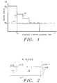
- Fig. 1 is a graph showing the rotor speed vs. time of prior art centrifugation methods.
- Fig. 2 is a diagram illustrating the mathematical division of a centrifuge tube to aid in the description of the numerical analysis of the present invention.
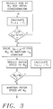
- Fig. 3 is a flowchart of rotor speed control in accordance with one aspect of the present invention.
- Fig. 4 is a graph showing rotor speed vs. time of rotor speed control in accordance with one aspect of the present invention.
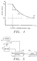
- Fig. 5 is a schematic diagram of a rotor and speed controller.
- One aspect of the present invention is a method which absolutely minimizes centrifugation time within the constraint of salt crystallization or precipitation in, for example, a cesium chloride ("CsCl") self-forming density gradient solution.
- CsCl cesium chloride
- the present invention can be practiced with other types of gradient solutions and in other applications such as rate zonal separation.
- the centrifuge tube used is a cylindrical test tube oriented with its axis horizontal during centrifugation. The analysis below can be applied to other types of centrifuge tubes of different geometry and orientation and other types of rotors.
- the solution 19 in the centrifuge tube 18 is divided into N slices beginning from the meniscus 17 of the solution.
- N can be any integer number, the value of which will determine the accuracy of the calculation and the computation time required.
- Each slice has a finite thickness and volume and is separated from adjacent slices by imaginary boundaries.
- J i-1,i sW 2 r i-1,i C i-1,i ⁇ - D v ⁇ C i-1,i
- i 1, ---,N
- J i-1,i the flux, or time rate of passage of particles per unit area across the boundary separating the (i-1)th and ith slices
- s the sedimentation coefficient of the particles
- W is the angular velocity of the rotor
- r i-1,i is the radial distance of the boundary separating the (i-1)th and ith slices measured from the axis of rotation
- C i-1,i ⁇ is the average concentration of particles in the (i-1)th and ith slices (expressed as number of particles per unit volume)
- D is the diffusion coefficient for the particles which depends on the size and shape of the particles, the viscosity of the solution and temperature
- vC i-1,i is the "gradient" of the concentration of particles at
- the speed W o that is required to make the flux J N-1,N into the bottom (Nth) slice equal to exactly zero is then calculated.
- the rotor speed is then reduced to this new speed W o thereby keeping the concentration in the bottom slice C N at or below (close to) the critical precipitation threshold value C crit .
- the rotor speed is similarly calculated and reduced so as to maintain the concentration C N in the bottom slice at or below (close to) precipitation concentration C crit or q x C crit for all time t>T c .
- the change in rotor speed with time required to maintain close to critical concentration is best illustrated by line 22 in Fig. 4.
- the rotor speed is maintained as close as is practical to the critical speed limit; higher speeds would cause precipitation of the gradient material.
- the smoothness of the curve 22 will depend on the frequency of successive iterations. In theory, a smooth line 20 can be obtained using a large N value and high speed processors.
- the flux J i-1,i across each boundary at each distance r i-1,i can be calculated.
- ⁇ C i-1,i is approximated as the difference of the concentrations (C i-1, C i ) across adjacent slices divided by a distance measured between the centers of the slices, which in the case of slices of equal thickness equals the thickness of a slice.
- concentrations are the same for each slice as in the case of a homogenous self-forming density gradient solution, e.g. cesium chloride.
- the total number of particles that travel across each boundary during the period ⁇ t is then simply given by: J i-1,i ⁇ A i-1,i ⁇ ⁇ t
- a i-1,i is the area of the boundary between the (i-1)th and ith slices. In the case of the test tube in the example shown in Fig. 2, this area will be the same for all boundaries except for the slices near the bottom of the tube.
- the total number of particles residing in a particular slice after period ⁇ t will be given by ⁇ the number of particles originally present ⁇ plus ⁇ the net number of particles flowing into that slice ⁇ . Since the geometry and thus the volume of the slice is known, the new concentration C i after period ⁇ t is given by the total number of particles in the slice divided by the slice volume.
- concentration values C i obtained for the preceding ⁇ t period are used to obtain the flux values for the current ⁇ t period, which in turn are used to obtain a new set of concentration values. This iterative process continues indefinitely until a user specified condition has been met.
- the condition specified is that the concentration in the Nth slice should be less than the concentration at which the density gradient solution will precipitate, and preferably within a margin of safety q.
- J N-1,N the flux through the boundary separating the (N-1)th and Nth slices
- W o the rotor speed which satisfies the zero flux condition
- C N-1,N ⁇ average concentration in the (N-1)th and Nth slices
- r N-1,N the radial distance of the boundary separating the (N-1)th and Nth slices measured from the axis of rotation
- r distance between midlines of the (N-1)th and Nth slices.
- the rotor is slowed down to the new speed W o .
- the method of the present invention provides complete automation in optimizing centrifugation (at absolute minimum operating time).
- the optimized time dependent rotor speed may be predicted through computer simulation and programmed into the control systems of centrifuges which run on variable speed motors, for example, the OptimaTM series ultracentrifuges developed and manufactured by Beckman Instruments, Inc.
- the line 22 in Fig. 4 may be approximated by line 20 which can be expressed as an analytical equation and programmed into the control system of the centrifuge to provide a fine control of the rotor speed.
- the centrifuge may be controlled under "real-time" calculation of the rotor speed.
- centrifugation can be carried out close to the optimum conditions represented by line 20 in Figure 4.
- a schematic diagram of the control system of the centrifuge is shown in Fig. 5.
- a variable speed motor 30 drives the rotor 32 within the chassis (not shown) of the centrifuge.
- the speed of the motor 30 is controlled by a microprocessor controller 34 in accordance with the technique heretofore described.
- a speed sensor 36 provides feedback of the rotor speed to the controller 34.
- Relevant input data such as initial concentration profile, constants and tube geometry are input through user interface 38.
- the present invention is not limited to a particular type of rotor or centrifuge tube. Any combination of rotor, centrifuge tube, loading configuration of the density gradient solution can be simulated and controlled using the method of the present invention.
- the thickness and the boundary area may be different for each slice for tubes with special geometry.
- the time interval ⁇ t between each iteration may be different for different rotors and/or different time segments in the process; for example it is preferred to have very small time intervals for the first few iterations to avoid singularities in the numerical integration.
- the flux analysis begins at a given initial rotor speed. In an actual centrifugation run, however the rotor speeds up from rest to such "initial speed". However, the time taken to do this is negligible compared to the total run time and the transient sedimentation and diffusion flows during this start-up period is negligible. The start-up period therefore can be ignored to a good approximation.
Description
- The present invention relates to centrifugation and more particularly to the control of rotor speed for controlling concentration variation in a centrifuge chamber.
- Essentially, centrifugation is a process for separating particles suspended in a solution. In biological applications, the particles are usually macromolecules, cells, DNA fragments, etc. There are two primary types of centrifuge procedures, one being "preparative" which is to isolate specific particles, and the other being "analytical" which involves measuring the physical properties of a sedimenting particle.
- The device used for centrifugation is a centrifuge which includes a rotor that supports several containers or centrifuge tubes, of sample solution for rotation about a common spin axis. As the rotor spins in the centrifuge, centrifugal force is applied to each particle in the sample solution; each particle will sediment at a rate which is proportional to the centrifugal force applied. The viscosity of the sample solution and the physical properties of the particle also affect the sedimentation rate of each individual particle. For a given centrifugal force, density and liquid viscosity, the sedimentation rate of the particle is proportional to its size (molecular weight), and to the difference between its density and the density of the solution.
- One of many methods of centrifugal separation is differential centrifugation, or pelleting. In this method, the centrifuge tube is filled initially with a uniform mixture of sample solution. Through centrifugation, one obtains a separation of two fractions including a pellet containing the sedimented material, and supernatant solution of the unsedimented material. The pellet is a mixture of all of the sedimented components.
- Another method of separation is by density gradient centrifugation, a method somewhat more complicated than differential centrifugation, but one which has compensating advantages. Not only does the density gradient method permit the complete separation of several or all of the components in a mixture according to their densities, but it also permits analytical measurements to be made. The density gradient method involves a supporting column of "density gradient" fluid whose density increases toward the bottom of the tube. The density gradient fluid consists of a suitable low molecular weight solute in a solvent in which the sample particles can be suspended.
- There are two widely used methods of density gradient centrifugation: rate zonal and isopycnic. In the rate zonal technique, a sample solution containing particles to be separated is layered on a preformed gradient column. Under centrifugal force, the particles will begin sedimenting through the gradient toward the bottom of the centrifuge tube and separate into zones along the tube, each zone consisting of particles characterized by their sedimentation rate. The zones continue to move down the tube with time. To achieve a rate zonal separation, the density of the sample particles must be greater than the density at any specific position along the gradient column, in order for the particles to be able to continue to move down the tube. The run must be terminated before any of the separated zones reaches the bottom of the tube. Otherwise, two or more separated zones will mix at the bottom of the tube.
- In the isopycnic technique, the density gradient column encompasses the whole range of densities of the sample particles. Each particle will sediment or float toward a position in the centrifuge tube at which the gradient density is equal to its own density, and there it will remain in equilibrium. The isopycnic technique, therefore, separates particles into zones on the basis of their density differences.
- Density gradients can be formed manually by layering density gradient material of gradually decreasing densities in the centrifuge tube. In the isopycnic procedure, it is sometimes easier to start with a uniform solution of the sample and the gradient material. Under the influence of centrifugal force, the gradient material redistributes in the tube so as to form the required concentration (and density) gradient. This is often referred to as the self-generating gradient technique in which a continuous density gradient is formed when the diffusion of the gradient material towards the rotor spin axis balances the sedimentation away from the spin axis at each radial location along the centrifuge tube. Meanwhile, sample particles, which are initially distributed throughout the tube, sediment or float to their isopycnic positions. This self-generating gradient technique often requires long hours of centrifugation.
- Generally, centrifugal separation can be effected in less time by centrifuging at higher rotor angular velocity. However, it is limited by the condition that the centrifugal force of the mass of the rotor and its contents at high rotor velocity not exceed the yield stress of the rotor. Furthermore, the rotor angular velocity is also limited by the condition that the solution of the gradient material not attain saturation at the outermost location of the centrifuge tube at any time during centrifugation. This is to avoid the possibility of salt crystallization or precipitation, which involves a process of accumulation of mass as the salt transforms from the dissolved to solid crystalline phase. This can lead to possible rotor failure due to excessive stress on the rotor by the dense crystalline salt.
- Rotor manufacturers typically provide manuals that contain information regarding the top speed at which the rotor can be safely run for an indefinite period of time, for a given loading concentration, without reaching the gradient salt precipitation threshold. Referring to Fig. 1, Wp represents the speed at which precipitation will never occur for an indefinite period of time for a particular loading density. In the past, a centrifugation run has been carried out at a single speed Wp to safely operate within the precipitation threshold (line 12). A more efficient method would be to run the rotor at the highest speed Wy within the yield stress limit of the rotor, until precipitation is expected to occur at time Tc at which time the rotor speed is reduced to the value Wp which would then not allow precipitation to occur for an indefinite period of time (line 14). Using this method, the total elapsed centrifugation time required for a particular state of separation is less than that in the case of the single speed run. One can also compare the efficiency of the two methods by comparing the integrals of W under the
operating lines - Recently, a new technique was proposed by Chulay et al. in U.S. Patent 4,941,868 which utilizes a dynamic simulation of gradient salt sedimentation to predict the elapsed time at which the precipitation threshold is reached for a number of discrete speeds. The technique requires several speed reductions in coarse steps (line 16) during a run to maintain the gradient salt density within the precipitation threshold. The reduced speeds are designated by the manufacturer and are selected via trial and error to decrease run time. This technique significantly increases the average speed of the rotor above that found in both of the previously described techniques. The amount of time required to attain separation is therefore substantially decreased.
- While the technique described in the Chulay et al. patent has been found to be efficient, the process for finding
curve 16 is not automated; furthermore the rotor speed has not been optimized to produce the shortest run time. In recent days when centrifugation has quite a few competing technologies for macromolecular separation, automated minimization of the amount of time required for centrifugal separations has become commercially important. Because the technique described in the Chulay et al. patent requires a trial and error approach to selecting the speeds at which centrifugation is to be run, the highest possible speed at a particular elapsed time very often has not been selected. - FR 2500629 discloses an apparatus for determining particle distribution as a function of size in a relatively limited time by simultaneously increasing the rotational speed of a centrifuge rotor and reducing the distance from the rotational axis at which measurements are made. The patent describes how increasing rotational speed of the centrifuge allows measuring the particle distribution of particles having very small diameters, and describes how the radial position, with respect to the rotational axis, of these particles may be determined as a function of rotational speed and time. However, the particular problems of controlling a net flux across a volume element boundary, or the control of the ratio of net fluxes across two such boundaries, are not addressed. Further, the effect of time varying the rotational speeds so as to prevent precipitation of the solute is not addressed.
- JP-A-58160843 discloses a similar apparatus to that described above and advocates constantly increasing a rotation speed of a centrifuge over time to shorten the time needed to measure the particle size distribution of a solution. However, this document does not address the particular problems of controlling a net flux across a volume element boundary, or the control of the ratio of net fluxes across two such boundaries. Further, the effect of time varying the rotational speed so as to prevent precipitation in any given volume element is not addressed.
- The present invention is directed to a method of controlling the rotor speed for centrifugation of a sample solution in accordance with a user specified sedimentation and diffusion to obtain the desired concentration variation in the centrifuge chamber. The rotor speed is automatically controlled to vary practically continuously with time in the method so as to avoid precipitation of the sample solution.
- In one aspect of the present invention, the method can be utilized to absolutely minimize the total amount of time for the separation of macromolecules in a density gradient forming solution. Minimizing the separation time is achieved by commencing centrifugation at an angular velocity that is less than but approximately equal to the maximum angular velocity of the rotor. The maximum rotor speed is maintained throughout the centrifugation run subject to a rotor stress constraint on the concentration of the density gradient solution at the outer most location of the sample chamber in the rotor.
- Other applications of the method include control of movements of macromolecules by varying rotor speed to obtain a desired time dependent concentration, and control of movements of two or more species by varying rotor speed to obtain a desired concentration ratio between the species at a desired radial location.
- According to one aspect of the present invention there is provided a method of centrifuging a sample solution comprising the steps of:
- supporting a sample solution in a rotor of a centrifuge, said sample solution having at least one solute component therein,
- rotating said sample solution in said rotor at a time dependent variable rotational speed w about a rotational axis, being further characterized by determining and automatically adjusting the rotational speed w as a function of time in order to avoid precipitation of said sample solution independence on the sedimentation and diffusion behaviour of said solute component as a function of rotational speed and time.
- According to a further aspect of the present invention there is provided a centrifuge apparatus comprising:
- a rotor to support a sample solution for rotation about a rotational axis, said sample solution having at least one solute component therein,
- a drive to rotate said sample solution at a time dependent variable rotational speed about the rotational axis, being further characterized by a controller to adjust a rotational speed as a function of time to avoid precipitation of said solute component of said sample solution independence on the sedimentation and diffusion behaviour of said solute component as a function of rotational speed, time and radial position in said sample solution relative to said rotational axis.
- Fig. 1 is a graph showing the rotor speed vs. time of prior art centrifugation methods.
- Fig. 2 is a diagram illustrating the mathematical division of a centrifuge tube to aid in the description of the numerical analysis of the present invention.
- Fig. 3 is a flowchart of rotor speed control in accordance with one aspect of the present invention.
- Fig. 4 is a graph showing rotor speed vs. time of rotor speed control in accordance with one aspect of the present invention.
- Fig. 5 is a schematic diagram of a rotor and speed controller.
- The following description is of the best presently contemplated mode of carrying out the invention. This description is made for the purpose of illustrating the general principles of the invention and should not be taken in a limiting sense. The scope of the invention is best determined by reference to the appended claims.
- One aspect of the present invention is a method which absolutely minimizes centrifugation time within the constraint of salt crystallization or precipitation in, for example, a cesium chloride ("CsCl") self-forming density gradient solution. It will be appreciated that the present invention can be practiced with other types of gradient solutions and in other applications such as rate zonal separation. To simplify the description of the present invention, the centrifuge tube used is a cylindrical test tube oriented with its axis horizontal during centrifugation. The analysis below can be applied to other types of centrifuge tubes of different geometry and orientation and other types of rotors.
- Referring to Fig. 2, the
solution 19 in thecentrifuge tube 18 is divided into N slices beginning from themeniscus 17 of the solution. N can be any integer number, the value of which will determine the accuracy of the calculation and the computation time required. Each slice has a finite thickness and volume and is separated from adjacent slices by imaginary boundaries. The governing equation for sedimentation and diffusion is a well known precursor of the Lamm equation:

- Referring to Figs. 3 and 4 the method for the determination of the optimal rotor speed that will result in the shortest amount of time required for density gradient separations is first outlined. Centrifugation is started at the maximum speed Wy permissible for the particular rotor and average density of the solution. The maximum speed Wy is determined from rotor yield stress specifications provided by the rotor manufacturers. Centrifugation is continued at that speed until the time t=Tc when the concentration CN of the gradient salt, e.g. CsCl, in the bottom of the tube reaches the critical precipitation threshold value Ccrit or a value within a desired margin of safety (q x Ccrit where 0<q<1, and in practice q is close to 1). The speed Wo that is required to make the flux JN-1,N into the bottom (Nth) slice equal to exactly zero is then calculated. The rotor speed is then reduced to this new speed Wo thereby keeping the concentration in the bottom slice CN at or below (close to) the critical precipitation threshold value Ccrit. At each iteration the rotor speed is similarly calculated and reduced so as to maintain the concentration CN in the bottom slice at or below (close to) precipitation concentration Ccrit or q x Ccrit for all time t>Tc. The change in rotor speed with time required to maintain close to critical concentration is best illustrated by
line 22 in Fig. 4. The rotor speed is maintained as close as is practical to the critical speed limit; higher speeds would cause precipitation of the gradient material. The smoothness of thecurve 22 will depend on the frequency of successive iterations. In theory, asmooth line 20 can be obtained using a large N value and high speed processors. - The premise of this particular aspect of the present invention is based on the observation that after the Nth slice reaches the critical concentration Ccrit or q x Ccrit at t=Tc, if the rotor speed is controlled such that the net flux of gradient salt into this slice is zero, then the concentration of the gradient salt at the bottom of the tube cannot ever change after t=Tc. Centrifugation can thus be carried out at the highest speeds (shortest time) without fear of precipitation problems.
- The steps for obtaining concentration and rotor speed values will now be described in detail. The computer algorithm associated with these steps, however, will not be described since it is merely an exercise of computational programming skills involving conventional numerical computation techniques. A portion of the algorithm is substantially similar to the algorithm used in U.S. Patent 4,941,868, commonly assigned to the assignee of the present application, for transient analysis of centrifugal separation. The relevant portions of said application are incorporated by reference herein.
- Given the initial concentrations in each slice, the initial rotor speed Wy consistent with rotor yield stress constraint for the particular average fluid density, and the diffusion and sedimentation constants, the flux Ji-1,i across each boundary at each distance ri-1,i can be calculated. As is consistent with finite difference approximation, ∇Ci-1,i is approximated as the difference of the concentrations (Ci-1,Ci) across adjacent slices divided by a distance measured between the centers of the slices, which in the case of slices of equal thickness equals the thickness of a slice. For initial concentrations in each slice, the simplest example will be the case where the concentrations are the same for each slice as in the case of a homogenous self-forming density gradient solution, e.g. cesium chloride.
- The total number of particles that travel across each boundary during the period Δt is then simply given by:

- By obtaining the flux at each and every one of the boundaries and subsequently applying the just described steps for calculating the concentrations, one can obtain the new concentration values at any time t, thereby modelling the concentrations of the particles.
- The same calculations are repeated after each period Δt. Each iteration, the concentration values Ci obtained for the preceding Δt period are used to obtain the flux values for the current Δt period, which in turn are used to obtain a new set of concentration values. This iterative process continues indefinitely until a user specified condition has been met.
- For purposes of controlling rotor speed to avoid precipitation of gradient-forming salt, the condition specified is that the concentration in the Nth slice should be less than the concentration at which the density gradient solution will precipitate, and preferably within a margin of safety q. Once this condition has been met at t=Tc, the next iteration at Tc + Δt requires that the flux JN-1,N into the Nth slice is set to equal exactly zero. One thus solves for Wo, a unique rotor speed which will satisfy J = 0. In particular, the following equation for the rotor speed, Wo, is solved:


- The rotor is slowed down to the new speed Wo. As before, the new fluxes and concentration values for all the slices are next calculated, based this time on the new speed value found from J=0. Thereafter for each iteration a new rotor speed is calculated. Theoretically, the rotor speed should change (decrease) at each iteration following the first instance at t=Tc when the critical concentration criterion Ccrit has been met, until Wp (the speed at which precipitation will never occur for an indefinite period of time) has been asymptotically approached. It is understood that the process may be terminated at any time before or after Wp has been reached in accordance with a user specified condition, e.g. a specified elapsed run time.
- It can be appreciated that the method of the present invention provides complete automation in optimizing centrifugation (at absolute minimum operating time). The optimized time dependent rotor speed may be predicted through computer simulation and programmed into the control systems of centrifuges which run on variable speed motors, for example, the Optima™ series ultracentrifuges developed and manufactured by Beckman Instruments, Inc. The
line 22 in Fig. 4 may be approximated byline 20 which can be expressed as an analytical equation and programmed into the control system of the centrifuge to provide a fine control of the rotor speed. Alternatively, the centrifuge may be controlled under "real-time" calculation of the rotor speed. Depending on the resolution of the motor speed control, centrifugation can be carried out close to the optimum conditions represented byline 20 in Figure 4. - A schematic diagram of the control system of the centrifuge is shown in Fig. 5. A
variable speed motor 30 drives therotor 32 within the chassis (not shown) of the centrifuge. The speed of themotor 30 is controlled by amicroprocessor controller 34 in accordance with the technique heretofore described. Aspeed sensor 36 provides feedback of the rotor speed to thecontroller 34. Relevant input data such as initial concentration profile, constants and tube geometry are input throughuser interface 38. - The present invention is not limited to a particular type of rotor or centrifuge tube. Any combination of rotor, centrifuge tube, loading configuration of the density gradient solution can be simulated and controlled using the method of the present invention.
- The thickness and the boundary area may be different for each slice for tubes with special geometry. To improve the resolution and accuracy of the process, the time interval Δt between each iteration may be different for different rotors and/or different time segments in the process; for example it is preferred to have very small time intervals for the first few iterations to avoid singularities in the numerical integration.
- It is noted that in the foregoing description of the method, the flux analysis begins at a given initial rotor speed. In an actual centrifugation run, however the rotor speeds up from rest to such "initial speed". However, the time taken to do this is negligible compared to the total run time and the transient sedimentation and diffusion flows during this start-up period is negligible. The start-up period therefore can be ignored to a good approximation. One can of course include flux analysis of the start-up period for marginal improvement in precision.
- Using similar flux analysis as described above, it is possible to specify the condition that the concentration of a component of the sample solution in any slice should vary as a specified function of time f(t) where


- While the invention has been described with respect to the preferred embodiments in accordance therewith, it will be apparent to those skilled in the art that various modifications and improvements may be made without departing from the scope of the invention. Accordingly, it is to be understood that the invention is not to be limited by the specific illustrated embodiments, but only by the scope of the appended claims.
Claims (20)
- A method of centrifuging a sample solution (19) comprising the steps of:supporting a sample solution in a rotor of a centrifuge, said sample solution having at least one solute component therein,rotating said sample solution in said rotor at a time dependent variable rotational speed w about a rotational axis, being further characterized by determining and automatically adjusting the rotational speed w as a function of time in order to avoid precipitation of said sample solution independence on the sedimentation and diffusion behaviour of said solute component as a function of rotational speed and time.
- The method of claim 1 wherein said sedimentation and diffusion behaviour includes time-dependent concentrations Ci (i=1,2,...,N) of the solute component at radial positions ri in said sample solution relative to said rotational axis and time-dependent flux Ji, i+1 of said solute component from each said radial position ri to a radially adjacent position ri+1 in said sample solution, and further comprising the steps of:specifying a set of conditions on said sedimentation and diffusion behaviour which are to be satisfied, said set of conditions including at least one condition on one of said concentrations and flux of said solute component which is to be satisfied of at least one radial position in said sample solution in order to avoid precipitation of said solute component from said sample solution, andsimulating said sedimentation and diffusion behaviour of said solute component of said sample solution as a function of rotational speed and time, said simulating including computing, in each of a plurality of successive time intervals, the flux Ji,i+1 as a function of rotational speed w of said solute component during the time interval between each pair of radially adjacent positions ri and ri+1 in said sample solution, and the corresponding concentration Ci of said solute component during the next successive time interval at each radial position ri in said sample solution that results from said flux,wherein said step of determining and automatically adjusting the rotational speed w includes determining, in each of said plurality of successive time intervals, from said simulated sedimentation and diffusion behaviour, a maximum rotational speed during said time interval that satisfies said specified set of conditions, and adjusting said time dependent variable rotational speed to substantially equal to the latest maximum rotational speed that has been determined.
- The method of claim 1 wherein said sample solution includes a solute and a solvent contained in a centrifuge tube, and further including the step of dividing, for computational purposes, the contents of the centrifuge tube into a plurality of slice volumes with each of said plurality of slice volumes being approximately a fixed radial distance r=ri (i=1,2,...,N) from the rotational axis, where one of said plurality of slice volumes has the largest associated radial distance r=rN from the rotational axis, and the rotating step includes rotating a centrifuge tube about its rotational axis at an angular velocity w = w(t) as a function of time t to produce a flux Ji,i+1(t) of solute particles between adjacent slice volumes so that concentration Ci(t) of solute in a slice volume varies with time, and said determining step includes automatically adjusting the angular velocity w(t) as a function of time t so that CN(t) of the net flux of the solute into the slice volume with associated radial distance r=rN computed as the angular velocity w(t), for rotation of the centrifuge tubes, increases with time to a predetermined critical Ccrit at a determinable time t=Tc and does not increase above the value Ccrit for any time t greater than Tc.
- The method of claim 1 with said sample solution comprising a solute and a solvent contained in a centrifuge tube and further including a step of dividing, for computational purposes, the contents of the centrifuge tube into a plurality of slice volume elements with each of said plurality of slice volume elements being approximately a fixed radial distance r=ri (i=1,2,...,N) from the rotational axis, where at least one of said plurality of slice volume elements has a largest associated radial distance r=rN from the rotational axis, wherein said step of rotating said sample solution in said rotor includes rotating the centrifuge tube about its rotational axis at an angular velocity w = w(t) as a function of time t to produce a time dependent flux Ji-1,i of solute particles between adjacent slice volume elements ΔVi-1 and ΔVi and a time dependent flux Ji,i+1 of solute particles between adjacent slice volume elements ΔVi and ΔVi+1 so that the concentration Ci(t) of solute in a slice volume element ΔVi varies with time, and said determining step include automatically adjusting the angular velocity w(t) as a function of time t so that the net flux of solute particles into the volume element ΔVi, computed using the angular velocity w(t) for rotation of centrifuge tube, varies with time as a predetermined function f(t) of time.
- The method of claim 1 with said sample solution comprising first and second solutes in a solvent contained in a centrifuge tube and further including the step of dividing, for computational purposes, the contents of the centrifuge tube into a plurality of slice volumes, with each of said plurality of volumes being approximately a fixed radial distance r=ri (i=1,2,...,N) from the spin axis, where at least one of said plurality of slice volumes has a largest associated radial distance r=rN from the rotational axis, wherein said step of rotating said sample solution in a rotator includes rotating the centrifuge tube about its rotational axis at an angular velocity w = w(t) as a function of time t to produce a net flux of first solute particles A into a predetermined slice volume, and a net flux of second solute particles B into the same slice volume, said determining step including automatically adjusting the angular velocity w(t) as a function of time t so that the ratio of the net flux of the first solute particles A to the net flux of the second particles B into the predetermined slice volume computed using the angular velocity w(t) for rotation of the centrifuge tube, varies with time as a predetermined function f(t) of time.
- The method of claim 2 wherein said set of conditions includes a concentration-independent condition that said rotational speed w have an upper limit for which a yield stress limit of said rotor is not exceeded.
- The method of claim 2 wherein said at least one condition is that for i=k the concentration Ck of said solute component at a specified radial position rk in said sample solution relative to said rotating axis vary according to a particular specified function of time f(t).
- The method of claim 7 wherein i=k=N, where rN is a position in said sample solution farthest from said rotational axis.
- The method of claim 8 wherein for i=N the concentration CN, defined by said function f(t), increases for time 0<t<Tc until said concentration CN reaches a value of q x Ccrit in a time interval Tc, where q is a specified safety margin with 0<q≤1 and Ccrit is a critical concentration at which said solute component precipitates from said sample solution, and wherein said concentration CN is substantially constant at q x Ccrit for time intervals t>Tc, whereby said solute component is prevented from precipitating.
- The method of claim 2 wherein said at least one condition is that for i=k the flux Jk-1,k of said solute component from a specified radial position rk-1 to a radially adjacent position rk in said sample solution vary according to a particular function of time f(t).
- The method of claims 7 or 10 wherein i=k=N where rN is the position in said sample solution furthest from said rotational axis.
- The method of claim 11 wherein for i=N the flux JN-1,N, defined by said function f(t), is substantially zero for time t>Tc after a time interval Tc in which the concentration CN in said solute component at said specified position rN reaches a value of q x Ccrit, where q is a specified safety margin with 0<q≤1 and Ccrit is a critical concentration at which said solute component precipitates from said sample solution.
- The method of claim 1 further comprising the step of causing said angular velocity w(t) to have an initial value that is less than, but approximately equal to, the maximum angular velocity w = w y permitted to preserve the structural integrity of said rotor mechanism.
- The method of claim 1 further comprising the step of holding said angular velocity w(t) approximately constant at w(t) = w y for all times t up to said time t=Tc.
- A centrifuge apparatus comprising:a rotor (32) to support a sample solution (19) for rotation about a rotational axis, said sample solution having at least one solute component therein,a drive (30) to rotate said sample solution at a time dependent variable rotational speed about the rotational axis, being further characterized by a controller (34) to adjust a rotational speed as a function of time to avoid precipitation of said solute component of said sample solution independence on the sedimentation and diffusion behaviour of said solute component as a function of rotational speed, time and radial position in said sample solution relative to said rotational axis.
- The apparatus of claim 15 wherein said sample solution includes a solvent and a solute with the rotor rotating the sample solution about the rotational axis, the rotor having at least one slice volume containing said sample solution with a radial distance rN from the rotational axis that is at least as large as a radial distance ri (i=1,2,...,N) from the rotational axis of any other slice volume of the rotor, with the drive, connected to the rotor, for rotating the rotor about the rotational axis with a time varying angular velocity w = w(t) to produce a flux of solute particles between different portions of the rotor, wherein the controller is connected to the drive for automatically adjusting the angular velocity w(t) as a function of time t so the net flux Ji of solute particles into the any other slice volume varies as a predetermined function of time f(t).
- The apparatus of claim 16 wherein the controller adjusts the angular velocity w(t) as a function of time t so that concentration CN of solute particles in the slice volume with the radial distance rN increases with time to a predetermined Ccrit at a determinable time t=Tc and does not increase above the value Ccrit for any time greater than Tc.
- The apparatus of claim 16 with said sample solution including a solvent and first and second solutes, the rotor having a plurality of slice volumes at various radial distances containing a sample solution whose radial distance rN from the rotational axis is at least as large as the radial distance ri from the rotational axis of any other volume element of the rotor, wherein said controller is connected to the drive for automatically adjusting the angular velocity w(t) as a function of time t so that the ratio of the net flux of first solute particles into a predetermined slice volume to the net flux of second solute particles into the same predetermined volume element varies as a predetermined function of time f(t).
- The apparatus of claims 16, 17 or 18, wherein said controller causes said angular velocity w(t) to have an initial value that is less than, but approximately equal to, the maximum angular velocity w = w y permitted to preserve the structural integrity of said rotor mechanism.
- The apparatus of claims 16, 17 or 18, wherein said controller causes said angular velocity w(t) to be approximately constant at w(t) = w y for all times t up to said time t=Tc.
Applications Claiming Priority (2)
| Application Number | Priority Date | Filing Date | Title |
|---|---|---|---|
| US49270990A | 1990-03-12 | 1990-03-12 | |
| US492709 | 1990-03-12 |
Publications (3)
| Publication Number | Publication Date |
|---|---|
| EP0447060A2 EP0447060A2 (en) | 1991-09-18 |
| EP0447060A3 EP0447060A3 (en) | 1992-07-01 |
| EP0447060B1 true EP0447060B1 (en) | 1996-04-10 |
Family
ID=23957331
Family Applications (1)
| Application Number | Title | Priority Date | Filing Date |
|---|---|---|---|
| EP19910301561 Expired - Lifetime EP0447060B1 (en) | 1990-03-12 | 1991-02-26 | Optimal centrifugal separation |
Country Status (3)
| Country | Link |
|---|---|
| EP (1) | EP0447060B1 (en) |
| JP (1) | JPH0739790A (en) |
| DE (1) | DE69118573T2 (en) |
Families Citing this family (4)
| Publication number | Priority date | Publication date | Assignee | Title |
|---|---|---|---|---|
| CH685312A5 (en) * | 1993-05-03 | 1995-05-31 | Diag Human Ag | Apparatus for blood analysis. |
| DE19542225B4 (en) * | 1995-11-01 | 2011-05-26 | L.U.M. Gmbh | Method and device for determining rheological and mechanical substance characteristics |
| GB9606559D0 (en) * | 1996-03-28 | 1996-06-05 | Zynocyte Ltd | Apparatus and method for analysing blood samples |
| JP4247390B2 (en) * | 2003-03-31 | 2009-04-02 | 独立行政法人産業技術総合研究所 | Fine particle classification method and apparatus |
Family Cites Families (3)
| Publication number | Priority date | Publication date | Assignee | Title |
|---|---|---|---|---|
| FR2500629A1 (en) * | 1981-07-22 | 1982-08-27 | Astier Jean | Centrifugal granulometric analysis appts. - uses centrifugal discs of which speed increases and measurement distance from axis of disc decreases w.r.t. time |
| JPS58160843A (en) * | 1982-03-18 | 1983-09-24 | Horiba Ltd | Centrifugal measuring method of particle size distribution |
| DE3818407A1 (en) * | 1988-05-31 | 1989-12-07 | Hermle Kg Berthold | DEVICE FOR CONTROLLING THE OPERATION OF A CENTRIFUGE |
-
1991
- 1991-02-26 EP EP19910301561 patent/EP0447060B1/en not_active Expired - Lifetime
- 1991-02-26 DE DE1991618573 patent/DE69118573T2/en not_active Expired - Fee Related
- 1991-03-12 JP JP7040891A patent/JPH0739790A/en active Pending
Also Published As
| Publication number | Publication date |
|---|---|
| EP0447060A3 (en) | 1992-07-01 |
| DE69118573D1 (en) | 1996-05-15 |
| EP0447060A2 (en) | 1991-09-18 |
| DE69118573T2 (en) | 1996-08-29 |
| JPH0739790A (en) | 1995-02-10 |
Similar Documents
| Publication | Publication Date | Title |
|---|---|---|
| US5171206A (en) | Optimal centrifugal separation | |
| US5370599A (en) | Terminating centrifugation on the basis of the mathematically simulated motions of solute band-edges | |
| US4263010A (en) | Control method and apparatus for crystallizer process control | |
| US20060100838A1 (en) | Method and apparatus for producing a biomaterial product | |
| US20060258524A1 (en) | Centrifuge with removable core for scalable centrifugation | |
| EP0447060B1 (en) | Optimal centrifugal separation | |
| US4736311A (en) | Particle size distribution measuring apparatus | |
| JP4845159B2 (en) | Ultracentrifuge user interface | |
| EP0408262B1 (en) | Optimum centrifugal separation of particles by transient analysis and feedback | |
| US5675519A (en) | Apparatus and method for controlling centrifugal separator and centrifugation simulation method and centrifugal separator | |
| Langlois et al. | Digital simulation of flow patterns in the czochralski crystal-pulling process | |
| CA2025946C (en) | Temperature controlling means | |
| Berman et al. | Two-fluid spin-up in a centrifuge | |
| EP0198767B1 (en) | Method and apparatus for sequential fractionation | |
| Chamberlain et al. | An experimental investigation of convection in a rotating sphere subject to time varying thermal boundary conditions | |
| Fritsch | Properties of various rotors used for zone centrifugation | |
| Clark et al. | A quantitative test of Zimm's model for the rotor‐speed‐department sedimentation of linear DNA molecules | |
| JP3324329B2 (en) | Centrifuge simulation | |
| Chatelier | A parameterized overspeeding method for the rapid attainment of low-speed sedimentation equilibrium | |
| Attri et al. | An automated method for determination of the sedimentation coefficient of macromolecules using a preparative centrifuge | |
| Gandhi et al. | Centrifugation | |
| Bylund et al. | Prediction of centrifugation times for equilibrium and velocity sedimentation on various gradients | |
| JP3761034B2 (en) | centrifuge | |
| Bradford et al. | Nongeostrophic baroclinic instability in a two-fluid layer rotating system | |
| Garnier et al. | Questions raised about material processing in a centrifuge: lessons derived from the LCPC's experience |
Legal Events
| Date | Code | Title | Description |
|---|---|---|---|
| PUAI | Public reference made under article 153(3) epc to a published international application that has entered the european phase |
Free format text: ORIGINAL CODE: 0009012 |
|
| AK | Designated contracting states |
Kind code of ref document: A2 Designated state(s): CH DE FR GB IT LI |
|
| PUAL | Search report despatched |
Free format text: ORIGINAL CODE: 0009013 |
|
| AK | Designated contracting states |
Kind code of ref document: A3 Designated state(s): CH DE FR GB IT LI |
|
| 17P | Request for examination filed |
Effective date: 19921028 |
|
| 17Q | First examination report despatched |
Effective date: 19940314 |
|
| GRAA | (expected) grant |
Free format text: ORIGINAL CODE: 0009210 |
|
| ITF | It: translation for a ep patent filed |
Owner name: BARZANO' E ZANARDO MILANO S.P.A. |
|
| AK | Designated contracting states |
Kind code of ref document: B1 Designated state(s): CH DE FR GB IT LI |
|
| REG | Reference to a national code |
Ref country code: CH Ref legal event code: NV Representative=s name: BOVARD AG PATENTANWAELTE |
|
| REF | Corresponds to: |
Ref document number: 69118573 Country of ref document: DE Date of ref document: 19960515 |
|
| ET | Fr: translation filed | ||
| PGFP | Annual fee paid to national office [announced via postgrant information from national office to epo] |
Ref country code: GB Payment date: 19970106 Year of fee payment: 7 |
|
| PGFP | Annual fee paid to national office [announced via postgrant information from national office to epo] |
Ref country code: FR Payment date: 19970211 Year of fee payment: 7 |
|
| PLBE | No opposition filed within time limit |
Free format text: ORIGINAL CODE: 0009261 |
|
| STAA | Information on the status of an ep patent application or granted ep patent |
Free format text: STATUS: NO OPPOSITION FILED WITHIN TIME LIMIT |
|
| PGFP | Annual fee paid to national office [announced via postgrant information from national office to epo] |
Ref country code: DE Payment date: 19970224 Year of fee payment: 7 |
|
| 26N | No opposition filed | ||
| PGFP | Annual fee paid to national office [announced via postgrant information from national office to epo] |
Ref country code: CH Payment date: 19970422 Year of fee payment: 7 |
|
| PG25 | Lapsed in a contracting state [announced via postgrant information from national office to epo] |
Ref country code: GB Free format text: LAPSE BECAUSE OF NON-PAYMENT OF DUE FEES Effective date: 19980226 |
|
| PG25 | Lapsed in a contracting state [announced via postgrant information from national office to epo] |
Ref country code: LI Free format text: LAPSE BECAUSE OF NON-PAYMENT OF DUE FEES Effective date: 19980228 Ref country code: FR Free format text: THE PATENT HAS BEEN ANNULLED BY A DECISION OF A NATIONAL AUTHORITY Effective date: 19980228 Ref country code: CH Free format text: LAPSE BECAUSE OF NON-PAYMENT OF DUE FEES Effective date: 19980228 |
|
| GBPC | Gb: european patent ceased through non-payment of renewal fee |
Effective date: 19980226 |
|
| REG | Reference to a national code |
Ref country code: CH Ref legal event code: PL |
|
| PG25 | Lapsed in a contracting state [announced via postgrant information from national office to epo] |
Ref country code: DE Free format text: LAPSE BECAUSE OF NON-PAYMENT OF DUE FEES Effective date: 19981103 |
|
| REG | Reference to a national code |
Ref country code: FR Ref legal event code: ST |
|
| PG25 | Lapsed in a contracting state [announced via postgrant information from national office to epo] |
Ref country code: IT Free format text: LAPSE BECAUSE OF NON-PAYMENT OF DUE FEES;WARNING: LAPSES OF ITALIAN PATENTS WITH EFFECTIVE DATE BEFORE 2007 MAY HAVE OCCURRED AT ANY TIME BEFORE 2007. THE CORRECT EFFECTIVE DATE MAY BE DIFFERENT FROM THE ONE RECORDED. Effective date: 20050226 |