EP0446765A1 - Rangée découpe avec discontinuités pour trépan de forage - Google Patents
Rangée découpe avec discontinuités pour trépan de forage Download PDFInfo
- Publication number
- EP0446765A1 EP0446765A1 EP91103334A EP91103334A EP0446765A1 EP 0446765 A1 EP0446765 A1 EP 0446765A1 EP 91103334 A EP91103334 A EP 91103334A EP 91103334 A EP91103334 A EP 91103334A EP 0446765 A1 EP0446765 A1 EP 0446765A1
- Authority
- EP
- European Patent Office
- Prior art keywords
- discontinuity
- drill bit
- array
- cutting
- discontinuities
- Prior art date
- Legal status (The legal status is an assumption and is not a legal conclusion. Google has not performed a legal analysis and makes no representation as to the accuracy of the status listed.)
- Granted
Links
- 238000005520 cutting process Methods 0.000 title claims abstract description 67
- 238000003491 array Methods 0.000 claims abstract description 38
- 239000011159 matrix material Substances 0.000 claims description 28
- 230000015572 biosynthetic process Effects 0.000 claims description 15
- 238000005553 drilling Methods 0.000 claims description 6
- 230000001154 acute effect Effects 0.000 claims 4
- 239000010432 diamond Substances 0.000 description 13
- 238000005755 formation reaction Methods 0.000 description 13
- 230000035882 stress Effects 0.000 description 13
- 229910003460 diamond Inorganic materials 0.000 description 11
- 239000011230 binding agent Substances 0.000 description 10
- UONOETXJSWQNOL-UHFFFAOYSA-N tungsten carbide Chemical compound [W+]#[C-] UONOETXJSWQNOL-UHFFFAOYSA-N 0.000 description 9
- 239000000843 powder Substances 0.000 description 7
- 230000008646 thermal stress Effects 0.000 description 7
- 239000000956 alloy Substances 0.000 description 6
- 229910045601 alloy Inorganic materials 0.000 description 6
- 238000000034 method Methods 0.000 description 5
- 238000000576 coating method Methods 0.000 description 4
- 239000000463 material Substances 0.000 description 4
- 230000032798 delamination Effects 0.000 description 3
- 230000008595 infiltration Effects 0.000 description 3
- 238000001764 infiltration Methods 0.000 description 3
- 229910052751 metal Inorganic materials 0.000 description 3
- 239000002184 metal Substances 0.000 description 3
- RYGMFSIKBFXOCR-UHFFFAOYSA-N Copper Chemical compound [Cu] RYGMFSIKBFXOCR-UHFFFAOYSA-N 0.000 description 2
- 229910000831 Steel Inorganic materials 0.000 description 2
- 230000015556 catabolic process Effects 0.000 description 2
- 239000011248 coating agent Substances 0.000 description 2
- 238000001816 cooling Methods 0.000 description 2
- 229910052802 copper Inorganic materials 0.000 description 2
- 239000010949 copper Substances 0.000 description 2
- 238000006731 degradation reaction Methods 0.000 description 2
- 230000001066 destructive effect Effects 0.000 description 2
- 230000004907 flux Effects 0.000 description 2
- 239000000203 mixture Substances 0.000 description 2
- 239000011435 rock Substances 0.000 description 2
- 239000010959 steel Substances 0.000 description 2
- 235000003934 Abelmoschus esculentus Nutrition 0.000 description 1
- 240000004507 Abelmoschus esculentus Species 0.000 description 1
- OKTJSMMVPCPJKN-UHFFFAOYSA-N Carbon Chemical compound [C] OKTJSMMVPCPJKN-UHFFFAOYSA-N 0.000 description 1
- 238000005299 abrasion Methods 0.000 description 1
- 238000009825 accumulation Methods 0.000 description 1
- 230000009471 action Effects 0.000 description 1
- 238000007792 addition Methods 0.000 description 1
- 230000004888 barrier function Effects 0.000 description 1
- 239000011324 bead Substances 0.000 description 1
- 230000008901 benefit Effects 0.000 description 1
- 239000000919 ceramic Substances 0.000 description 1
- 230000006378 damage Effects 0.000 description 1
- 230000037430 deletion Effects 0.000 description 1
- 238000012217 deletion Methods 0.000 description 1
- 230000001419 dependent effect Effects 0.000 description 1
- 238000013461 design Methods 0.000 description 1
- 230000001627 detrimental effect Effects 0.000 description 1
- 238000005516 engineering process Methods 0.000 description 1
- 230000002708 enhancing effect Effects 0.000 description 1
- 229910002804 graphite Inorganic materials 0.000 description 1
- 239000010439 graphite Substances 0.000 description 1
- 238000007731 hot pressing Methods 0.000 description 1
- 238000010348 incorporation Methods 0.000 description 1
- 238000004519 manufacturing process Methods 0.000 description 1
- 238000012986 modification Methods 0.000 description 1
- 230000004048 modification Effects 0.000 description 1
- 230000035515 penetration Effects 0.000 description 1
- 230000002028 premature Effects 0.000 description 1
- 238000009877 rendering Methods 0.000 description 1
- 230000007480 spreading Effects 0.000 description 1
- 238000003892 spreading Methods 0.000 description 1
- 239000000126 substance Substances 0.000 description 1
- 239000000758 substrate Substances 0.000 description 1
Images

Classifications
-
- E—FIXED CONSTRUCTIONS
- E21—EARTH OR ROCK DRILLING; MINING
- E21B—EARTH OR ROCK DRILLING; OBTAINING OIL, GAS, WATER, SOLUBLE OR MELTABLE MATERIALS OR A SLURRY OF MINERALS FROM WELLS
- E21B10/00—Drill bits
- E21B10/46—Drill bits characterised by wear resisting parts, e.g. diamond inserts
- E21B10/54—Drill bits characterised by wear resisting parts, e.g. diamond inserts the bit being of the rotary drag type, e.g. fork-type bits
-
- E—FIXED CONSTRUCTIONS
- E21—EARTH OR ROCK DRILLING; MINING
- E21B—EARTH OR ROCK DRILLING; OBTAINING OIL, GAS, WATER, SOLUBLE OR MELTABLE MATERIALS OR A SLURRY OF MINERALS FROM WELLS
- E21B10/00—Drill bits
- E21B10/46—Drill bits characterised by wear resisting parts, e.g. diamond inserts
- E21B10/48—Drill bits characterised by wear resisting parts, e.g. diamond inserts the bit being of core type
- E21B10/485—Drill bits characterised by wear resisting parts, e.g. diamond inserts the bit being of core type with inserts in form of chisels, blades or the like
Definitions
- the present invention relates generally to drill bits, and more specifically relates to drill bits for earth boring, which includes cutters comprising an array of discrete cutting elements.
- PDC polycrystalline diamond compact
- the differing coefficients of thermal expansion between the PDC substrate material and that of the support or carrier subject the PDC to a large, permanent residual stress when the braze cools, thus rendering the PDC more susceptible to fracture upon impact with the formation and/or fracture at the braze or metallurgical bond line.
- PDC's must be bonded to the bit body or to a carrier, which itself is secured on the bit face after the furnacing of a matrix-type bit, which usually comprises a matrix of tungsten carbide powder bonded together by a copper-based binder alloy.
- the method of producing such a bit is well known in the art, and comprises manufacturing a mold or "boat" of graphite, ceramic or other material which possesses on its interior the characteristics of the bit face to be produced, these characteristics being milled or otherwise cut or molded therein; filling the mold with a tungsten carbide or other suitable powder, placing beads of a binder alloy in the mold as well as flux; and furnacing the bit at a temperature high enough to infiltrate the powder with the melted binder alloy.
- TSP's Two types of TSP's are on the market today, leached products, where most of the non-diamond material in the compact has been removed, and unleached products, where the non-diamond material in the compact possesses similar thermal expansion characteristics to the diamond and does not degrade the diamond at temperatures up to 1200°C.
- these TSP's may be furnaced into the bit, providing a cutter-laden bit in a single operation. Affixation of the TSP cutters to the bit face may be enhanced by coating them with metal as is known in the art, to provide a chemical (metallurgical) bond between the bit matrix and cutter.
- One exemplary apparatus and method for coating TSP elements is described in copending application Serial No. 095,054, filed September 15, 1987, in the names of Sung and Chen. The specification of application Serial No. 095,054 is incorporated herein by this reference.
- bit design uses PDC cutters in combination with cutters comprising mosaic-like arrays of small, triangular-faced polyhedral TSP's, each array simulating a larger unitary cutter.
- Such bits are sold by the Eastman Christensen Company of Salt Lake City, Utah, U.S.A., as the MosaicTM series of bits.
- the type of cutter utilized on the aforesaid bits is described in U.S. Patent No. 4,726,718, assigned to Eastman Christensen Company and the bonding of the TSP's into an array may be enhanced by the coating process of the above-referenced Sung and Chen application.
- Planar TSP cutters up to at least 1.5 inches in diameter are available from DeBeers under the trade-name "Syndax 3.” Such cutters are not readily bonded during infiltration to matrix-type bits and substantial residual stresses will result upon cooling the bit due to the difference in thermal expansion of the TSP and the bit matrix. Moreover, large single pieces provide less geometric flexibility.
- TSP-array cutter bits would not only provide a large cutting surface for plastic formations, but be abrasion-resistant so as to better survive stringers, in addition to being furnaceable into the bit.
- Stress between the TSP elements and the bit matrix is believed to occur during cooling of the bit after furnacing as a result of the different thermal expansion rates of the TSP and the matrix. Stress cracks are generally parallel to the TSP/matrix interface, and may later intersect with cracks in the cutter surface caused by impact stresses experienced during drilling, thereby resulting in premature cutter loss from the bit.
- the present invention affords a simple but elegant means and method of providing a large cutter of any configuration without a destructive level of thermally-induced stress.
- the cutter of the present invention comprises a substantially planar array of small TSP elements bonded into a bit face matrix.
- the matrix behind the array may be reinforced against impact, such as by a steel blade, pins or other means, and the TSP elements may be coated for bond-enhancement with the matrix.
- the TSP element array is interrupted at intervals by discontinuities where no TSP elements are located, thereby forming sub-arrays.
- the discontinuities are linear, and most preferably, occur at intervals of no more than substantially one inch (1").
- the discontinuities may extend from the bit face to the edge of the array in contact with the formation, and in bits with very deep cutting arrays, such as bladed bits, the discontinuities may run in several directions to intersect and thereby further segregate sub-arrays. Moreover, the discontinuities may comprise matrix material or be formed by offsetting portions of the array from other portions.
- the discontinuous cutting element arrays of the present invention provide lower residual stress in each sub-array than in a large cutter without such discontinuities, and the discontinuities also provide a barrier to crack propagation across an entire array, so that a crack or failure in a particular sub-array will not cause catastrophic failure of the entire array, but will be locally contained.
- core bit 10 includes a body section 12 having mounted on its face 14 cutting arrays, indicated generally at 16, and gage pads, indicated generally at 18.
- Cutting arrays 16 are each "blades" in configuration, comprising a plurality of TSP elements, and engage the earth formation as the drill bit rotates in penetration of the earth.
- Gage pads 18 may serve a cutting function, but normally would not unless extending radially beyond those portions of cutter blades 16 which extend to the gage of core bit 10.
- Body 12 of bit 10 is preferably, at least in part, a molded component fabricated through conventional metal infiltration technology, wherein body 12 comprises a tungsten carbide matrix infiltrated with a copper-based binder alloy when the bit mold is placed in a furnace and heated to a temperature sufficient to melt the binder but not the tungsten carbide, and below the thermal degradation temperature of the cutting elements 20, which are preferably TSP's.
- the bit mold or “boat” is carved, milled, or otherwise configured on its interior with the exterior configuration of bit 10, including blades 16.
- the TSP elements 20 are then disposed in their intended positions on the blades, and adhesively maintained there to secure them in place until furnacing.
- the TSP's may be affixed to a mesh, screen or other support to maintain positioning and spacing, and the mesh, screen or other support or the cutting elements thereon secured to the mold area defining the front or cutting face 22 of the cutting array.
- Tungsten carbide powder is then placed in the mold, and vibrated to uniformly compact it.
- Binder alloy is then placed in the mold over the tungsten carbide, and flux above the binder.
- a tubular bit blank 24 Prior to placing the tungsten carbide powder in the mold, a tubular bit blank 24 is suspended above the mold and partially extended into the interior thereof. After loading the tungsten carbide powder and binder, the mold is then placed in a furnace, and the binder alloy melted to infiltrate the bit body tungsten carbide matrix. Upon solidifying, the binder consolidates the matrix powder and bonds the blank thereto.
- This bit blank is subsequently interiorly threaded on the end extending out of the bit body to form a bit shank 26, or may be welded to such a threaded shank for connection to a coring tool. If a drill bit is being made, the bit blank is exteriorly threaded or may be welded to a threaded shank for connection to a drill string or to the drive shaft of a downhole motor.
- the cutting elements 20 After the bit body 12 is furnaced and cooled, the cutting elements 20 have been metallurgically secured into cutting arrays 16 by the previously described means known in the art. As in prior art bits, however, there is residual thermal stress between the cutting elements 20 and the matrix supporting the arrays 16.
- the present invention comprises the incorporation of discontinuities 28 in the cutting arrays 16, whereby residual thermal stresses are minimized and localized.
- discontinuities 28 comprise linear discontinuities of matrix material dividing cutting arrays 16 into sub-arrays 30. Discontinuities 28 are oriented substantially parallel to the axis of the bit 10 and to the direction of travel of the bit 10 when it is in operation. In order to engage or sweep the formation being cut by the arrays 16 from the inner gage 32 of the arrays to the outer gage 34, the discontinuities of each blade may be radially offset from those on the other blades so that there is no rotational path swept only by matrix material, which would obviously be detrimental to cutting action and destructive to the arrays 16.
- a cutting array 116 may be employed.
- cutting elements 20 are again grouped in sub-arrays 130, but the discontinuities 128 in the array 116 are achieved by offsetting the sub-arrays 130 in the direction of rotation of the bit 10.
- the embodiment of FIG. 4 thus interrupts residual thermal stress extending across the cutting face 122 of the array 116 by placing thermal stresses of each sub-array in different, offset planes rather than by interrupting a single planar array of cutting elements.
- FIGS. 1-3 utilizes triangular cutting elements 20, and that of FIG. 4 employs square or rectangular cutting elements 20, the shape and/or size of the elements 20 is not critical to and does not limit the invention.
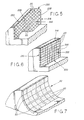
- cutting elements 20 in array 216 are of both shapes, and discontinuities 228 are oriented at an angle to the direction of bit travel. Further, as the array 216 is deeper or higher than that of the previously discussed embodiments, discontinuities 228 are placed at two different angles so as to intersect and further subdivide array 216 into sub-arrays 230. While discontinuities 228 are shown in FIG. 5 to intersect at a substantially right angle, the invention is not so limited, and other intersection angles have equal utility.
- intersecting discontinuities 328 may be utilized in an array 316 so that the array is divided horizontally and vertically instead of at oblique angles as in array 216.
- discontinuities are shown as interruptions in the array of cutting elements 20 which are filled with matrix material.
- the sub-array-offset type discontinuities depicted in FIG. 4 may be utilized in lieu of, or even in addition to, the sub-array-interruption type of discontinuity.
- discontinuities should be placed at no more than substantially one inch intervals in any one direction on the cutting face of the array to prevent accumulation of large residual thermally-induced stresses which could augment impact stresses encountered during drilling to promote bit failure.
- the existence of the discontinuities will preclude the delamination and failure of the sub-array from spreading to adjacent sub-arrays.
- planar encompasses not only both an array on a single plane and adjacent but offset perfectly planar arrays, but also arrays, such as is depicted in FIG. 7 of the drawings, wherein cutting elements 20 define an arcuate cutting surface 22.
- the advantage of such an arcuate surface is to provide additional bonding capability between the bit matrix and the elements 20 by allowing the matrix material as at 50 to extend between adjacent elements 20. This provides not only more opportunity for a strong metallurgical bond if the elements are metal coated as is known in the art, but also lends mechanical support.
- the drill bit and cutting array of the present invention has been described in terms of preferred embodiments, it will be understood that it is not so limited. Those of ordinary skill in the art will appreciate that many additions, deletions and modifications to the preferred embodiments may be made without departing from the spirit and scope of the claimed invention.
- the cutting array of the present invention may be employed with a steel body bit, the array being pre-formed by hot pressing or infiltration techniques known in the art. The preform is then post-brazed or otherwise secured to the bit after the array is furnaced.
- the cutting array might be formed on or bonded to a support including one or more studs which are inserted in apertures on the face of the bit, which technique also facilitates replacement of worn or damaged cutting arrays, or tailoring cutting element compositions to particular formations.
Landscapes
- Engineering & Computer Science (AREA)
- Life Sciences & Earth Sciences (AREA)
- Geology (AREA)
- Mining & Mineral Resources (AREA)
- Mechanical Engineering (AREA)
- Physics & Mathematics (AREA)
- Environmental & Geological Engineering (AREA)
- Fluid Mechanics (AREA)
- General Life Sciences & Earth Sciences (AREA)
- Geochemistry & Mineralogy (AREA)
- Earth Drilling (AREA)
Applications Claiming Priority (2)
| Application Number | Priority Date | Filing Date | Title |
|---|---|---|---|
| US49004190A | 1990-03-06 | 1990-03-06 | |
| US490041 | 1995-06-13 |
Publications (2)
| Publication Number | Publication Date |
|---|---|
| EP0446765A1 true EP0446765A1 (fr) | 1991-09-18 |
| EP0446765B1 EP0446765B1 (fr) | 1995-04-26 |
Family
ID=23946370
Family Applications (1)
| Application Number | Title | Priority Date | Filing Date |
|---|---|---|---|
| EP91103334A Expired - Lifetime EP0446765B1 (fr) | 1990-03-06 | 1991-03-05 | Rangée découpe avec discontinuités pour trépan de forage |
Country Status (5)
| Country | Link |
|---|---|
| EP (1) | EP0446765B1 (fr) |
| AU (1) | AU640749B2 (fr) |
| CA (1) | CA2037480A1 (fr) |
| DE (1) | DE69109160T2 (fr) |
| NO (1) | NO910866L (fr) |
Cited By (11)
| Publication number | Priority date | Publication date | Assignee | Title |
|---|---|---|---|---|
| GB2397836A (en) * | 2003-01-31 | 2004-08-04 | Smith International | Cutter element with multiple cutting lobes |
| US6929079B2 (en) | 2003-02-21 | 2005-08-16 | Smith International, Inc. | Drill bit cutter element having multiple cusps |
| US7631709B2 (en) | 2007-01-03 | 2009-12-15 | Smith International, Inc. | Drill bit and cutter element having chisel crest with protruding pilot portion |
| US7686106B2 (en) | 2007-01-03 | 2010-03-30 | Smith International, Inc. | Rock bit and inserts with wear relief grooves |
| US7690442B2 (en) | 2005-05-17 | 2010-04-06 | Smith International, Inc. | Drill bit and cutting inserts for hard/abrasive formations |
| US7757789B2 (en) | 2005-06-21 | 2010-07-20 | Smith International, Inc. | Drill bit and insert having bladed interface between substrate and coating |
| US7798258B2 (en) | 2007-01-03 | 2010-09-21 | Smith International, Inc. | Drill bit with cutter element having crossing chisel crests |
| US8205692B2 (en) | 2007-01-03 | 2012-06-26 | Smith International, Inc. | Rock bit and inserts with a chisel crest having a broadened region |
| US8607899B2 (en) | 2011-02-18 | 2013-12-17 | National Oilwell Varco, L.P. | Rock bit and cutter teeth geometries |
| EP3117065A4 (fr) * | 2014-03-11 | 2017-12-27 | Varel International, Ind., L.P. | Trépans à matrice courte et méthodologies de fabrication de trépans à matrice courte |
| US11828108B2 (en) | 2016-01-13 | 2023-11-28 | Schlumberger Technology Corporation | Angled chisel insert |
Families Citing this family (2)
| Publication number | Priority date | Publication date | Assignee | Title |
|---|---|---|---|---|
| US7743855B2 (en) | 2006-09-05 | 2010-06-29 | Smith International, Inc. | Drill bit with cutter element having multifaceted, slanted top cutting surface |
| US20140183798A1 (en) | 2012-12-28 | 2014-07-03 | Smith International, Inc. | Manufacture of cutting elements having lobes |
Citations (1)
| Publication number | Priority date | Publication date | Assignee | Title |
|---|---|---|---|---|
| EP0233851A1 (fr) * | 1986-02-19 | 1987-08-26 | Strata Bit Corporation | Elément de coupe comprenant un matériau composite brasé sur un boulon |
-
1991
- 1991-03-04 CA CA002037480A patent/CA2037480A1/fr not_active Abandoned
- 1991-03-05 AU AU72617/91A patent/AU640749B2/en not_active Expired - Fee Related
- 1991-03-05 DE DE69109160T patent/DE69109160T2/de not_active Expired - Fee Related
- 1991-03-05 NO NO91910866A patent/NO910866L/no unknown
- 1991-03-05 EP EP91103334A patent/EP0446765B1/fr not_active Expired - Lifetime
Patent Citations (1)
| Publication number | Priority date | Publication date | Assignee | Title |
|---|---|---|---|---|
| EP0233851A1 (fr) * | 1986-02-19 | 1987-08-26 | Strata Bit Corporation | Elément de coupe comprenant un matériau composite brasé sur un boulon |
Cited By (15)
| Publication number | Priority date | Publication date | Assignee | Title |
|---|---|---|---|---|
| US6883624B2 (en) | 2003-01-31 | 2005-04-26 | Smith International, Inc. | Multi-lobed cutter element for drill bit |
| GB2397836B (en) * | 2003-01-31 | 2006-01-11 | Smith International | Cutter element and drill bit |
| US7086489B2 (en) | 2003-01-31 | 2006-08-08 | Smith International, Inc. | Multi-lobed cutter element for drill bit |
| GB2397836A (en) * | 2003-01-31 | 2004-08-04 | Smith International | Cutter element with multiple cutting lobes |
| US6929079B2 (en) | 2003-02-21 | 2005-08-16 | Smith International, Inc. | Drill bit cutter element having multiple cusps |
| US7690442B2 (en) | 2005-05-17 | 2010-04-06 | Smith International, Inc. | Drill bit and cutting inserts for hard/abrasive formations |
| US7757789B2 (en) | 2005-06-21 | 2010-07-20 | Smith International, Inc. | Drill bit and insert having bladed interface between substrate and coating |
| US7686106B2 (en) | 2007-01-03 | 2010-03-30 | Smith International, Inc. | Rock bit and inserts with wear relief grooves |
| US7631709B2 (en) | 2007-01-03 | 2009-12-15 | Smith International, Inc. | Drill bit and cutter element having chisel crest with protruding pilot portion |
| US7798258B2 (en) | 2007-01-03 | 2010-09-21 | Smith International, Inc. | Drill bit with cutter element having crossing chisel crests |
| US8205692B2 (en) | 2007-01-03 | 2012-06-26 | Smith International, Inc. | Rock bit and inserts with a chisel crest having a broadened region |
| US8607899B2 (en) | 2011-02-18 | 2013-12-17 | National Oilwell Varco, L.P. | Rock bit and cutter teeth geometries |
| US9328562B2 (en) | 2011-02-18 | 2016-05-03 | National Oilwell Varco, L.P. | Rock bit and cutter teeth geometries |
| EP3117065A4 (fr) * | 2014-03-11 | 2017-12-27 | Varel International, Ind., L.P. | Trépans à matrice courte et méthodologies de fabrication de trépans à matrice courte |
| US11828108B2 (en) | 2016-01-13 | 2023-11-28 | Schlumberger Technology Corporation | Angled chisel insert |
Also Published As
| Publication number | Publication date |
|---|---|
| DE69109160T2 (de) | 1995-08-31 |
| AU640749B2 (en) | 1993-09-02 |
| AU7261791A (en) | 1991-09-12 |
| NO910866L (no) | 1991-09-09 |
| EP0446765B1 (fr) | 1995-04-26 |
| CA2037480A1 (fr) | 1991-09-07 |
| NO910866D0 (no) | 1991-03-05 |
| DE69109160D1 (de) | 1995-06-01 |
Similar Documents
| Publication | Publication Date | Title |
|---|---|---|
| US5147001A (en) | Drill bit cutting array having discontinuities therein | |
| US4889017A (en) | Rotary drill bit for use in drilling holes in subsurface earth formations | |
| US7407012B2 (en) | Thermally stable diamond cutting elements in roller cone drill bits | |
| EP0718462B1 (fr) | Elément coupant pour trépan de forage et procédé de montage d'un élément coupant sur un trépan de forage | |
| US6725953B2 (en) | Drill bit having diamond impregnated inserts primary cutting structure | |
| EP0828917B1 (fr) | Structures de coupe essentiellement en diamant destinees aux forages | |
| US4991670A (en) | Rotary drill bit for use in drilling holes in subsurface earth formations | |
| US7757785B2 (en) | Modified cutters and a method of drilling with modified cutters | |
| CA2505828C (fr) | Dispositifs de coupe modifies | |
| EP2464810B1 (fr) | Procédés de formation d'éléments de coupe en diamant polycristallin, éléments de coupe et outils de forage portant des éléments de coupe | |
| CA2671061C (fr) | Trepan de carottage avec hauteur de matrice etendue | |
| US7740090B2 (en) | Stress relief feature on PDC cutter | |
| EP0246789A2 (fr) | Elément de coupe pour un trépan rotatif, trépan rotatif avec un tel élément, et procédé de fabrication de cet élément | |
| EP0144222B1 (fr) | Trépan de forage rotatif | |
| EP0853184A2 (fr) | Elément de coupe extra-dure avec rigidité et capacité de transfert de chaleur et efficacité de coupe accrues | |
| EP0822318A1 (fr) | Perfectionnements aux trépans de forage rotatifs | |
| EP0446765B1 (fr) | Rangée découpe avec discontinuités pour trépan de forage | |
| BR112012027627A2 (pt) | compactos de diamante policristalino, elementos cortantes e ferramentas de perfuração do solo incluindo esses compactos e métodos de formação desses compactos e ferramentas de perfuração do solo | |
| US7469757B2 (en) | Drill bit with diamond impregnated cutter element | |
| EP0155026A2 (fr) | Trépan de forage rotatif avec éléments de coupe comportant une fine couche abrasive | |
| CA2584928C (fr) | Trepan comprenant une structure de coupe principale avec pieces rapportees impregnees de diamant |
Legal Events
| Date | Code | Title | Description |
|---|---|---|---|
| PUAI | Public reference made under article 153(3) epc to a published international application that has entered the european phase |
Free format text: ORIGINAL CODE: 0009012 |
|
| AK | Designated contracting states |
Kind code of ref document: A1 Designated state(s): BE DE FR GB NL |
|
| 17P | Request for examination filed |
Effective date: 19920318 |
|
| 17Q | First examination report despatched |
Effective date: 19930421 |
|
| GRAA | (expected) grant |
Free format text: ORIGINAL CODE: 0009210 |
|
| AK | Designated contracting states |
Kind code of ref document: B1 Designated state(s): BE DE FR GB NL |
|
| REF | Corresponds to: |
Ref document number: 69109160 Country of ref document: DE Date of ref document: 19950601 |
|
| ET | Fr: translation filed | ||
| PLBE | No opposition filed within time limit |
Free format text: ORIGINAL CODE: 0009261 |
|
| STAA | Information on the status of an ep patent application or granted ep patent |
Free format text: STATUS: NO OPPOSITION FILED WITHIN TIME LIMIT |
|
| 26N | No opposition filed | ||
| PGFP | Annual fee paid to national office [announced via postgrant information from national office to epo] |
Ref country code: FR Payment date: 19970213 Year of fee payment: 7 |
|
| PGFP | Annual fee paid to national office [announced via postgrant information from national office to epo] |
Ref country code: NL Payment date: 19970218 Year of fee payment: 7 |
|
| PG25 | Lapsed in a contracting state [announced via postgrant information from national office to epo] |
Ref country code: FR Free format text: THE PATENT HAS BEEN ANNULLED BY A DECISION OF A NATIONAL AUTHORITY Effective date: 19980331 |
|
| PG25 | Lapsed in a contracting state [announced via postgrant information from national office to epo] |
Ref country code: NL Free format text: LAPSE BECAUSE OF NON-PAYMENT OF DUE FEES Effective date: 19981001 |
|
| NLV4 | Nl: lapsed or anulled due to non-payment of the annual fee |
Effective date: 19981001 |
|
| REG | Reference to a national code |
Ref country code: FR Ref legal event code: ST |
|
| REG | Reference to a national code |
Ref country code: GB Ref legal event code: IF02 |
|
| PGFP | Annual fee paid to national office [announced via postgrant information from national office to epo] |
Ref country code: GB Payment date: 20030226 Year of fee payment: 13 |
|
| PGFP | Annual fee paid to national office [announced via postgrant information from national office to epo] |
Ref country code: BE Payment date: 20030228 Year of fee payment: 13 |
|
| PGFP | Annual fee paid to national office [announced via postgrant information from national office to epo] |
Ref country code: DE Payment date: 20030331 Year of fee payment: 13 |
|
| PG25 | Lapsed in a contracting state [announced via postgrant information from national office to epo] |
Ref country code: GB Free format text: LAPSE BECAUSE OF NON-PAYMENT OF DUE FEES Effective date: 20040305 |
|
| PG25 | Lapsed in a contracting state [announced via postgrant information from national office to epo] |
Ref country code: BE Free format text: LAPSE BECAUSE OF NON-PAYMENT OF DUE FEES Effective date: 20040331 |
|
| BERE | Be: lapsed |
Owner name: *NORTON CY Effective date: 20040331 |
|
| PG25 | Lapsed in a contracting state [announced via postgrant information from national office to epo] |
Ref country code: DE Free format text: LAPSE BECAUSE OF NON-PAYMENT OF DUE FEES Effective date: 20041001 |
|
| GBPC | Gb: european patent ceased through non-payment of renewal fee |