EP0446533A2 - Apparatus and method for detecting inhomogeneities in semi-plastic substances through ultrasound - Google Patents
Apparatus and method for detecting inhomogeneities in semi-plastic substances through ultrasound Download PDFInfo
- Publication number
- EP0446533A2 EP0446533A2 EP19900314450 EP90314450A EP0446533A2 EP 0446533 A2 EP0446533 A2 EP 0446533A2 EP 19900314450 EP19900314450 EP 19900314450 EP 90314450 A EP90314450 A EP 90314450A EP 0446533 A2 EP0446533 A2 EP 0446533A2
- Authority
- EP
- European Patent Office
- Prior art keywords
- substance
- delay material
- probe
- semi
- plastic
- Prior art date
- Legal status (The legal status is an assumption and is not a legal conclusion. Google has not performed a legal analysis and makes no representation as to the accuracy of the status listed.)
- Granted
Links
Images
Classifications
-
- G—PHYSICS
- G01—MEASURING; TESTING
- G01N—INVESTIGATING OR ANALYSING MATERIALS BY DETERMINING THEIR CHEMICAL OR PHYSICAL PROPERTIES
- G01N29/00—Investigating or analysing materials by the use of ultrasonic, sonic or infrasonic waves; Visualisation of the interior of objects by transmitting ultrasonic or sonic waves through the object
- G01N29/02—Analysing fluids
- G01N29/032—Analysing fluids by measuring attenuation of acoustic waves
-
- G—PHYSICS
- G01—MEASURING; TESTING
- G01N—INVESTIGATING OR ANALYSING MATERIALS BY DETERMINING THEIR CHEMICAL OR PHYSICAL PROPERTIES
- G01N29/00—Investigating or analysing materials by the use of ultrasonic, sonic or infrasonic waves; Visualisation of the interior of objects by transmitting ultrasonic or sonic waves through the object
- G01N29/04—Analysing solids
- G01N29/11—Analysing solids by measuring attenuation of acoustic waves
-
- G—PHYSICS
- G10—MUSICAL INSTRUMENTS; ACOUSTICS
- G10K—SOUND-PRODUCING DEVICES; METHODS OR DEVICES FOR PROTECTING AGAINST, OR FOR DAMPING, NOISE OR OTHER ACOUSTIC WAVES IN GENERAL; ACOUSTICS NOT OTHERWISE PROVIDED FOR
- G10K11/00—Methods or devices for transmitting, conducting or directing sound in general; Methods or devices for protecting against, or for damping, noise or other acoustic waves in general
- G10K11/18—Methods or devices for transmitting, conducting or directing sound
- G10K11/26—Sound-focusing or directing, e.g. scanning
- G10K11/32—Sound-focusing or directing, e.g. scanning characterised by the shape of the source
-
- G—PHYSICS
- G01—MEASURING; TESTING
- G01N—INVESTIGATING OR ANALYSING MATERIALS BY DETERMINING THEIR CHEMICAL OR PHYSICAL PROPERTIES
- G01N2291/00—Indexing codes associated with group G01N29/00
- G01N2291/02—Indexing codes associated with the analysed material
- G01N2291/023—Solids
- G01N2291/0231—Composite or layered materials
-
- G—PHYSICS
- G01—MEASURING; TESTING
- G01N—INVESTIGATING OR ANALYSING MATERIALS BY DETERMINING THEIR CHEMICAL OR PHYSICAL PROPERTIES
- G01N2291/00—Indexing codes associated with group G01N29/00
- G01N2291/02—Indexing codes associated with the analysed material
- G01N2291/023—Solids
- G01N2291/0235—Plastics; polymers; soft materials, e.g. rubber
-
- G—PHYSICS
- G01—MEASURING; TESTING
- G01N—INVESTIGATING OR ANALYSING MATERIALS BY DETERMINING THEIR CHEMICAL OR PHYSICAL PROPERTIES
- G01N2291/00—Indexing codes associated with group G01N29/00
- G01N2291/02—Indexing codes associated with the analysed material
- G01N2291/023—Solids
- G01N2291/0238—Wood
-
- G—PHYSICS
- G01—MEASURING; TESTING
- G01N—INVESTIGATING OR ANALYSING MATERIALS BY DETERMINING THEIR CHEMICAL OR PHYSICAL PROPERTIES
- G01N2291/00—Indexing codes associated with group G01N29/00
- G01N2291/04—Wave modes and trajectories
- G01N2291/044—Internal reflections (echoes), e.g. on walls or defects
-
- G—PHYSICS
- G01—MEASURING; TESTING
- G01N—INVESTIGATING OR ANALYSING MATERIALS BY DETERMINING THEIR CHEMICAL OR PHYSICAL PROPERTIES
- G01N2291/00—Indexing codes associated with group G01N29/00
- G01N2291/10—Number of transducers
- G01N2291/101—Number of transducers one transducer
Landscapes
- Physics & Mathematics (AREA)
- Acoustics & Sound (AREA)
- Health & Medical Sciences (AREA)
- Life Sciences & Earth Sciences (AREA)
- Chemical & Material Sciences (AREA)
- Analytical Chemistry (AREA)
- Biochemistry (AREA)
- General Health & Medical Sciences (AREA)
- General Physics & Mathematics (AREA)
- Immunology (AREA)
- Pathology (AREA)
- Engineering & Computer Science (AREA)
- Multimedia (AREA)
- Investigating Or Analyzing Materials By The Use Of Ultrasonic Waves (AREA)
- Extrusion Moulding Of Plastics Or The Like (AREA)
Abstract
Description
- This invention relates to an apparatus and method for detecting inhomogeneities in semi-plastic substances, such as soap bars, through the use of ultrasound.
- Ultrasound has been used in many fields as a non-destructive, non-invasive testing and diagnostic technique. It has been employed industrially for measuring the thickness of machined parts, monitoring corrosion inside pipes and vessels, finding flaws in welds and castings, and in measuring material properties. In medicine, it is used widely as a diagnostic imaging tool for scanning the abdomen, heart and other areas to detect disease or abnormalities.
- A variety of consumer products have been monitored for quality control through ultrasound. For instance, U.S. 4,208,915 (Edwards) discloses a method for determining by ultrasonic frequency detection foreign material in food products. A plurality of transducers are disposed in a rotatable cylinder having a liquid conductor. The cylinder having a surrounding flexible wall is compressed against the top surface of food products being transported beneath the cylinder on a conveyor belt. Food items stated to be suitable for examination are meat patties, fish fillets, boneless chicken products and, especially, hamburgers. Typical foreign objects include metal, bone particles, hair and pieces of cloth.
- Fluid processed foodstuffs can also be inspected ultrasonically as reported in U.S. 4,384,476 (Black et al). Among the foodstuffs amenable to inspection by this technique are flowable pasty or comminuted fruits and vegetables, ketchup, ground meats and soups. Also monitorable are aqueous slurries of fruits and vegetables which may be checked for unremoved pits, seeds, stems or even for rotten cores. The method involves transporting the foodstuff through a pipeline that includes an inspection station formed from a light transparent plastic. A curtain of ultrasonic sound is passed through an entire cross-section of the fluid foodstuff passing through the inspection station. Individual transducers are reported to be of a ceramic solid solution of lead zirconate and lead titanate dimensioned such that they oscillate and may be driven at a frequency of approximately 2.25 MHz.
- U.S. 4,821,573 quality tests food filled packages subject to spoilage. The inspection method involves shaking each package in an agitation device and downstrem therefrom passing the package between a package body thickness limiter immersed in a water tank wherethrough the ultrasound is transmitted. The useful wavelength region is stated to be between 0.5 and 20 MHz.
- In the Journal of the American Oil Chemists' Society, 1984, 61(3) 560-564, there has been reported the use of ultrasound to investigate solid fat index dilatation during solidification of oils and fats. A doctoral dissertation has even been written about the technique as it relates to cheese wheys, margarines, and frozen dessert mixes. See Dissertation Abstracts International, B 1972, 33(4) 1604-1605.
- Beyond foods, ultrasound has been employed to investigate solids levels in mouthwashes (J. Pharm. Sci., 67(4), 492-6 (1978)) as well as with cosmetic creams (Izv. Vyssh. Uchebn. Zaved., Pishch. Tekhnol., (5), 34-7 (1988)).
- Most of the foregoing art has focused upon substrates that are either solids or substantially liquids. The probe of these type materials is a reasonably straight-forward task. Detectors can readily make contact and these materials echo easily interpretable signals. On the other hand, semi-plastic substances are not easily amenable to being probed. Difficulties in contact between probe and substance as well as interpretation of signals arises in this area.
- The present invention seeks to provide an apparatus and method for detecting inhomogeneities within a semi-plastic substance. Examples of imhomogeneities are foreign materials, undesirable phase structures, crystallinity and excess moisture in semi-plastic substances through the use of ultrasound. A more specific application of this invention is to detect metal, glass, wood or other such foreign objects in toilet bars containing soap.
- A method for detecting inhomogeneities in a semi-plastic substance is herewith provided, through steps comprising:
generating an ultrasonic wave and emitting the wave through an ultrasonic probe, the probe including an ultrasound delay material at one end thereof, the delay material being in solid form;
contacting the delay material against the substance;
directing the wave from the probe through the delay material and then through the substance;
receiving a signal based on a return of the wave passing through the substance; and
analyzing the signal by comparing the signal to a reference value. - The above described method is particularly suited to the detection of foreign material such as pieces of metal, glass, paper, wood and the like in a toilet bar containing soap. Other inhomogeneities may also be monitored including proper phase structure, moisture content and crystallinity. The invention may be utilised for quality control and/or process regulation.
- In a preferred arrangement the substance is extruded to provide a continuous flow of the substance and the delay material is placed in contact with the continuous flow of the substance. This can be done intermediately between extrusion of the substance into a flowing stream and cutting the extruded flow into separate pieces.
- It may prove convenient to place the ultrasonic probe at the orifice region of the extruder. Notably it may be fitted to a housing through which the extruded material flows, with a surface of the delay material flush with the housing, to contact the flowing substance.
- Analysis of the received signal may be carried out by means of a computer program acting to compare the signal with a reference value.
- It is particularly envisaged that the semi-plastic substance will be an extrudable detergent composition, for instance a composition intended for processing into toilet bars for personal washing. Such composition will generally contain at least 5%, better at least 50% by weight of surfactant.
- The semi-plastic substance may well be liquifiable at temperatures below 150°C.
- Consumer toilet bars are the most conspicuous commercial example of semi-plastic material within the context of this invention. Most toilet bars contain a semi-solid surfactant, most often that of soap. Other surfactants may also be employed exclusively or in combination with soap. These substances include fatty acyl isethionate, fatty alkyl glycerol ether sulfonate, fatty alcohol sulfate, alpha-olefin sulfonate, acyl taurate, mono-and di-alkyl phosphate, dialkylamide oxide, alkyl sulfosuccinate, fatty acid or amido betaine, sulfobetaine, alkane sulfonate and mixtures thereof. Most preferably, soap will be present and in an amount of at least 5% by weight.
- Several types of flaws or foreign objects may be detected in the substance by the method of this invention. For not always well explained reasons, manufacture of semi-plastic substances such as toilet bars occasionally inadvertently includes undesirable foreign objects like small pieces of glass, wood chips, cardboard or metal. Bars with these contaminants must be apprehended before shipment to the consumer.
- The apparatus and method of this invention may also be applied to the measurement of moisture content or phase structure in toilet bars. Phases may be that of the delta, kappa, gamma or zeta phases each of which is desirably controlled to obtain the desired performance properties. Crystallization within the substance may also lead to the undesired formation of sandy particles (known as "sand") for which ultrasound may serve as a useful probe. Transparency of milled soap may also be monitored by this method, phase structure and crystallization being significant factors in achieving transparency.
- In a second aspect this invention provides apparatus for detecting inhomogeneities in a semi-plastic substance, the apparatus comprising:
an ultrasonic probe including an ultrasound delay material in solid form positioned to contact the semi-plastic substance; and
means for analyzing a return signal that was directed by the probe and has passed through the semi-plastic substance, the analysis including comparison of the return signal to a reference value. - The apparatus may include an extruder for extruding (and possibly also mixing) the semi-plastic substance, with the ultrasonic probe positioned to contact the substance downstream of the extruder, especially at an orifice region thereof.
- An embodiment of this invention will next be described with reference to the drawings wherein:
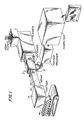
Fig. 1 schematically illustrates an embodiment of the overall apparatus including extruder, ultrasonic probe and cutter;
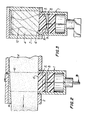
Fig. 2 is a cross section of the extruder-probe area taken along line 2-2 of Fig. 1; and
Fig. 3 is a cross section of the extruder-probe area taken along line 3-3 of Fig. 2. - An ultrasonic probe 1 is positioned at an
exit 2 of anextruder 3. The extruder receives material from a soap plodder (itself a form of extruder) connected to the upstream end of theextruder 3. Assemi-plastic product 4 emerges through theexit 2 of the extruder, the probe through an end fitted with asolid delay material 5 contacts anouter surface 6 of the extruded substance. Fig. 1 illustrates the overall apparatus. Of particular advantage in sensing at theextruder exit 2 is that this avoids sensing of full vat of substance in gross which would contain both satisfactory as well as, perhaps, unsatisfactory fractions. On the other hand, the chosen point of sensing avoids evaluating the substance after it has been formed into small articles, e.g. separate toilet bars. Thus, the ultrasonic inspection is carried out at an advantageous point in the process, namely a point subsequent to formulation of the semi-plastic but prior to its breakup, e.g. through a cutter 7, into individual semi-plastic articles. - Before further details are delineated, a general overview of ultrasound principles would assist in understanding the invention. A key element of the ultrasound probe is a transducer. A pulser unit supplies necessary high voltage electrical energy to excite a surface of the transducer. Mechanical oscillations resulting therefrom are transmitted into the test material, i.e. the semi-plastic substance, via a suitable coupling agent. Returning sound waves are then processed by a receiver. These waves may be displayed on an oscilloscope in the form of amplitude versus time (A-Scan). This pulse-echo technique is capable of detecting impurities which cause a sufficient "discontinuity" in the test material structure.
- Discontinuities occur at interfaces where there is a sudden change in the acoustic properties of the test material. If a plain sound wave front strikes an interface between two different media, a portion of the wave is reflected with remaining energy passing through the interface. The ratio of the sound pressure of the reflective wave versus the transmitted wave depends primarily on the acoustic impedance, Z (Z = density of material x speed of sound in material), of the adjoining materials, and the surface structure and size of the reflector. Particles with a characteristic speed of sound or density much different from that of the test material, e.g. soap versus steel, will produce strong echo returns and thus will be easier to detect.
- The relative effectiveness of transducers in detecting impurities depends on many factors. These include the geometry of the transducer, operating frequency, material construction, pulser, and receiver. The sound pressure distribution in space of ultrasonic units is a direct consequence of its material composition and geometry of the probe under consideration. Theoretical analysis indicates variously shaped probes share common characteristics in their energy distribution.
- High frequency sound waves exhibit high directionality with the most significant portion of the sound field concentrated in a sector known as the sound beam. In a region immediately in front of the transducer crystal there is an area with strong sound pressure variations, including null energy spots, referred to as the near zone (Fresnel zone). Attempts to detect inclusions within the near zone can lead to unreliable results and thus the working range of the probe should be designed to eliminate or avoid this zone. An estimate for the near field of circular transducers can be determined from the following equation:

where:
d = transducer diameter
lambda = wave length
f = frequency
c = local speed of sound - Smaller diameter crystals, lower operating frequencies and materials with a fast local speed of sound will produce shorter near field lengths. The near field inhomogeneity of a rectangular transducer is less marked than that of a circular transducer of similar size. As a rough guide, the near field of a rectangular transducer extends for a distance somewhat beyond that of a circular transducer of diameter equal to the maximum length of the rectangle. Constructive interference of plane sound waves creates regions of high pressure within the near field. The point of the last axial maximum defines the transition between the near zone and far zone (Fraunhofer zone). The near field decreases from an approximate diameter of that of the crystal to about half that size at the end of the near field. At this point the sound beam is concentrated to its greatest extent.
- In the far field the sound beam begins to diverge with an approximate half angle, gama of:
gama = divergence angle
for disc oscillators:
gama (6 dB down) = arc sin (.51 * lambda)/d
gama (20 dB down) = arc sin (.87 * lambda)/d
for rectangular oscillators:
gama (6 dB down) = arc sin (.44 * lambda)/s
gama (20 dB down) = arc sin (.74 * lambda)/s
where:
lambda = wave length
d = diameter of crystal
s = side of the rectangular oscillator
- In general for unfocused transducers, larger diameter crystals with high operating frequencies produce more coherent sound beams. For all crystals, regardless of shape, the far field pressure amplitude decreases with distance due to the divergence of the beam. In addition, the material structure absorbs some of the acoustic energy, converting sound into heat.
- This combined with losses induced from scattering at microscopic interfaces is referred to as sound attenuation. Energy decays in an exponential manner in relation to distance:

where: - p(z)
- = pressure at distance z from transducer face
- po
- = originating pressure
- alpha
- = attenuation coefficient (for a given material this value varies depending on frequency of oscillator)
- z
- = distance from transducer surface
- Total decrease in sound energy is an accumulation of distance losses and attenuation.
- We have determined from our studies that, in general, probes with higher echo returns suffer from a resolution problem with semi-plastic substances in the frontal portion of the signal. This effect leads to unacceptable near surface detection of particles. Attempts to decrease these initial main bang oscillations with a built-in receiver damping circuit was found to produce a large decrease in overall signal strength, indicating that transducers with high damping would result in probes with poor particle detection properties.
- In this invention, the problem has now been solved by employing a
delay material 5 for interfacing between thesubstance 4 to be tested and thetransducer 8 of the probe 1. Thisdelay material 5 provides sufficient damping to reduce frontal oscillations but insufficient to attenuate the entire signal. A cleaner and dramatic increase in surface particle detection has been achieved. Fig. 2 and 3 schematically illustrate the probe with its components. - Selection of the
delay material 5 depends on several factors. If the probe is applied close to the orifice of the extruder, the delay material composition should withstand high temperatures (above about 60°X), humidity and caustic chemicals involved in extruding semi-plastics such as soap. A material with a high local speed of sound was found desirable to reduce the near field length. Also desirable was for the material to have an acoustic impedance close to that of the semi-plastic substance to allow for more efficient transmission of sound energy into that substance. - Based upon the aforementioned considerations, the best delay material was in the form of a solid with an impedance ranging from 0.20 to 1.0, preferably from about 0.25 to about 0.50, optimally between 0.28 and 0.45 (gm/cm²-sec) x 10⁶.
- Under conditions where the extruder exit is heated and the probe is close to that exit, it is important that the delay material have sufficiently high melting point and that it have good abrasion resistance.
- Several plastic materials were found to meet the criterion necessary for an effective delay. Particularly preferred are thermoplastic polymers, examples of which include polyamides (nylon), polyethylene terephthalate, polycarbonate (Lexan, ex General Electric), polyacetal (Delrin, ex Dupont), polyphenylene oxide, polysulfone and formaldehyde melamine resins (Bakelite).
- The
transducer 8 is preferably formed from a ceramic. This material allows the transducer to withstand elevated temperatures and also to resist abrasion. - Geometry of both the transducer and delay material is important. Advantageously, an end 9 of the transducer in contact with the
delay material 5 should have an outwardly concave curvature. Extent of curvature for the transducer end surface should be in an amount sufficient to focus abeam 12 near the centre of the semi-plastic object being measured. The delay material should exhibit a complementaryconvex bulge 10 to directly contact the curved transducer. - Any geometry may usefully be employed as a lower surface of the delay material which contacts the substance to be tested. For these purposes, a round flat lower contact surface has been found to be quite suitable.
- A still further advantageous structural feature is that the
transducer 8 should be in the form of a rectangular elongate bar. The rectangular elongate geometry was found desirable to provide adequate ultrasound contact with the extruded substance that continuously moves outward from the extruder exit. Ratio of length to width of the transducer should range from about 5:1 to about 1.2:1, preferably between about 2:1 to 1.75:1. - All of the foregoing transducer structural features have been formulated with the objective of providing a focused sharp knife-edge line of energy. This focused beam provides a very good return signal to monitor in contrast to signals generated from a dispersed entry beam having weak force.
- The mounting system for the transducer is designed to be bolted directly to the extruder head. This system must be capable of keeping the transducer in direct contact with the semi-plastic surface, so ensuring good signal return. With respect to soap substances it has been found that a contact pressure of from about 10 to 50 pounds per square inch (6.9 x 10⁴ to 3.4 x 10⁵ Pascal) optimally about 30 pounds per square inch (2.1 x 10⁵ Pascal) is sufficient to ensure the required signal levels.
- An advantageous feature which allows the desired contact pressure is the employment of a
wedge 14 in the exit orifice channel. Advantageously, the wedge may be integral with a wall of the exit orifice channel opposite to that of the delay material. The wedge should be so angled that it causes the extruded substance to be compressed as it passes downstream past the delay contact lower surface. A suitable wedging angle is from about 1° to about 10°, preferably between 1° and 4°. This wedging action ensures tight contact between the substance and the delay material. Tight contact ensures sharper imaging of the ultrasonic wave. - Resonating frequencies of the transducer may also be important in achieving optimum results. Frequencies between about 1 and 4 or 5 MHz, preferably between 1.0 and 2.25 MHz, provide satisfactory results.
- Operation of the transducer will normally require the input of anywhere from 100 to 1,000 volt, preferably 200-500 volt, impulse to resonate the test substance.
- We have obtained best performance of the pulser unit at a 300 volt signal delivery for a duration of at least 1/2 a wavelength. A suitable pulser is available from Harisonic Laboratories, Division of Stavely Sensors, Model MP127, and receiver unit Model MR106 which combination provides extremely good results because of the high power output and adjustment flexibility.
- The following examples will more fully illustrate the embodiments of this invention. All parts, percentages and proportions referred to herein and in the appended claims are by weight of the total composition unless otherwise stated.
- A toilet bar composition was prepared having the formulation appearing in Table I.

- The components of Table I were blended together at a temperature of 110°C with water being permitted to evaporate from the reactor. At the end of the reaction, the batch was discharged onto a chill roll at 38°C. The chill rolled chips were then milled. Milled material was then refined and then extruded into logs through a 15cm (6 inch) refiner/plodder. Temperatures varied between 35°C and 44°C in the plodder with plodding times of from 12 to 20 minutes.
- At the exit of the plodder was placed an ultrasound probe whose transducer had dimensions of 19mm width x 35mm length formed of ceramic material with curvature as illustrated in Fig. 3. Operating frequency was at 1.0 megahertz. The extruder exit wall opposite the thermoplastic delay material was angled to achieve a decreasing soap wedge of 1°-4° angle.
- Excellent detection was achieved for glass, wood chips and metal particles which were deliberately added to the batch prior to extrusion.
- Subsequent to the ultrasound detection, the continuous log exiting the extruder was cut into toilet bar billets and removed by conveyor belt. Thereafter the billets were stamped with a logo.
- In the context of the previous Example, herein is reported the effect of various resonating frequencies on the quality of the analysis. Table II provides this comparison.

- The procedure of Example 1 was repeated, substituting a circular transducer for the rectangular transducer used in Example 1.
- Table III shows the signal quality with the two kinds of transducer.

Claims (11)
- A method for detecting inhomogeneities in a semi-plastic substance through steps comprising:(a) generating an ultrasonic wave and emitting said wave outwardly through an ultrasonic probe, said probe including an ultrasound delay material at one end thereof, said delay material being in solid form;(b) contacting said delay material against a face of said substance;(c) directing said wave from said probe through said delay material and then through said substance;(d) receiving a signal based on a return of said wave passing through said substance; and(e) analyzing said signal by comparing said signal to a reference value.
- A method according to claim 1 comprising extruding a continuous flow of said substance and contacting said delay material with the flow of said substance.
- A method according to claim 1 or claim 2 wherein the substance is a detergent composition containing surfactant.
- A method according to claim 3 wherein the composition includes at least 5% soap.
- A method according to any one of the preceding claims wherein said extruded substance as it flows downstream past said delay material is subjected to a reducing flow cross section to achieve good contact between said substance and said material.
- An apparatus for detecting inhomogeneities in a semi-plastic substance, the apparatus comprising:(a) an ultrasonic probe said probe including an ultrasound delay material in solid form positioned to contact said semi-plastic substance; and(b) means for analyzing a return signal that was directed by said probe and has passed through said semi-plastic substance, said analysis including comparison of said return signal to a reference value.
- Apparatus according to claim 6 also comprising an extruder for extruding a continuous flow of the semi-plastic substance, with the ultrasonic probe positioned to contact the flow of substance downstream of the extruder.
- An apparatus according to claim 6 or claim 7 wherein said ultrasonic probe is formed from a ceramic.
- An apparatus according to claim 6, claim 7 or claim 8 wherein said delay material is formed from a thermoplastic.
- An apparatus according to any one of claims 6 to 9 wherein said probe includes a transducer with a lower surface in contact with the delay material, which surface has a concave structure.
- An apparatus according to any one of claims 6 to 10 wherein a channel containing said flow as it passes said delay material is formed with a decreasing flow cross section for urging said semi-plastic substance towards said delay material to achieve good contact between said substance and said delay material.
Applications Claiming Priority (2)
| Application Number | Priority Date | Filing Date | Title |
|---|---|---|---|
| US461200 | 1990-01-05 | ||
| US07/461,200 US5062299A (en) | 1990-01-05 | 1990-01-05 | Apparatus and method for detecting inhomogeneities in semi-plastic substances through ultrasound |
Publications (3)
| Publication Number | Publication Date |
|---|---|
| EP0446533A2 true EP0446533A2 (en) | 1991-09-18 |
| EP0446533A3 EP0446533A3 (en) | 1991-11-27 |
| EP0446533B1 EP0446533B1 (en) | 1997-04-09 |
Family
ID=23831605
Family Applications (1)
| Application Number | Title | Priority Date | Filing Date |
|---|---|---|---|
| EP90314450A Expired - Lifetime EP0446533B1 (en) | 1990-01-05 | 1990-12-31 | Apparatus and method for detecting inhomogeneities in semi-plastic substances through ultrasound |
Country Status (5)
| Country | Link |
|---|---|
| US (1) | US5062299A (en) |
| EP (1) | EP0446533B1 (en) |
| CA (1) | CA2033533C (en) |
| DE (1) | DE69030436T2 (en) |
| ES (1) | ES2099090T3 (en) |
Cited By (1)
| Publication number | Priority date | Publication date | Assignee | Title |
|---|---|---|---|---|
| ES2130095A1 (en) * | 1997-11-27 | 1999-06-16 | Gres De Nules S A Gresnul S A | Process and device for measuring and monitoring the apparent density and other characteristics of ceramic pieces |
Families Citing this family (12)
| Publication number | Priority date | Publication date | Assignee | Title |
|---|---|---|---|---|
| DE4203755C2 (en) * | 1992-02-10 | 1995-04-20 | Reifenhaeuser Masch | Process for regulating the individual layer thicknesses of a co-extruded multilayer plastic web |
| US5606113A (en) * | 1994-09-06 | 1997-02-25 | The University Of Chicago | Acoustic methods to monitor sliver linear density and yarn strength |
| FI990153A0 (en) * | 1999-01-28 | 1999-01-28 | Valtion Teknillinen | On-line moisture measurement method for material with homogeneous density distribution / wood chips based on transmission of gamma radiation and measurement of material thickness |
| US6992771B2 (en) * | 2001-11-28 | 2006-01-31 | Battelle Memorial Institute | Systems and techniques for detecting the presence of foreign material |
| US6786096B2 (en) | 2001-11-28 | 2004-09-07 | Battelle Memorial Institute | System and technique for detecting the presence of foreign material |
| US6763698B2 (en) | 2002-03-15 | 2004-07-20 | Battelle Memorial Institute | Self calibrating system and technique for ultrasonic determination of fluid properties |
| US7395711B2 (en) * | 2002-05-06 | 2008-07-08 | Battelle Memorial Institute | System and technique for characterizing fluids using ultrasonic diffraction grating spectroscopy |
| US20060266119A1 (en) * | 2005-05-23 | 2006-11-30 | Applied Sonics, Incorporated | Ultrasonic system for on-line monitoring of pressed materials |
| US7712651B2 (en) * | 2008-01-04 | 2010-05-11 | G. James Australia Pty. Ltd. | Method of welding heated log segments in an aluminum extrusion process |
| US8181523B2 (en) * | 2008-07-22 | 2012-05-22 | Nuovo Pignone S.P.A. | Ultrasound inspection methods for noisy cast materials and related probes |
| CA2811760C (en) * | 2010-09-21 | 2018-08-28 | Nimtech Inc. | Method and system for product supply chain assurance |
| EP2551087A1 (en) * | 2011-07-28 | 2013-01-30 | Rhein Chemie Rheinau GmbH | Method for determining the quality of unlinked rubber mixtures and corresponding device |
Citations (4)
| Publication number | Priority date | Publication date | Assignee | Title |
|---|---|---|---|---|
| US2966056A (en) * | 1956-01-20 | 1960-12-27 | Curtiss Wright Corp | Ultrasonic testing device |
| GB1370946A (en) * | 1971-05-14 | 1974-10-16 | Wavin Plastics Ltd | Extrusion of thermoplastics materials |
| US4208915A (en) * | 1979-01-31 | 1980-06-24 | Edwards Bill R | Method of determining foreign material in food products using ultrasonic sound |
| US4384476A (en) * | 1980-12-11 | 1983-05-24 | Metramatic Corp. | Apparatus for and method of ultrasonically inspecting foodstuffs |
Family Cites Families (9)
| Publication number | Priority date | Publication date | Assignee | Title |
|---|---|---|---|---|
| GB998173A (en) * | 1963-02-04 | 1965-07-14 | George Andrew Douglas Gordon | Method and apparatus for destroying limited groups of cells |
| US3832887A (en) * | 1969-06-25 | 1974-09-03 | Automation Ind Inc | Ultrasonic inspection apparatus |
| DE2345884C3 (en) * | 1973-09-12 | 1979-05-23 | Ruhrkohle Ag, 4300 Essen | Procedure and arrangement for apron exploration in the course of mining a coal seam |
| JPS5550438B2 (en) * | 1974-11-25 | 1980-12-18 | ||
| US4509360A (en) * | 1983-06-24 | 1985-04-09 | Massachusetts Institute Of Technology | On-line measurement of fluid mixtures |
| FI71018C (en) * | 1983-07-06 | 1986-10-27 | Valmet Oy | FOERFARANDE BASERANDE SIG PAO EKOLODNING MED ULTRALJUD FOER AT FOELJA MED BANBILDNINGEN OCH / ELLER MASSASUSPENSIONSSTROE MMN PAO EN VIRADEL OCH / ELLER I EN INLOPPSLAODA I EN PAPPERS MAKIN OCH ANORDNING FOER TIL |
| DE3604111A1 (en) * | 1986-02-10 | 1987-10-15 | Nukem Gmbh | METHOD AND DEVICE FOR DETECTING DEFECTS IN AN OBJECT |
| US4821573A (en) * | 1986-10-15 | 1989-04-18 | Fujimori Kogyo Co., Ltd. | Ultrasonic method of inspecting contents of a package and apparatus thereof |
| US4821558A (en) * | 1987-05-01 | 1989-04-18 | Abbott Laboratories | Ultrasonic detector |
-
1990
- 1990-01-05 US US07/461,200 patent/US5062299A/en not_active Expired - Fee Related
- 1990-12-31 EP EP90314450A patent/EP0446533B1/en not_active Expired - Lifetime
- 1990-12-31 DE DE69030436T patent/DE69030436T2/en not_active Expired - Fee Related
- 1990-12-31 ES ES90314450T patent/ES2099090T3/en not_active Expired - Lifetime
-
1991
- 1991-01-03 CA CA002033533A patent/CA2033533C/en not_active Expired - Fee Related
Patent Citations (4)
| Publication number | Priority date | Publication date | Assignee | Title |
|---|---|---|---|---|
| US2966056A (en) * | 1956-01-20 | 1960-12-27 | Curtiss Wright Corp | Ultrasonic testing device |
| GB1370946A (en) * | 1971-05-14 | 1974-10-16 | Wavin Plastics Ltd | Extrusion of thermoplastics materials |
| US4208915A (en) * | 1979-01-31 | 1980-06-24 | Edwards Bill R | Method of determining foreign material in food products using ultrasonic sound |
| US4384476A (en) * | 1980-12-11 | 1983-05-24 | Metramatic Corp. | Apparatus for and method of ultrasonically inspecting foodstuffs |
Cited By (1)
| Publication number | Priority date | Publication date | Assignee | Title |
|---|---|---|---|---|
| ES2130095A1 (en) * | 1997-11-27 | 1999-06-16 | Gres De Nules S A Gresnul S A | Process and device for measuring and monitoring the apparent density and other characteristics of ceramic pieces |
Also Published As
| Publication number | Publication date |
|---|---|
| EP0446533A3 (en) | 1991-11-27 |
| EP0446533B1 (en) | 1997-04-09 |
| ES2099090T3 (en) | 1997-05-16 |
| US5062299A (en) | 1991-11-05 |
| DE69030436T2 (en) | 1997-07-17 |
| DE69030436D1 (en) | 1997-05-15 |
| CA2033533C (en) | 1998-04-14 |
| CA2033533A1 (en) | 1991-07-06 |
Similar Documents
| Publication | Publication Date | Title |
|---|---|---|
| EP0446533B1 (en) | Apparatus and method for detecting inhomogeneities in semi-plastic substances through ultrasound | |
| Povey | Ultrasonics in food engineering Part II: Applications | |
| McClements et al. | Ultrasonic characterization of foods and drinks: Principles, methods, and applications | |
| Whittaker et al. | Principles of ultrasound and measurement of intramuscular fat | |
| McClements et al. | Ultrasonic analysis of edible fats and oils | |
| Cheng et al. | Detecting hollow heart in potatoes using ultrasound | |
| Mulet et al. | Low intensity ultrasonics in food technology/Revisión: Ultrasonidos de baja intensidad en tecnología de alimentos | |
| Jiménez et al. | Contributions to ultrasound monitoring of the process of milk curdling | |
| McClements et al. | Solid fat content determination using ultrasonic velocity measurements | |
| Saggin et al. | Non-contact ultrasonic measurements in food materials | |
| Park et al. | Measuring intramuscular fat in beef with ultrasonic frequency analysis | |
| US4384476A (en) | Apparatus for and method of ultrasonically inspecting foodstuffs | |
| GB2221991A (en) | Ultrasonic testing of metal-matrix composite materials | |
| González-Mohino et al. | New contributions of ultrasound inspection to the characterization of different varieties of honey | |
| US6786096B2 (en) | System and technique for detecting the presence of foreign material | |
| McClements | The use of ultrasonics for characterising fats and emulsions | |
| Kobayashi et al. | Measurement method of particle concentration and acoustic properties in suspension using a focused ultrasonic impulse radiated from a plano-concave transducer | |
| Ono et al. | Aluminum buffer rods for ultrasonic monitoring at elevated temperatures | |
| Bordier et al. | The influence of multiple scattering in incoherent ultrasonic inspection of coarse grain stainless steel | |
| Mulet et al. | Applications of low-intensity ultrasonics in the dairy industry | |
| McCarthy et al. | Ultrasound properties | |
| JPH04166063A (en) | Method and apparatus for sensing and removing foreign material in ground fish meat | |
| Pico | Low-intensity ultrasounds | |
| Kress-Rogers et al. | Ultrasound propagation in foods and ambient gases: principles and applications | |
| Newhouse et al. | Estimation of scatterer volume density near a concentration gradient |
Legal Events
| Date | Code | Title | Description |
|---|---|---|---|
| PUAI | Public reference made under article 153(3) epc to a published international application that has entered the european phase |
Free format text: ORIGINAL CODE: 0009012 |
|
| AK | Designated contracting states |
Kind code of ref document: A2 Designated state(s): CH DE ES FR GB IT LI NL SE |
|
| PUAL | Search report despatched |
Free format text: ORIGINAL CODE: 0009013 |
|
| AK | Designated contracting states |
Kind code of ref document: A3 Designated state(s): CH DE ES FR GB IT LI NL SE |
|
| 17P | Request for examination filed |
Effective date: 19911123 |
|
| RAP3 | Party data changed (applicant data changed or rights of an application transferred) |
Owner name: UNILEVER N.V. Owner name: UNILEVER PLC |
|
| 17Q | First examination report despatched |
Effective date: 19930629 |
|
| GRAG | Despatch of communication of intention to grant |
Free format text: ORIGINAL CODE: EPIDOS AGRA |
|
| GRAH | Despatch of communication of intention to grant a patent |
Free format text: ORIGINAL CODE: EPIDOS IGRA |
|
| GRAH | Despatch of communication of intention to grant a patent |
Free format text: ORIGINAL CODE: EPIDOS IGRA |
|
| GRAA | (expected) grant |
Free format text: ORIGINAL CODE: 0009210 |
|
| AK | Designated contracting states |
Kind code of ref document: B1 Designated state(s): CH DE ES FR GB IT LI NL SE |
|
| PG25 | Lapsed in a contracting state [announced via postgrant information from national office to epo] |
Ref country code: NL Effective date: 19970409 Ref country code: LI Effective date: 19970409 Ref country code: CH Effective date: 19970409 |
|
| REG | Reference to a national code |
Ref country code: CH Ref legal event code: EP |
|
| ITF | It: translation for a ep patent filed |
Owner name: JACOBACCI & PERANI S.P.A. |
|
| REF | Corresponds to: |
Ref document number: 69030436 Country of ref document: DE Date of ref document: 19970515 |
|
| REG | Reference to a national code |
Ref country code: ES Ref legal event code: FG2A Ref document number: 2099090 Country of ref document: ES Kind code of ref document: T3 |
|
| ET | Fr: translation filed | ||
| PG25 | Lapsed in a contracting state [announced via postgrant information from national office to epo] |
Ref country code: SE Effective date: 19970709 |
|
| NLV1 | Nl: lapsed or annulled due to failure to fulfill the requirements of art. 29p and 29m of the patents act | ||
| REG | Reference to a national code |
Ref country code: CH Ref legal event code: PL |
|
| PLBE | No opposition filed within time limit |
Free format text: ORIGINAL CODE: 0009261 |
|
| STAA | Information on the status of an ep patent application or granted ep patent |
Free format text: STATUS: NO OPPOSITION FILED WITHIN TIME LIMIT |
|
| 26N | No opposition filed | ||
| PGFP | Annual fee paid to national office [announced via postgrant information from national office to epo] |
Ref country code: FR Payment date: 20001113 Year of fee payment: 11 |
|
| PGFP | Annual fee paid to national office [announced via postgrant information from national office to epo] |
Ref country code: GB Payment date: 20001129 Year of fee payment: 11 |
|
| PGFP | Annual fee paid to national office [announced via postgrant information from national office to epo] |
Ref country code: ES Payment date: 20001222 Year of fee payment: 11 |
|
| PGFP | Annual fee paid to national office [announced via postgrant information from national office to epo] |
Ref country code: DE Payment date: 20011126 Year of fee payment: 12 |
|
| PG25 | Lapsed in a contracting state [announced via postgrant information from national office to epo] |
Ref country code: GB Free format text: LAPSE BECAUSE OF NON-PAYMENT OF DUE FEES Effective date: 20011231 |
|
| PG25 | Lapsed in a contracting state [announced via postgrant information from national office to epo] |
Ref country code: ES Free format text: LAPSE BECAUSE OF NON-PAYMENT OF DUE FEES Effective date: 20020101 |
|
| REG | Reference to a national code |
Ref country code: GB Ref legal event code: IF02 |
|
| GBPC | Gb: european patent ceased through non-payment of renewal fee |
Effective date: 20011231 |
|
| PG25 | Lapsed in a contracting state [announced via postgrant information from national office to epo] |
Ref country code: FR Free format text: LAPSE BECAUSE OF NON-PAYMENT OF DUE FEES Effective date: 20020830 |
|
| REG | Reference to a national code |
Ref country code: FR Ref legal event code: ST |
|
| PG25 | Lapsed in a contracting state [announced via postgrant information from national office to epo] |
Ref country code: DE Free format text: LAPSE BECAUSE OF NON-PAYMENT OF DUE FEES Effective date: 20030701 |
|
| REG | Reference to a national code |
Ref country code: ES Ref legal event code: FD2A Effective date: 20030113 |
|
| PG25 | Lapsed in a contracting state [announced via postgrant information from national office to epo] |
Ref country code: IT Free format text: LAPSE BECAUSE OF NON-PAYMENT OF DUE FEES Effective date: 20051231 |