EP0446523A2 - Determination of dispersion characteristics of a communication channel from a received training sequence processed by correlation and replication - Google Patents
Determination of dispersion characteristics of a communication channel from a received training sequence processed by correlation and replication Download PDFInfo
- Publication number
- EP0446523A2 EP0446523A2 EP90313332A EP90313332A EP0446523A2 EP 0446523 A2 EP0446523 A2 EP 0446523A2 EP 90313332 A EP90313332 A EP 90313332A EP 90313332 A EP90313332 A EP 90313332A EP 0446523 A2 EP0446523 A2 EP 0446523A2
- Authority
- EP
- European Patent Office
- Prior art keywords
- training sequence
- signal
- delay
- predetermined
- sequence
- Prior art date
- Legal status (The legal status is an assumption and is not a legal conclusion. Google has not performed a legal analysis and makes no representation as to the accuracy of the status listed.)
- Granted
Links
Images


Classifications
-
- H—ELECTRICITY
- H04—ELECTRIC COMMUNICATION TECHNIQUE
- H04N—PICTORIAL COMMUNICATION, e.g. TELEVISION
- H04N17/00—Diagnosis, testing or measuring for television systems or their details
-
- H—ELECTRICITY
- H04—ELECTRIC COMMUNICATION TECHNIQUE
- H04N—PICTORIAL COMMUNICATION, e.g. TELEVISION
- H04N7/00—Television systems
- H04N7/12—Systems in which the television signal is transmitted via one channel or a plurality of parallel channels, the bandwidth of each channel being less than the bandwidth of the television signal
Definitions
- the present invention relates to a technique for determining the characteristics of signal dispersion and, more particularly, to a technique in which a training sequence is transmitted and processed at a receiver so as to create a time interval in which the characteristics of the signal dispersion can be accurately quantified.
- a training sequence is a series of apriori known symbols which are transmitted at predetermined times from a signal transmitter to a signal receiver. Such sequences have long been used to adjust the operation of signal dispersion compensation apparatus in the receiver, such as equalizers, echo cancellers and the like.
- Signal dispersion such as echoes or signal "ghosts" is an inherent problem in communications systems and the severity of the problem can vary with the system application. For example, signal ghosts or echoes frequently exist in conventional television transmission systems which are highly objectional to the viewer and which can render a high definition television (HDTV) signal unintelligible. Accordingly, compensation for signal dispersion is highly desirable in conventional television systems and, indeed, is required in HDTV and in many other communications applications. Moreover, while signal dispersion compensation apparatus, such as equalizers and cancellers, provides satisfactory compensation, knowledge of the signal dispersion characteristics, e.g., amplitude, delay and phase, is useful for the adjustment of such apparatus during system start-up and operation.
- signal dispersion compensation apparatus such as equalizers and cancellers
- Prior art techniques exist which can determine the characteristics of signal dispersion. Such techniques typically transmit specific signals, such as pulses or training sequences, which are detected and analyzed in the receiver. These techniques provide satisfactory estimates of the signal dispersion characteristics in applications wherein the dispersion is large in amplitude and short in duration. However, the prior art techniques provide inaccurate results when the signal dispersion is small in amplitude, particularly in the presence of channel noise, jitter or similar impairments, and provide ambiguous results when the signal dispersion is long in duration. These shortcomings have hindered development of communications systems requiring ever-more precise signal dispersion compensation and more precise determination of the signal dispersion characteristics.
- the present invention covers the notion of determining the amplitude, phase and delay of signal dispersion by transmitting a training sequence including a plurality of apriori known symbols and having a time duration at least equal to the expected range of signal dispersion delay.
- the training sequence is recovered and then processed using correlation and signal replication techniques. This processed training sequence is then utilized to determine at least one of the aforesaid signal dispersion characteristics.
- a feature of the present invention is that it is applicable to a variety of different communications systems and is particularly adaptable for television signal transmission wherein the training sequence can be advantageously transmitted during the vertical blanking interval. Another feature of the present invention is that it significantly improves the accuracy of determining the characteristics of signal dispersion when such dispersion is of long duration, has a small amplitude, or is accompanied by channel noise, jitter and similar impairments.
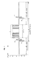
- FIG. 1 shows a portion 100 of an illustrative enhanced National Television System Committee (NTSC) television signal format which incorporates a training sequence 101 during time interval 102 pursuant to the present invention.
- NSC National Television System Committee
- SECAM Sequence Electronique Couleur Avec Memoire
- PAL Phase Alternation Line
- HDTV High Definition Television
- sequence 101 includes 255 symbols which are transmitted at a rate of 7.160 x 10⁶ symbols/second so that time interval 102 has a duration of 35.6 x 10 ⁇ 6 seconds ( ⁇ s).
- sequence 101 is a pseudorandom sequence.
- sequence 101 is advantageously transmitted during the 63.56 ⁇ s horizontal line period 103 which extends between horizontal synchronization pulses 104 and 105.
- Horizontal period 103 is one of a plurality of line periods in a vertical blanking interval in a video frame. Incorporation of the training sequence in the unused time interval in horizontal line period 103 advantageously does not require any alteration of the television signals transmitted before and after sequence 101.
- Envelopes 106 and 107 represent the color bursts in an NTSC format which respectively follow pulses 104 and 105. Within intervals 109 and 110, the signals in the NTSC format are known and provide well-known functions unconnected with the present invention.
- Interval 109 must be at least as long as the maximum delay of any postcursor ghosts and interval 110 must be at least as long as the sum of the maximum postcursor ghost delay and precursor ghost delay.
- the former delay is typically represented by a positive time value and the latter delay is typically represented by a negative time value.
- the sum of the maximum postcursor ghost delay and precursor ghost delay time values, ignoring any algebraic sign, is hereinafter referred to as the expected range of signal dispersion delay.
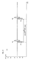
- FIG. 2 shows a portion 200 of the illustrative NTSC television signal format wherein portion 200 succeeds portion 100 and includes a horizontal line period 201 within a vertical blanking interval.
- Horizontal line period 103 is disposed between horizontal synchronization pulses 202 and 203.
- Envelopes 204 and 205 represent color bursts and are identical to envelopes 106 and 107 of FIG. 1. It should be noted that portions 100 and 200 are identical except that the training sequence 101 is not transmitted during horizontal line period 201.
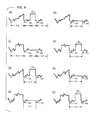
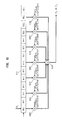
- FIG. 3 shows the periodic nature of the transmission of training sequence 101 within eight portions 300-307 of an NTSC television signal format.
- Each of portions 300 through 307 has the same time duration and respectively includes one horizontal line period 308 through 315 in eight successive vertical blanking intervals.
- Each such horizontal line period is disposed between a pair of horizontal synchronization pulses 104 and 105.
- training sequence period as a time interval within one horizontal line period of each vertical blanking interval.
- the training sequence 101 or a zero dc signal is transmitted. Accordingly, the designations 308 through 315 in FIG. 3 designate this training sequence period.
- the signals surrounding any training sequence period are different from those surrounding an immediately following training sequence period.
- the signals in intervals 316 and 317, which immediately precede and succeed training sequence period 308, are different from those in intervals 318 and 319, which immediately precede and succeed training sequence period 309.
- Training sequence period 309 occurs during a vertical blanking interval immediately following the vertical blanking interval that includes training sequence period 308.
- the signals surrounding any given training sequence period are identical to those surrounding the fourth next training sequence period after the given training sequence period.
- portions 300 and 304 are identical but for the training sequence 101. This identity also exists between portions 301 and 305, portions 302 and 306, and between portions 303 and 307.
- training sequence 101 could be recovered in the receiver by subtracting portion 304 from portion 300, subtracting portion 301 from portion 305, subtracting portion 306 from portion 302 and subtracting portion 303 from portion 307. It is this process of pairing the above-described signal portions, each including a training sequence period, which is used in a receiver constructed pursuant to the present invention.
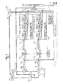
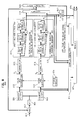
- the transmitted information signal which in the illustrative embodiment is a conventional NTSC formatted signal, is generated by information source 401. This signal is then coupled to signal gateway 405 under the control of timing signals from timing generator 403.
- Training sequence generator 402 generates training sequence 101 within horizontal line periods 308, 310, 313 and 315 under the control of timing signals from timing signal generator 403 and couples these sequences to signal gateway 405.
- each of these pseudorandom sequences is spectrally shaped by raised cosine transmit filter 404 before being coupled to signal gateway 405.
- Gateway 405 selectively couples the signals from source 401 or generator 402 to modulator 406 which provides vestigial sideband (VSB) amplitude modulation in the illustrative NTSC television application, or quadrature amplitude modulation (QAM) in other communication systems.
- VSB vestigial sideband
- QAM quadrature amplitude modulation
- the transmit filter 404 advantageously includes tapped delay line 407, digital-to-analog (D/A) converter with a sample held circuit 408 and an analog low-pass filter (LPF) 409 connected in series. Tapped delay line 407 and D/A converter 408 are clocked at four times the symbol rate (F c ). Analog LPF 409 advantageously eliminates out-of-band signal energy.
- FIGs. 5 and 6 respectively show alternate embodiments of a baseband receiver 500 and 600 which incorporate the present invention.
- the received modulated signal incorporating training sequence 101 is coupled via lead 501 through automatic gain control (AGC) circuit 502 to demodulators 503 and 504.
- AGC automatic gain control
- Each demodulator multiplies the received signal by carrier signals generated by carrier source 505.
- One of these carrier signals is represented by cos ( ⁇ ct + ⁇ e ) while the other is represented by sin ( ⁇ ct + ⁇ e ), where ⁇ c is the carrier frequency used in the transmitter modulator of FIG. 4 and ⁇ e is the phase angle between the carrier signals supplied by carrier source 504 and those utilized by the transmitter modulator.
- Each demodulator output is coupled through low-pass filters (LPF) 506 and 507 to analog-to-digital converters (A/D) 508 and 509.
- LPF low-pass filters
- A/D analog-to-digital converters
- the digital outputs of these converters are supplied to a complex equalizer 510, which removes distortion in the received signal so as to accurately recover the transmitted information signal and provide a pair of output signals 511 for further conventional television processing.
- the term "complex”, with reference to equalizer 510 refers to the fact that this equalizer utilizes coefficients which are complex numbers, i.e., they have a real and an imaginary component.
- the digital outputs of converters 508 and 509 are also coupled to store-and-subtraction circuits 512 and 513.
- the function of store-and-subtraction circuits 512 and 513 is to recover the training sequence 101 from the received signal by storing the paired waveforms of FIG. 3, i.e., 300 and 304, 301 and 305, 302 and 306, and 303 and 307, and then subtracting one waveform in each pair from the other.
- circuits 512 and 513 are periodically enabled by timing circuitry 514.
- the recovered training sequences recovered by circuits 512 and 513 are respectively designated as S I and S Q .
- Correlators 515 and 516 are designed to produce an output pulse upon detecting the training sequence. These output pulses, along with the correlator output at other times, are replicated three times within shift-and-add circuitry 517 and 518 at a spacing equal to the length of training sequence. The correlator output pulses and their replications at the training sequence duration produces signals P I and P Q . Combiner 519 receives the signals P I and P Q and produces the sum of the square of these signals. This sum is designated as P. Logic circuitry 520 determines the amplitude and delay characteristics of the signal dispersion in response to signal P.
- the use of the shift-and-add circuitry has the effect of advantageously reproducing the correlator output pulses as if training sequence 101 were transmitted four times in succession. While this could be done, such successive transmission of the training sequence whose duration is at least equal to the range of signal dispersion delay can require a greater time duration than is available. This is particularly true in the case of a conventionally transmitted television signal, such as NTSC, PAL or SECAM wherein the intervals not used for other signal transmission are not long enough for such successive training sequence transmission.
- amplitude and delay characteristics determined by logic circuitry 520 can be made using only a single correlator, e.g., correlator 515 and its associated single shift-and-add circuit 517, and, therefore, use of correlator 516, shift-and-add circuitry 518 and combiner 519 can be eliminated, the use of both correlators and the combiner advantageously provides a mechanism for adjusting the carrier phase produced by carrier source 505 and the automatic gain control provided by AGC circuit 502.
- use of both signals P I and P Q allows the estimation of ghost characteristics while carrier phase adjustment is still taking place.
- Estimation of the correct carrier phase can be determined by using P I and P Q by well-known means within phase estimator 521 which approximate the arc tangent of P Q /P I . Adjustment of the carrier phase can then be readily provided by coupling the estimated carrier phase, designated as ⁇ e , appearing at the output of the phase estimator to carrier source 505. Similarly, by using the signal P, it is well-known that the amplitude of the received signal can be estimated so as to correct the gain of the receiver. In FIG. 5, signal P is coupled to AGC circuit 502 to provide this gain adjustment.
- the amplitude and delay characteristics provided by logic circuitry 520 along with signals P I and P Q are coupled to complex equalizer 510 wherein they are used to adjust the operation thereof. Specifically, in well-known fashion, the amplitude and delay characteristics are used to determine which equalizer coefficients are non-zero and signals P I and P Q are used to adjust the values of these non-zero coefficients.
- the receiver embodiment shown in FIG. 6 is identical in function and operation to that already described in reference to FIG. 5 except that the serial connection of the correlators and shift-and-add circuitry is reversed. As a result, the training sequences are replicated in FIG. 6 as opposed to replicating the correlator output in FIG. 5. This reversal is equivalent.
- FIG. 7 An illustrative output of the inphase shift-and-add circuitry 517 of FIG. 5, designated as P I , is shown in FIG. 7.
- the output of the quadrature shift-and-add circuitry 518 and designated as P Q is related to P I by a function of the phase shift of the communications medium through which the received signal has propagated.
- a correlator is designed to provide a large amplitude output pulse upon detecting a training sequence. At other times, the correlator output may be ambiguous and the correlator output amplitude is substantially less than when the training sequence is detected.
- Signal P I includes four signal peaks 701 through 704 wherein each peak represents a training sequence or its replicas generated by shift-and-add circuitry of FIG. 5. These peaks are spaced apart by 35.6 ⁇ s time intervals. It should be noted that the intervals between peaks 701 and 702 and between peaks 703 and 704 are respectively corrupted by incompletely correlated postcursor and precursor ghosts of the training sequence. These incompletely correlated postcursor and precursor ghosts are respectively represented by waveforms 705 and 706. The presence of such incompletely correlated ghosts lessens the ability to clearly discern ghost characteristics in those portions of intervals 707 and 708 containing waveforms 705 and 706.
- either one of these intervals could be used to determine signal dispersion characteristics and, consequently, the shift-and-add circuitry in the receiver need only provide at least one replica of its input. It is however, advantageous, for such circuitry to provide three replicas of its input signal so as to provide the four illustrated peaks 701 through 704 and thereby provide buffer intervals 707 and 708 for an innermost interval 709, designated as a "quiet zone". Such buffer intervals sufficiently separate quiet zone 709 in time from incompletely correlated ghosts so that it is devoid of all ghost signals except those of the transmitted training sequence that undergo full correlation.
- Such ghosts can be either postcursor ghosts, i.e., they are received after the training sequence, or precursor ghosts, i.e., they arrive at the receiver prior to the transmitted training sequence.
- FIG. 7 depicts one such postcursor ghost as signal peak 710 which is located at a time interval 711 following peak 702 and one precursor ghost by peak 712 which is located at a time interval 713 preceding peak 703.
- the methodology used by the present invention and provided within logic circuitry 519 is to determine the amplitude of any ghost by using amplitude comparators which determine the presence of any signals in the quiet zone above a predetermined level and the magnitude of such signals. The delay of any such ghost is then determined by the location of any detected signal above this threshold relative to peaks 702 or 703.
- duration of quiet zone 709 extends for at least the range extending from the maximum delayed precursor ghost, typically designated by a negative time value, to the maximum delayed postcursor ghost, which is typically designated by a positive time value.
- FIGs. 8 and 9 show alternate embodiments of a passband receiver which incorporates the present invention.
- the received QAM signal on lead 801 is coupled through AGC circuitry 802 to A/D converter 803 and thence to passband Hilbert filter pair 804 and 805.
- Filters 804 and 805 provide outputs which are coupled to complex equalizer 810 and to store-and-subtraction circuits 812 and 813.
- the outputs of complex equalizer 810 are connected to rotator 825 to produce the transmitted information signals on outputs 826.
- FIG. 9 is similar in operation to FIG. 8 but for the reversal in the series connection of shift-and-add circuitry 817 and 818 and correlators 815 and 816.
- the correlator filter coefficients be binary numbers corresponding to those in the training sequence since such coefficients can have only one of two values, such as +1 and -1, and implementation is thereby simplified.
- the use of such binary coefficients in both the correlator and the transmitter training sequence generator can produce dc bias in the quiet zones.
- Such dc bias which is inherent due to the autocorrelation nature of a pseudorandom sequence, can be eliminated using well-known techniques. For example, in one such technique the dc bias can be measured and then subtracted from P I and P Q or from the signal combiner output signal P. In another technique, the dc bias can be eliminated by passing P I and P Q or P through a properly chosen dc blocking filter (not shown), such as those which subtract a delayed version of the signal from the signal itself.
- a modified pseudorandom sequence can be transmitted in lieu of a pseudorandom sequence.
- a dc constant is added to each symbol of a pseudorandom sequence so that the transmitted symbols are either zero or a positive value rather than the equal positive or negative values of the original pseudorandom sequence.
- the advantage of using a modified pseudorandom sequence is that, unlike the original pseudorandom sequence, there is no dc bias in any quiet zone at the output of a correlator. Accordingly, it is preferable to utilize both binary correlators and modified pseudorandom training sequences in the preferred embodiment of the present invention.
- a pseudorandom sequence having +1 and -1 symbol values is transmitted and the coefficients of the binary correlator take values of either +1 or 0 instead of the +1 and -1 values.
- A/D converter 508 store-and-subtract 512, correlator 515, and shift-and-add circuitry 517 to operate at a rate which is a multiple, n, of the symbol rate, where n is an integer ⁇ 1, in order to provide higher resolution of the signal dispersion delay.
- the correlator as shown in FIG. 10.
- the correlator e.g., 515
- the correlator is implemented by utilizing a tapped delay line 1001, clocked at twice the symbol rate, 2F c , multipliers 1002 and summer 1003.
- Each multiplier utilizes a fixed correlation coefficient which multiplies the symbol value stored in one of the taps of delay line 1001.
- the delay line taps which are combined by summer 1003 are spaced apart by the symbol rate.
- the intermediate taps are not associated with a multiplier and therefore are not inputted to summer 1003.
- the correlation coefficients are either +1, -1 or +1, 0.
- the multipliers 1002 can be realized by pass through elements for a +1 multiplication, sign inversion elements for a -1 multiplication, and signal blocking elements for a 0 multiplication.
Landscapes
- Engineering & Computer Science (AREA)
- Multimedia (AREA)
- Signal Processing (AREA)
- Health & Medical Sciences (AREA)
- Biomedical Technology (AREA)
- General Health & Medical Sciences (AREA)
- Cable Transmission Systems, Equalization Of Radio And Reduction Of Echo (AREA)
- Testing, Inspecting, Measuring Of Stereoscopic Televisions And Televisions (AREA)
Abstract
Description
- The present invention relates to a technique for determining the characteristics of signal dispersion and, more particularly, to a technique in which a training sequence is transmitted and processed at a receiver so as to create a time interval in which the characteristics of the signal dispersion can be accurately quantified.
- A training sequence is a series of apriori known symbols which are transmitted at predetermined times from a signal transmitter to a signal receiver. Such sequences have long been used to adjust the operation of signal dispersion compensation apparatus in the receiver, such as equalizers, echo cancellers and the like.
- Signal dispersion, such as echoes or signal "ghosts", is an inherent problem in communications systems and the severity of the problem can vary with the system application. For example, signal ghosts or echoes frequently exist in conventional television transmission systems which are highly objectional to the viewer and which can render a high definition television (HDTV) signal unintelligible. Accordingly, compensation for signal dispersion is highly desirable in conventional television systems and, indeed, is required in HDTV and in many other communications applications. Moreover, while signal dispersion compensation apparatus, such as equalizers and cancellers, provides satisfactory compensation, knowledge of the signal dispersion characteristics, e.g., amplitude, delay and phase, is useful for the adjustment of such apparatus during system start-up and operation.
- Prior art techniques exist which can determine the characteristics of signal dispersion. Such techniques typically transmit specific signals, such as pulses or training sequences, which are detected and analyzed in the receiver. These techniques provide satisfactory estimates of the signal dispersion characteristics in applications wherein the dispersion is large in amplitude and short in duration. However, the prior art techniques provide inaccurate results when the signal dispersion is small in amplitude, particularly in the presence of channel noise, jitter or similar impairments, and provide ambiguous results when the signal dispersion is long in duration. These shortcomings have hindered development of communications systems requiring ever-more precise signal dispersion compensation and more precise determination of the signal dispersion characteristics.
- Most recently, as disclosed in a pending U.S. patent application to Chao et al., Serial No. 443,772, filed November 30,1989, and assigned to the present assignee, a technique which overcomes the aforesaid problems of the prior art has been developed which transmits two different training sequences wherein each such training sequence includes a different number of symbols. This technique, while providing greater accuracy than those of the previous prior art, requires a time duration for the transmission of the two different training sequences which is not always available. Therefore, a technique which provides greater accuracy in the determination of small-amplitude and long-duration signal dispersion and which requires less time duration would be desirable.
- The present invention covers the notion of determining the amplitude, phase and delay of signal dispersion by transmitting a training sequence including a plurality of apriori known symbols and having a time duration at least equal to the expected range of signal dispersion delay. At a receiver, the training sequence is recovered and then processed using correlation and signal replication techniques. This processed training sequence is then utilized to determine at least one of the aforesaid signal dispersion characteristics.
- A feature of the present invention is that it is applicable to a variety of different communications systems and is particularly adaptable for television signal transmission wherein the training sequence can be advantageously transmitted during the vertical blanking interval. Another feature of the present invention is that it significantly improves the accuracy of determining the characteristics of signal dispersion when such dispersion is of long duration, has a small amplitude, or is accompanied by channel noise, jitter and similar impairments.
-
- FIGs. 1 and 2 are representations of an illustrative signal format wherein a training sequence is transmitted in accordance with the present invention;
- FIG. 3 is a representation of illustrative signals, including signals which precede and succeed the transmission of the training sequence of FIG. 1, utilized by the disclosed embodiment of the present invention;
- FIGs. 4 is a block-schematic diagram representation of an embodiment of a transmitter which incorporates the present invention;
- FIGs. 5 and 6 are alternate block-schematic diagram representations of embodiments of a baseband receiver which incorporates the present invention;
- FIG. 7 is a representation of an illustrative output signal of the
inphase correlator 515 of FIG. 5; - FIGs. 8 and 9 are alternate block-schematic diagram representations of embodiments of a passband receiver which incorporates the present invention; and
- FIG. 10 is a block-schematic diagram representation of an embodiment of the correlator in FIGs. 5, 6, 8 or 9.
- FIG. 1 shows a
portion 100 of an illustrative enhanced National Television System Committee (NTSC) television signal format which incorporates atraining sequence 101 duringtime interval 102 pursuant to the present invention. At this juncture, it will, of course, be understood that the present invention is not restricted to use in such a television signal format and can be utilized with any television signal format, e.g., Sequence Electronique Couleur Avec Memoire (SECAM), Phase Alternation Line (PAL), and HDTV, as well as signal formats for communications systems other than television transmission. In this illustrative format,sequence 101 includes 255 symbols which are transmitted at a rate of 7.160 x 10⁶ symbols/second so thattime interval 102 has a duration of 35.6 x 10⁻⁶ seconds (µs). Preferably,sequence 101 is a pseudorandom sequence. In addition, as shown,sequence 101 is advantageously transmitted during the 63.56 µshorizontal line period 103 which extends betweenhorizontal synchronization pulses Horizontal period 103 is one of a plurality of line periods in a vertical blanking interval in a video frame. Incorporation of the training sequence in the unused time interval inhorizontal line period 103 advantageously does not require any alteration of the television signals transmitted before and aftersequence 101.Envelopes pulses intervals training sequence 101 by a store-and-subtract process.Interval 109 must be at least as long as the maximum delay of any postcursor ghosts andinterval 110 must be at least as long as the sum of the maximum postcursor ghost delay and precursor ghost delay. The former delay is typically represented by a positive time value and the latter delay is typically represented by a negative time value. The sum of the maximum postcursor ghost delay and precursor ghost delay time values, ignoring any algebraic sign, is hereinafter referred to as the expected range of signal dispersion delay. - FIG. 2 shows a
portion 200 of the illustrative NTSC television signal format whereinportion 200 succeedsportion 100 and includes ahorizontal line period 201 within a vertical blanking interval.Horizontal line period 103 is disposed betweenhorizontal synchronization pulses Envelopes envelopes portions training sequence 101 is not transmitted duringhorizontal line period 201. - FIG. 3 shows the periodic nature of the transmission of
training sequence 101 within eight portions 300-307 of an NTSC television signal format. Each ofportions 300 through 307 has the same time duration and respectively includes one horizontal line period 308 through 315 in eight successive vertical blanking intervals. Each such horizontal line period is disposed between a pair ofhorizontal synchronization pulses - We shall define the term training sequence period as a time interval within one horizontal line period of each vertical blanking interval. During this training sequence period, either the
training sequence 101 or a zero dc signal is transmitted. Accordingly, the designations 308 through 315 in FIG. 3 designate this training sequence period. - It should be noted that in the NTSC signal format, shown in FIG. 3, the signals surrounding any training sequence period are different from those surrounding an immediately following training sequence period. For example, the signals in
intervals 316 and 317, which immediately precede and succeed training sequence period 308, are different from those inintervals training sequence period 309.Training sequence period 309 occurs during a vertical blanking interval immediately following the vertical blanking interval that includes training sequence period 308. However, the signals surrounding any given training sequence period are identical to those surrounding the fourth next training sequence period after the given training sequence period. In this regard, note thatportions training sequence 101. This identity also exists betweenportions portions portions training sequence 101 could be recovered in the receiver by subtractingportion 304 fromportion 300,subtracting portion 301 fromportion 305,subtracting portion 306 fromportion 302 and subtractingportion 303 fromportion 307. It is this process of pairing the above-described signal portions, each including a training sequence period, which is used in a receiver constructed pursuant to the present invention. - Refer now to FIG. 4 which shows a transmitter 400 incorporating the present invention. The transmitted information signal, which in the illustrative embodiment is a conventional NTSC formatted signal, is generated by
information source 401. This signal is then coupled to signalgateway 405 under the control of timing signals fromtiming generator 403.Training sequence generator 402 generatestraining sequence 101 withinhorizontal line periods signal generator 403 and couples these sequences to signalgateway 405. Advantageously, each of these pseudorandom sequences is spectrally shaped by raised cosine transmitfilter 404 before being coupled to signalgateway 405.Gateway 405, illustratively represented by a single-pole, multi-throw switch, selectively couples the signals fromsource 401 orgenerator 402 to modulator 406 which provides vestigial sideband (VSB) amplitude modulation in the illustrative NTSC television application, or quadrature amplitude modulation (QAM) in other communication systems. - The transmit
filter 404 advantageously includes tappeddelay line 407, digital-to-analog (D/A) converter with a sample heldcircuit 408 and an analog low-pass filter (LPF) 409 connected in series. Tappeddelay line 407 and D/A converter 408 are clocked at four times the symbol rate (Fc).Analog LPF 409 advantageously eliminates out-of-band signal energy. - FIGs. 5 and 6 respectively show alternate embodiments of a baseband receiver 500 and 600 which incorporate the present invention. As shown in FIG. 5, the received modulated signal incorporating
training sequence 101 is coupled vialead 501 through automatic gain control (AGC)circuit 502 todemodulators carrier source 505. One of these carrier signals is represented by cos (ωct + ϑe) while the other is represented by sin (ωct + ϑe), where ωc is the carrier frequency used in the transmitter modulator of FIG. 4 and ϑe is the phase angle between the carrier signals supplied bycarrier source 504 and those utilized by the transmitter modulator. - Each demodulator output is coupled through low-pass filters (LPF) 506 and 507 to analog-to-digital converters (A/D) 508 and 509. The digital outputs of these converters are supplied to a
complex equalizer 510, which removes distortion in the received signal so as to accurately recover the transmitted information signal and provide a pair ofoutput signals 511 for further conventional television processing. The term "complex", with reference toequalizer 510, refers to the fact that this equalizer utilizes coefficients which are complex numbers, i.e., they have a real and an imaginary component. The digital outputs ofconverters subtraction circuits - The function of store-and-
subtraction circuits training sequence 101 from the received signal by storing the paired waveforms of FIG. 3, i.e., 300 and 304, 301 and 305, 302 and 306, and 303 and 307, and then subtracting one waveform in each pair from the other. To extract the incoming signal waveform at the appropriate time so as to recover each of these paired waveforms,circuits circuitry 514. The recovered training sequences recovered bycircuits -
Correlators add circuitry P. Logic circuitry 520 determines the amplitude and delay characteristics of the signal dispersion in response to signal P. - It should be noted that the use of the shift-and-add circuitry has the effect of advantageously reproducing the correlator output pulses as if
training sequence 101 were transmitted four times in succession. While this could be done, such successive transmission of the training sequence whose duration is at least equal to the range of signal dispersion delay can require a greater time duration than is available. This is particularly true in the case of a conventionally transmitted television signal, such as NTSC, PAL or SECAM wherein the intervals not used for other signal transmission are not long enough for such successive training sequence transmission. - While the amplitude and delay characteristics determined by
logic circuitry 520 can be made using only a single correlator, e.g.,correlator 515 and its associated single shift-and-add circuit 517, and, therefore, use ofcorrelator 516, shift-and-add circuitry 518 andcombiner 519 can be eliminated, the use of both correlators and the combiner advantageously provides a mechanism for adjusting the carrier phase produced bycarrier source 505 and the automatic gain control provided byAGC circuit 502. In addition, use of both signals PI and PQ allows the estimation of ghost characteristics while carrier phase adjustment is still taking place. - Estimation of the correct carrier phase can be determined by using PI and PQ by well-known means within
phase estimator 521 which approximate the arc tangent of PQ/PI. Adjustment of the carrier phase can then be readily provided by coupling the estimated carrier phase, designated as ϑ̂e, appearing at the output of the phase estimator tocarrier source 505. Similarly, by using the signal P, it is well-known that the amplitude of the received signal can be estimated so as to correct the gain of the receiver. In FIG. 5, signal P is coupled toAGC circuit 502 to provide this gain adjustment. - The amplitude and delay characteristics provided by
logic circuitry 520 along with signals PI and PQ are coupled tocomplex equalizer 510 wherein they are used to adjust the operation thereof. Specifically, in well-known fashion, the amplitude and delay characteristics are used to determine which equalizer coefficients are non-zero and signals PI and PQ are used to adjust the values of these non-zero coefficients. - The receiver embodiment shown in FIG. 6 is identical in function and operation to that already described in reference to FIG. 5 except that the serial connection of the correlators and shift-and-add circuitry is reversed. As a result, the training sequences are replicated in FIG. 6 as opposed to replicating the correlator output in FIG. 5. This reversal is equivalent.
- An illustrative output of the inphase shift-and-
add circuitry 517 of FIG. 5, designated as PI, is shown in FIG. 7. The output of the quadrature shift-and-add circuitry 518 and designated as PQ is related to PI by a function of the phase shift of the communications medium through which the received signal has propagated. As is well known, a correlator is designed to provide a large amplitude output pulse upon detecting a training sequence. At other times, the correlator output may be ambiguous and the correlator output amplitude is substantially less than when the training sequence is detected. - Signal PI includes four
signal peaks 701 through 704 wherein each peak represents a training sequence or its replicas generated by shift-and-add circuitry of FIG. 5. These peaks are spaced apart by 35.6 µs time intervals. It should be noted that the intervals betweenpeaks peaks waveforms intervals waveforms peaks 701 through 704 and thereby providebuffer intervals innermost interval 709, designated as a "quiet zone". Such buffer intervals sufficiently separatequiet zone 709 in time from incompletely correlated ghosts so that it is devoid of all ghost signals except those of the transmitted training sequence that undergo full correlation. Such ghosts can be either postcursor ghosts, i.e., they are received after the training sequence, or precursor ghosts, i.e., they arrive at the receiver prior to the transmitted training sequence. FIG. 7 depicts one such postcursor ghost assignal peak 710 which is located at atime interval 711 followingpeak 702 and one precursor ghost bypeak 712 which is located at atime interval 713 precedingpeak 703. Accordingly, the methodology used by the present invention and provided withinlogic circuitry 519 is to determine the amplitude of any ghost by using amplitude comparators which determine the presence of any signals in the quiet zone above a predetermined level and the magnitude of such signals. The delay of any such ghost is then determined by the location of any detected signal above this threshold relative topeaks quiet zone 709 extends for at least the range extending from the maximum delayed precursor ghost, typically designated by a negative time value, to the maximum delayed postcursor ghost, which is typically designated by a positive time value. - FIGs. 8 and 9 show alternate embodiments of a passband receiver which incorporates the present invention. In these receivers the received QAM signal on
lead 801 is coupled throughAGC circuitry 802 to A/D converter 803 and thence to passbandHilbert filter pair Filters complex equalizer 810 and to store-and-subtraction circuits complex equalizer 810 are connected torotator 825 to produce the transmitted information signals onoutputs 826. The operation of store-and-subtraction circuitry correlators add circuitry combiner 819,logic circuitry 820 andphase estimator 821 are functional equivalents to their counterparts in the baseband receiver. FIG. 9 is similar in operation to FIG. 8 but for the reversal in the series connection of shift-and-add circuitry - In FIGs. 5, 6, 8 and 9, it is preferable that the correlator filter coefficients be binary numbers corresponding to those in the training sequence since such coefficients can have only one of two values, such as +1 and -1, and implementation is thereby simplified. However, the use of such binary coefficients in both the correlator and the transmitter training sequence generator can produce dc bias in the quiet zones. Such dc bias, which is inherent due to the autocorrelation nature of a pseudorandom sequence, can be eliminated using well-known techniques. For example, in one such technique the dc bias can be measured and then subtracted from PI and PQ or from the signal combiner output signal P. In another technique, the dc bias can be eliminated by passing PI and PQ or P through a properly chosen dc blocking filter (not shown), such as those which subtract a delayed version of the signal from the signal itself.
- A modified pseudorandom sequence can be transmitted in lieu of a pseudorandom sequence. In a modified pseudorandom sequence, a dc constant is added to each symbol of a pseudorandom sequence so that the transmitted symbols are either zero or a positive value rather than the equal positive or negative values of the original pseudorandom sequence. The advantage of using a modified pseudorandom sequence is that, unlike the original pseudorandom sequence, there is no dc bias in any quiet zone at the output of a correlator. Accordingly, it is preferable to utilize both binary correlators and modified pseudorandom training sequences in the preferred embodiment of the present invention. For another arrangement, a pseudorandom sequence having +1 and -1 symbol values is transmitted and the coefficients of the binary correlator take values of either +1 or 0 instead of the +1 and -1 values.
- In FIGs. 5, 6, 8 and 9, it is advantageous for A/
D converter 508, store-and-subtract 512,correlator 515, and shift-and-add circuitry 517 to operate at a rate which is a multiple, n, of the symbol rate, where n is an integer ≧ 1, in order to provide higher resolution of the signal dispersion delay. With such an arrangement, it is preferable to implement the correlator as shown in FIG. 10. As illustrated in FIG. 10, the correlator, e.g., 515 , is implemented by utilizing a tappeddelay line 1001, clocked at twice the symbol rate, 2Fc,multipliers 1002 andsummer 1003. Each multiplier utilizes a fixed correlation coefficient which multiplies the symbol value stored in one of the taps ofdelay line 1001. The delay line taps which are combined bysummer 1003 are spaced apart by the symbol rate. The intermediate taps are not associated with a multiplier and therefore are not inputted tosummer 1003. In the preferred embodiments, where a binary correlator is utilized, the correlation coefficients are either +1, -1 or +1, 0. With such coefficients, themultipliers 1002 can be realized by pass through elements for a +1 multiplication, sign inversion elements for a -1 multiplication, and signal blocking elements for a 0 multiplication. - It should, of course, be understood that while the present invention has been disclosed in reference to specific embodiments, numerous other arrangements should be apparent to those of ordinary skill in the art. For example, while the present invention has been disclosed in reference to a VSB or QAM signal, the invention is applicable to any analog or digital communication system regardless of the presence, absence or type of modulation. In addition, the present invention is not limited to pseudorandom or modified pseudorandom training sequences and, indeed, can employ any type of training sequence. Furthermore, the complex equalizer shown in FIGs. 5, 6, 8 and 9 can be positioned so that its outputs are coupled to each correlator input. In such an arrangement, the equalizer serves as a unit impulse fixed filter during system initialization and serves as an adaptive equalizer thereafter.
Claims (26)
- Transmitter apparatus (400) for use in a communications system where signal dispersion has an expected range of delay, said apparatus
CHARACTERISED BY
means (402) for generating a training sequence, said training sequence including a plurality of predetermined symbols and having a duration at least equal to said range of delay, and
means (403,405,406) for transmitting said training sequence in an associated time interval at a predetermined symbol rate. - Apparatus for use in a television signal transmitter wherein the transmitted television signal incorporates horizontal line periods and wherein signal dispersion having an expected range of delay is present in the transmitted television signal after propagation through a communications medium, said apparatus
CHARACTERISED BY
means (402) for generating a training sequence, said training sequence including a number of predetermined symbols and having a duration at least equal to said range of delay, and
means (403,405,406) for transmitting said training sequence in predetermined ones of said horizontal line periods at a predetermined symbol rate. - Apparatus as claimed in claim 2 wherein said transmitting means also serves to transmit video and audio signals.
- Apparatus as claimed in claim 3 wherein said transmitting means serves to transmit said video and audio signals in a predetermined television signal format.
- Apparatus as claimed in claim 1 wherein said transmitting means also serves to transmit an information signal in time intervals surrounding said associated time interval.
- Apparatus as claimed in any preceding claim wherein said training sequence is a pseudorandom sequence.
- Apparatus as claimed in claim 6 wherein said predetermined symbols in said pseudorandom sequence have equal positive and negative values.
- Apparatus as claimed in claim 6 wherein said predetermined symbols in said pseudorandom sequence have values which are zero and nonzero.
- Apparatus as claimed in any one of claim 1 to 5 wherein said training sequence is a modified pseudorandom sequence in which a constant value is added to each predetermined symbol.
- Apparatus as claimed in any preceding claim wherein said transmitting means includes means (404) for spectrally shaping said training sequence prior to transmission.
- Apparatus as claimed in claim 10 wherein said spectrally shaping means includes a tapped delay line clocked at a multiple of said predetermined symbol rate.
- Apparatus as claimed in claim 10 or 11 wherein said spectrally shaping means provides raised cosine spectral shaping.
- Receiver apparatus for use in a communications system wherein any received signal has propagated through a communications medium in which signal dispersion may be present, said receiver apparatus
CHARACTERISED BY
means (515,517), responsive to a received training sequence including a plurality of predetermined symbols occurring at a predetermined symbol rate, for processing said received training sequence using correlation and signal replication, and
means (520) responsive to the processed training sequence for determining at least one characteristic of said signal dispersion. - The apparatus of claim 13 wherein said processing means provides correlation using a clock signal which is n times said predetermined symbol rate, where n is an integer ≧ 1.
- The receiver apparatus of claim 13 wherein said training sequence is a pseudorandom sequence and said processing means is responsive to said pseudorandom sequence.
- The receiver apparatus of claim 13 wherein said processing means correlates said training sequence with a predetermined set of coefficients and replicates said correlated training sequence.
- The apparatus of claim 16 wherein each coefficient is said predetermined set of coefficients is a binary number.
- The apparatus of claim 17 wherein the binary numbers have equal positive and negative values.
- The apparatus of claim 17 wherein the binary numbers have values which are zero and nonzero.
- The receiver apparatus of claim 13 wherein said processing means replicates said received training sequence at least one time and correlates said received training sequence with a predetermined set of coefficients and correlates the replica of said received training sequence with said predetermined set of coefficients.
- The receiver apparatus of claim 13 further including a source (505) of at least one carrier signal and said determining means determines the phase characteristic of said signal dispersion and controls said carrier signal source.
- The receiver apparatus of claim 13 further including an equalizer (510) and said determining means adjusts the operation of said equalizer.
- The receiver apparatus of claim 13 wherein said determining means determines the amplitude and delay characteristics of said signal dispersion.
- The receiver apparatus of claim 13 further including an automatic gain control circuit (502) through which said received training sequence is coupled and said determining means includes means for controlling the gain of said automatic gain control circuit.
- A method of determining at least one characteristic of signal dispersion in a communications system wherein said signal dispersion has an expected range of delay, said method
CHARACTERISED BY
the steps of
generating a training sequence, said training sequence including a number of predetermined symbols and having a duration at least equal to said range of delay,
transmitting said training sequences in an associated time interval,
receiving said training sequence and processing the same using correlation and signal replication, and
determining at least one characteristic of said signal dispersion in response to said processed training sequence. - A communication system comprising a transmitter and a receiver which are separated by a communications medium in which signal dispersion having an expected range of delay may be present, said transmitter
CHARATERISED BY
means for generating a training sequence, said training sequence including a number of predetermined symbols and having a duration at least equal to said range of delay, and
means for transmitting said training sequences in an associated time interval,
and said receiver
CHARACTERISED BY
means, responsive to a received training sequence including a plurality of predetermined symbols, for processing said received training sequence using correlation and signal replication, and
means responsive to the processed training sequence for determining at least one characteristic of said signal dispersion.
Applications Claiming Priority (3)
| Application Number | Priority Date | Filing Date | Title |
|---|---|---|---|
| US49301790A | 1990-03-13 | 1990-03-13 | |
| US493017 | 1990-03-13 | ||
| CA 2111170 CA2111170C (en) | 1990-03-13 | 1993-12-10 | Technique for determining signal dispersion characteristics in communications systems |
Publications (3)
| Publication Number | Publication Date |
|---|---|
| EP0446523A2 true EP0446523A2 (en) | 1991-09-18 |
| EP0446523A3 EP0446523A3 (en) | 1992-06-03 |
| EP0446523B1 EP0446523B1 (en) | 1995-09-27 |
Family
ID=25676844
Family Applications (1)
| Application Number | Title | Priority Date | Filing Date |
|---|---|---|---|
| EP90313332A Expired - Lifetime EP0446523B1 (en) | 1990-03-13 | 1990-12-07 | Determination of dispersion characteristics of a communication channel from a received training sequence processed by correlation and replication |
Country Status (5)
| Country | Link |
|---|---|
| EP (1) | EP0446523B1 (en) |
| JP (1) | JPH04220892A (en) |
| KR (1) | KR940008123B1 (en) |
| CA (1) | CA2033931C (en) |
| DE (1) | DE69022715T2 (en) |
Cited By (3)
| Publication number | Priority date | Publication date | Assignee | Title |
|---|---|---|---|---|
| US5406586A (en) * | 1991-07-09 | 1995-04-11 | At&T Corp. | Signal correlation technique |
| US5479444A (en) * | 1993-03-09 | 1995-12-26 | Nokia Mobile Phones Ltd. | Training sequence in digital cellular radio telephone system |
| US6084862A (en) * | 1997-09-26 | 2000-07-04 | Telefonaktiebolaget Lm Ericsson | Time dispersion measurement in radio communications systems |
Family Cites Families (2)
| Publication number | Priority date | Publication date | Assignee | Title |
|---|---|---|---|---|
| EP0212839B2 (en) * | 1985-07-16 | 1994-10-19 | Matsushita Electric Industrial Co., Ltd. | Ghost cancelling reference signal transmission/reception system |
| JP2594639B2 (en) * | 1989-03-23 | 1997-03-26 | 株式会社日立製作所 | Television image reception signal waveform distortion detection method, and television image signal transmission device and reception device used therefor |
-
1990
- 1990-12-07 EP EP90313332A patent/EP0446523B1/en not_active Expired - Lifetime
- 1990-12-07 DE DE69022715T patent/DE69022715T2/en not_active Expired - Fee Related
-
1991
- 1991-01-10 CA CA002033931A patent/CA2033931C/en not_active Expired - Fee Related
- 1991-03-07 KR KR1019910003643A patent/KR940008123B1/en not_active Expired - Fee Related
- 1991-03-11 JP JP3069500A patent/JPH04220892A/en active Pending
Cited By (3)
| Publication number | Priority date | Publication date | Assignee | Title |
|---|---|---|---|---|
| US5406586A (en) * | 1991-07-09 | 1995-04-11 | At&T Corp. | Signal correlation technique |
| US5479444A (en) * | 1993-03-09 | 1995-12-26 | Nokia Mobile Phones Ltd. | Training sequence in digital cellular radio telephone system |
| US6084862A (en) * | 1997-09-26 | 2000-07-04 | Telefonaktiebolaget Lm Ericsson | Time dispersion measurement in radio communications systems |
Also Published As
| Publication number | Publication date |
|---|---|
| JPH04220892A (en) | 1992-08-11 |
| DE69022715T2 (en) | 1996-05-23 |
| DE69022715D1 (en) | 1995-11-02 |
| EP0446523B1 (en) | 1995-09-27 |
| KR940008123B1 (en) | 1994-09-02 |
| CA2033931C (en) | 1995-06-27 |
| KR910017878A (en) | 1991-11-05 |
| EP0446523A3 (en) | 1992-06-03 |
Similar Documents
| Publication | Publication Date | Title |
|---|---|---|
| US5260972A (en) | Technique for determining signal dispersion characteristics in communications systems | |
| EP0430531B1 (en) | Technique for determining signal dispersion characteristics in communications systems | |
| US5406586A (en) | Signal correlation technique | |
| US5799037A (en) | Receiver capable of demodulating multiple digital modulation formats | |
| CA2079292C (en) | Fast response matched filter receiver with decision feedback equalizer | |
| US4262360A (en) | Method and device for detecting a pseudo-random sequence of carrier phase changes of 0° and 180° in a data receiver | |
| WO1997030511A1 (en) | Apparatus for generating timing signal for a digital television signal receiver | |
| JPS5817794A (en) | Waveform distorsion reducing device | |
| KR0163729B1 (en) | Phase detecting method and ptl of vsb modulation system | |
| US4253186A (en) | Method and device for detecting a pseudo-random sequence of two symbols in a data receiver employing double sideband-quadrature carrier modulation | |
| US6148037A (en) | Sampling timing phase error detector for VSB modulation signal | |
| KR100273763B1 (en) | Tv reception apparatus using same ghost-cancellarion circuitry for receiving different types of tv signals | |
| EP0446523B1 (en) | Determination of dispersion characteristics of a communication channel from a received training sequence processed by correlation and replication | |
| US5815536A (en) | Multivalue digital transmission system | |
| US6430243B1 (en) | Symbol sign directed phase detector | |
| US3581207A (en) | Joint setting of demodulating carrier phase, sampling time and equalizer gain parameters in synchronous data transmission systems | |
| CA2111170C (en) | Technique for determining signal dispersion characteristics in communications systems | |
| Kim et al. | A symbol timing recovery using the segment sync data for the digital HDTV GA VSB system | |
| US5210607A (en) | Ghost reduction device for removing ghost components of a television signal | |
| EP0228260B1 (en) | Signal offset circuitry for digital deghosting system | |
| KR100260422B1 (en) | Digital tv signal receiver | |
| Wang | Complex-valued ghost cancellation reference signal for TV broadcasting | |
| Hoggarth | Echo cancelling for enhanced PAL | |
| JP2570116B2 (en) | Transmission device | |
| JPS6138675B2 (en) |
Legal Events
| Date | Code | Title | Description |
|---|---|---|---|
| PUAI | Public reference made under article 153(3) epc to a published international application that has entered the european phase |
Free format text: ORIGINAL CODE: 0009012 |
|
| AK | Designated contracting states |
Kind code of ref document: A2 Designated state(s): DE FR GB IT NL SE |
|
| PUAL | Search report despatched |
Free format text: ORIGINAL CODE: 0009013 |
|
| AK | Designated contracting states |
Kind code of ref document: A3 Designated state(s): DE FR GB IT NL SE |
|
| 17P | Request for examination filed |
Effective date: 19921119 |
|
| RAP3 | Party data changed (applicant data changed or rights of an application transferred) |
Owner name: AT&T CORP. |
|
| 17Q | First examination report despatched |
Effective date: 19940628 |
|
| GRAA | (expected) grant |
Free format text: ORIGINAL CODE: 0009210 |
|
| AK | Designated contracting states |
Kind code of ref document: B1 Designated state(s): DE FR GB IT NL SE |
|
| ITF | It: translation for a ep patent filed | ||
| REF | Corresponds to: |
Ref document number: 69022715 Country of ref document: DE Date of ref document: 19951102 |
|
| ET | Fr: translation filed | ||
| PLBE | No opposition filed within time limit |
Free format text: ORIGINAL CODE: 0009261 |
|
| STAA | Information on the status of an ep patent application or granted ep patent |
Free format text: STATUS: NO OPPOSITION FILED WITHIN TIME LIMIT |
|
| 26N | No opposition filed | ||
| REG | Reference to a national code |
Ref country code: FR Ref legal event code: TP |
|
| REG | Reference to a national code |
Ref country code: GB Ref legal event code: 732E |
|
| REG | Reference to a national code |
Ref country code: GB Ref legal event code: IF02 |
|
| PGFP | Annual fee paid to national office [announced via postgrant information from national office to epo] |
Ref country code: NL Payment date: 20041117 Year of fee payment: 15 |
|
| PGFP | Annual fee paid to national office [announced via postgrant information from national office to epo] |
Ref country code: SE Payment date: 20041221 Year of fee payment: 15 |
|
| PG25 | Lapsed in a contracting state [announced via postgrant information from national office to epo] |
Ref country code: IT Free format text: LAPSE BECAUSE OF NON-PAYMENT OF DUE FEES Effective date: 20051207 |
|
| PG25 | Lapsed in a contracting state [announced via postgrant information from national office to epo] |
Ref country code: SE Free format text: LAPSE BECAUSE OF NON-PAYMENT OF DUE FEES Effective date: 20051208 |
|
| PG25 | Lapsed in a contracting state [announced via postgrant information from national office to epo] |
Ref country code: NL Free format text: LAPSE BECAUSE OF NON-PAYMENT OF DUE FEES Effective date: 20060701 |
|
| EUG | Se: european patent has lapsed | ||
| NLV4 | Nl: lapsed or anulled due to non-payment of the annual fee |
Effective date: 20060701 |
|
| PGFP | Annual fee paid to national office [announced via postgrant information from national office to epo] |
Ref country code: FR Payment date: 20061220 Year of fee payment: 17 |
|
| PGFP | Annual fee paid to national office [announced via postgrant information from national office to epo] |
Ref country code: GB Payment date: 20061222 Year of fee payment: 17 |
|
| PGFP | Annual fee paid to national office [announced via postgrant information from national office to epo] |
Ref country code: DE Payment date: 20070131 Year of fee payment: 17 |
|
| GBPC | Gb: european patent ceased through non-payment of renewal fee |
Effective date: 20071207 |
|
| PG25 | Lapsed in a contracting state [announced via postgrant information from national office to epo] |
Ref country code: DE Free format text: LAPSE BECAUSE OF NON-PAYMENT OF DUE FEES Effective date: 20080701 |
|
| REG | Reference to a national code |
Ref country code: FR Ref legal event code: ST Effective date: 20081020 |
|
| PG25 | Lapsed in a contracting state [announced via postgrant information from national office to epo] |
Ref country code: GB Free format text: LAPSE BECAUSE OF NON-PAYMENT OF DUE FEES Effective date: 20071207 |
|
| PG25 | Lapsed in a contracting state [announced via postgrant information from national office to epo] |
Ref country code: FR Free format text: LAPSE BECAUSE OF NON-PAYMENT OF DUE FEES Effective date: 20071231 |