EP0446483A2 - Catalytic gas sensor - Google Patents
Catalytic gas sensor Download PDFInfo
- Publication number
- EP0446483A2 EP0446483A2 EP90125393A EP90125393A EP0446483A2 EP 0446483 A2 EP0446483 A2 EP 0446483A2 EP 90125393 A EP90125393 A EP 90125393A EP 90125393 A EP90125393 A EP 90125393A EP 0446483 A2 EP0446483 A2 EP 0446483A2
- Authority
- EP
- European Patent Office
- Prior art keywords
- gas sensor
- sensor according
- catalytic gas
- membrane
- thermocouple
- Prior art date
- Legal status (The legal status is an assumption and is not a legal conclusion. Google has not performed a legal analysis and makes no representation as to the accuracy of the status listed.)
- Withdrawn
Links
Images


Classifications
-
- G—PHYSICS
- G01—MEASURING; TESTING
- G01N—INVESTIGATING OR ANALYSING MATERIALS BY DETERMINING THEIR CHEMICAL OR PHYSICAL PROPERTIES
- G01N27/00—Investigating or analysing materials by the use of electric, electrochemical, or magnetic means
- G01N27/02—Investigating or analysing materials by the use of electric, electrochemical, or magnetic means by investigating impedance
- G01N27/04—Investigating or analysing materials by the use of electric, electrochemical, or magnetic means by investigating impedance by investigating resistance
- G01N27/14—Investigating or analysing materials by the use of electric, electrochemical, or magnetic means by investigating impedance by investigating resistance of an electrically-heated body in dependence upon change of temperature
- G01N27/16—Investigating or analysing materials by the use of electric, electrochemical, or magnetic means by investigating impedance by investigating resistance of an electrically-heated body in dependence upon change of temperature caused by burning or catalytic oxidation of surrounding material to be tested, e.g. of gas
Definitions
- the present invention relates to a catalytic gas sensor with a heating device, a temperature sensor device and a catalytically active surface layer, on which the gas to be detected reacts catalytically exothermic and leads to a temperature increase dependent on the gas concentration, which can be detected electrically by the temperature sensor device, according to the preamble of Claim 1.
- a catalytic gas sensor of the type mentioned is known from DE-A1-35 19 397.
- the known gas sensor comprises two detector elements for each gas mixture to be detected, of which only one has a catalytically active surface layer and is sensitive to the gas mixture to be detected, while the other has no calorimetric sensitivity as a reference element.
- the known gas sensor therefore requires a sensitive detector element and a reference element for each type of gas to be detected, which results in a complex gas sensor structure.
- the object of the present invention is to develop a catalytic gas sensor of the type mentioned at the outset in such a way that it is suitable for detecting different types of gas and for determining the respective gas concentration with a simplified construction.
- the gas sensor according to the invention it is possible to detect different types of gas by means of two detection areas with different sensitivities and by means of a temperature sensor device which is arranged both on the detection area with the first sensitivity and on the detection area with the second sensitivity, for which no reference element is required .
- the detection areas of different sensitivities can be made from different surface layers Catalyst materials and / or formed by areas heated to different temperatures.
- the invention is based on the knowledge that these ranges of different sensitivities allow different types of gas to be recognized and the gas concentration to be improved, since the temperature dependence of the chemical conversion of different gases differs from one type of gas to another and since different catalysts also react in one type of gas dependent on different ways. For this reason, an improved detection of the gas type and gas concentration can be achieved by a signal processing arrangement downstream of the sensor.
- the gas sensor according to the invention works with two measuring points of different sensitivity, the influence of disturbance variables, such as the flow rate and the temperature of the gas to be examined, can be largely compensated for.
- the gas sensor according to the invention enables reference formation with an integrated structure without the need for additional manufacturing steps compared to the manufacturing processes required for the known gas sensors mentioned at the outset.
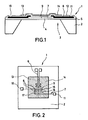
- the catalytic gas sensor shown in vertical section in FIG. 1 is designated in its entirety by the reference number 1 and essentially comprises a carrier body 2 consisting of silicon, which has a recess 3 which is spanned by a membrane 4.
- the membrane 4 essentially consists of a nitride layer 5, on which, as can also be seen from FIG. 2, a meandering heating resistor 6 made of polysilicon with contact points made of aluminum and a thermocouple 7 are arranged.
- the thermocouple 7 consists of two different types of thermocouple sections 8, 9 connected in series, which consist of different materials.
- the first thermocouple sections 8 consist of an aluminum layer which extends from contact holes 10, 11 to the second thermocouple sections 9 made of polysilicon.
- thermocouple sections 8, 9 can also consist of other material pairs, such as chromium and aluminum as well as polysilicon and gold.
- a passivation layer 12 which can be formed by a plasma nitride layer, lies above the structures of the heating resistor 6 and the thermocouple 7 just described.
- Above the passivation layer as indicated in FIG. 2 by cross-hatching, there are first and second surface layers made of a first and a second catalyst material. Metals such as platinum and palladium or oxides come in as catalyst materials Consider.
- the first and second surface layers 13, 14 consist of platinum and palladium.
- the membrane 4 is partially covered by the first surface layer 13 made of the first catalyst material and partially covered by the second surface layer 14 made of the second catalyst material.
- thermocouple 8 forming the temperature sensor device extends over the first surface layer 13 made of the first catalyst material to the second surface layer 14 made of the second catalyst material.
- the contact points 15, 16, 17 of the thermocouple sections 8, 9 lie alternately on the first and second surface layers 13, 14, so that the temperature difference between the first and second surface layers 13, 14 is detected by the thermocouple 7.
- a silicon wafer which has a 100 orientation, serves as the starting material for the carrier body 2.
- the silicon wafer which later forms the carrier body 2, is thermally oxidized and then provided on both sides with a nitride layer, for example 300 nm thick.
- Chemical deposition from the gas phase at low pressures (LPCVD) can be used for this.
- a further LPCVD process is used to deposit a 400 nm thick polysilicon layer, for example, which is structured by photolithography and wet chemical etching. The polysilicon layer on the back of the silicon wafer is removed.
- This polysilicon layer serves as the material for the heating resistor 6 and for the second thermocouple section 9.
- the conductor width of the heating element 6 and thermocouple 7 is typically between 0.01 and 0.03 mm.
- an aluminum layer is deposited, which represents the first thermocouple sections 8 and the contact points of the heating resistor.
- Nickel can also be used to produce the heating resistor 6 or the measuring resistors to be explained later. In this case, gold is sputtered on or vapor deposited to produce contacts.
- the desired configurations are again structured using photolithography and a suitable etching technique.
- the passivation layer 12 is produced by a plasma-assisted chemical vapor deposition process (PECVD).
- PECVD plasma-assisted chemical vapor deposition process
- the plasma nitride layer deposited by the PECVD method has a thickness of 300 to 700 nm.
- the passivation layer 12 is opened by photo technology and dry etching.
- the nitride layer (not shown) on the back of the wafer is structured into an etching mask by dry etching.
- Anisotropic etching exposes recess 3 to define a rectangular membrane with dimensions from 0.3 x 0.3 to 3 x 3 mm. This can be done using a KOH solution.
- an isotropic etching such as HF / HNO3, a circular or other membrane shape can be produced.
- the catalyst materials are evaporated to produce the surface layers 13, 14.
- the catalyst materials can also be applied by means of sputtering.
- metals such as platinum and palladium or oxides are suitable as catalyst materials for this.
- the resulting chips are applied to suitable bases (not shown).
- the catalyst materials for producing the surface layers 13, 14 can also be applied after the sawing.
- the heating resistor 6 is designed in an elongated, non-angled form and lies with its meandering shape symmetrical to the boundary line between the two surface layers 13, 14.
- thermocouple 7 instead of the thermocouple 7, two measuring resistors 18, 19 are provided, each of which is used to detect the temperature of the first or second surface layer 13, 14.
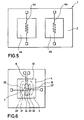
- the carrier body 2 has two recesses 3a, 3b, which are each spanned by a membrane 4a, 4b.
- Each membrane is provided with its own heating resistor 6a, 6b.
- the thermocouple 7 with the first and second thermocouple sections 8, 9 is arranged such that their contact points alternate are arranged on the first or second membrane 4a, 4b for measuring the different membrane temperatures.
- the thermocouple 7 detects the temperature difference between the two membranes 4a, 4b, which in the exemplary embodiment shown here are covered over the entire surface with a first or second catalyst material.
- the fourth embodiment of the gas sensor 1 according to the invention shown in FIG. 5 differs from the third embodiment according to FIG. 4 in that the two resistors 6a, 6b serve both as heating resistors and as measuring resistors. For this reason, the thermocouple 7 for detecting the temperature of the membranes 4a, 4b can be omitted in this embodiment.
- the membrane 4 is only coated with a uniform surface layer 13 made of a single catalyst material.
- detection areas of different sensitivities are not realized by using different catalyst materials in the area of the measuring points of the thermocouple 7, but by heating the detection areas to different temperature levels.
- the detection areas are realized by isotherms 20, 21 at the location of the respective contact points 22, 23, 24 or 25, 26, 27.
- these isotherms 20, 21 are formed by regions of different distance from the heating resistor 6 within the membrane 4.
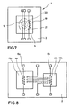
- the temperature difference between the isotherms 20, 21 is not detected by means of a thermocouple 7, as is the case in the embodiment according to FIG. 6, but by means of two measuring resistors 18, 19.
- the heating resistor is stretched here and is not angled.
- the embodiment according to FIG. 8 differs from the embodiment according to FIG. 4 only in that both membranes are coated with surface layers 13a, 13b made of the same catalyst material.
- the different sensitivities of the detection areas are not realized by different catalyst materials, but by different temperatures of the membranes 4a, 4b, which are determined by corresponding heating powers of the heating resistors 6a, 6b.
- the two resistors 6a, 6b on the two membranes 4a, 4b which are coated with surface coatings 13a, 13b made of the same catalyst material, serve both as measuring resistors and as heating resistors. Therefore, in contrast to the embodiment according to FIG. 8, the thermocouple 7 can be omitted in this embodiment.
- the two membranes 4a, 4b are operated at different temperatures due to correspondingly different heating powers of the resistors 6a, 6b.
- the lower temperature of the second membrane 4b shown on the right compared to the first membrane 4a shown on the left can also be achieved by a smaller lateral dimension of the second membrane 4b compared to that of the first membrane 4a with the same heating power of the two resistors 6a, 6b be realized.
- an increased sensitivity of the gas sensor can be brought about by the fact that its membrane 4 is not only provided on the front with surface layers 13, 14 made of a first or second catalyst material, but rather is also provided on the back with surface layers 28, 29 made of the first and second catalyst material in such a way that the same catalyst materials face each other on both sides of the membrane.
- a different sensitivity between the two detection areas can also be brought about by providing them with different catalyst materials and operating them at different temperatures.
- the gas sensor according to the invention can thus be manufactured as an integrated chip which is characterized by low manufacturing costs, a low power requirement in the order of magnitude of only 20 to 100 mW, high sensor accuracy, low long-term drift and reference formation without additional manufacturing steps with high miniaturizability.
- thermocouples or further measuring resistors can be arranged on the membranes in such embodiments.
- thermocouples or measuring resistors More than two isotherms can be used on the membranes, additional thermocouples or measuring resistors being required here.
- FIGS. 4, 5, 8 and 9 can be realized with more than two membranes, with a correspondingly higher number of measuring resistors or thermocouples is required.
- the measuring resistors can be connected to form bridges both on the silicon substrate and outside of the same.
- the resistance values of the measuring resistors can also be set on the semiconductor substrate by laser trimming of the resistors.
- the gas sensor according to the invention is further characterized by an integrated manufacturability of the sensor element and the reference element, in which it differs significantly from the prior art.
- the reference formation by simple use of thermocouples leads to a further substantial simplification of the entire structure of the gas sensor.
Abstract
Description
Die vorliegende Erfindung betrifft einen katalytischen Gassensor mit einer Heizvorrichtung, einer Temperatursensorvorrichtung und einer katalytisch aktiven Oberflächenschicht, an der das zu erfassende Gas exotherm katalytisch reagiert und zu einer von der Gaskonzentration abhängigen Temperaturerhöhung führt, die durch die Temperatursensorvorrichtung elektrisch erfaßbar ist, gemäß dem Oberbegriff des Patentanspruchs 1.The present invention relates to a catalytic gas sensor with a heating device, a temperature sensor device and a catalytically active surface layer, on which the gas to be detected reacts catalytically exothermic and leads to a temperature increase dependent on the gas concentration, which can be detected electrically by the temperature sensor device, according to the preamble of Claim 1.
Ein katalytischer Gassensor der eingangs genannten Art ist aus der DE-A1-35 19 397 bekannt. Der bekannte Gassensor umfaßt für jedes zu detektierende Gasgemisch jeweils zwei Detektorelemente, von denen lediglich eines eine katalytisch aktive Oberflächenschicht hat und gegenüber dem zu detektierenden Gasgemisch empfindlich ist, während das andere als Referenzelement keine kalorimetrische Empfindlichkeit hat. Für jede zu erfassende Gasart benötigt der bekannt Gassensor somit ein empfindliches Detektorelement und ein Referenzelement, wodurch sich eine aufwendige Gassensorstruktur ergibt.A catalytic gas sensor of the type mentioned is known from DE-A1-35 19 397. The known gas sensor comprises two detector elements for each gas mixture to be detected, of which only one has a catalytically active surface layer and is sensitive to the gas mixture to be detected, while the other has no calorimetric sensitivity as a reference element. The known gas sensor therefore requires a sensitive detector element and a reference element for each type of gas to be detected, which results in a complex gas sensor structure.
Weitere gattungsgemäße katalytische Gassensoren, die nach dem Kalorimeterprinzip arbeiten, sind zur Gasanalyse seit einiger Zeit bekannt, wie beispielsweise die EP-A2-03 21 785, die DE-A1-37 43 398 und die DE-A1-37 43 399 zeigen. Aus den genannten Schriften ist es gleichfalls bekannt, derartige Gassensoren in Halbleitertechnologie zu fertigen. Um den Leistungsbedarf derartiger Sensoren, die auch als Pellistoren bezeichnet werden, zu senken, werden derartige katalytische Gassensoren in Halbleitertechnologie in jüngerer Zeit in Form eines von einer Membran überspannten, einer Ausnehmung aufweisenden Halbleitersubstrates gebildet, wobei die Membran sowohl die Heizvorrichtung als auch die Temperatursensorvorrichtung aufnimmt.Other generic catalytic gas sensors that operate on the calorimeter principle have been known for gas analysis for some time, as shown for example in EP-A2-03 21 785, DE-A1-37 43 398 and DE-A1-37 43 399. It is also known from the cited documents to manufacture such gas sensors using semiconductor technology. To meet the power requirements of such sensors, which are also called Pellistors are referred to, such catalytic gas sensors in semiconductor technology have recently been formed in the form of a semiconductor substrate spanned by a membrane and having a recess, the membrane accommodating both the heating device and the temperature sensor device.
Eine derartige Struktur ist in der älteren, nicht vorveröffentlichten Anmeldung DE-A1-39 23 880 der Anmelderin beschrieben. Zwar ist mittels derartiger bekannter Gassensoren eine Messung der Gaskonzentration dann mit hinreichender Genauigkeit möglich, wenn die Art des in seiner Konzentration zu bestimmenden Gases genau bekannt ist. Eine Erkennung verschiedener Gasarten und deren Konzentrationen ist mit dem bekannten Gassensor nicht möglich.Such a structure is described in the applicant's older, unpublished application DE-A1-39 23 880. It is true that such known gas sensors make it possible to measure the gas concentration with sufficient accuracy if the type of gas to be determined in its concentration is precisely known. A detection of different types of gas and their concentrations is not possible with the known gas sensor.
Gegenüber diesem Stand der Technik liegt der vorliegenden Erfindung die Aufgabe zugrunde, einen katalytischen Gassensor der eingangs genannten Art so weiterzubilden, daß dieser zur Erkennung verschiedener Gasarten und zum Bestimmen der jeweiligen Gaskonzentration bei vereinfachter Bauweise geeignet ist.Compared to this prior art, the object of the present invention is to develop a catalytic gas sensor of the type mentioned at the outset in such a way that it is suitable for detecting different types of gas and for determining the respective gas concentration with a simplified construction.
Diese Aufgabe wird bei einem katalytischen Gassensor nach dem Oberbegriff des Patentanspruchs 1 durch die im kennzeichnenden Teil des Patentanspruchs 1 angegebenen Merkmale gelöst.This object is achieved in a catalytic gas sensor according to the preamble of patent claim 1 by the features specified in the characterizing part of patent claim 1.
Mit dem erfindungsgemäßen Gassensor ist es möglich, mittels zweier Erfassungsbereiche mit unterschiedlichen Empfindlichkeiten und mittels einer Temperatursensorvorrichtung, die sowohl auf dem Erfassungsbereich mit der ersten Empfindlichkeit wie auch auf dem Erfassungsbereich mit der zweiten Empfindlichkeit angeordnet ist, verschiedene Gasarten zu erkennen, wofür keine Referenzelement benötigt werden.With the gas sensor according to the invention it is possible to detect different types of gas by means of two detection areas with different sensitivities and by means of a temperature sensor device which is arranged both on the detection area with the first sensitivity and on the detection area with the second sensitivity, for which no reference element is required .
Die Erfassungsbereiche unterschiedlicher Empfindlichkeiten können durch Oberflächenschichten aus unterschiedlichen Katalysatormaterialien und/oder durch auf unterschiedliche Temperaturen aufgeheizte Bereiche gebildet sein.The detection areas of different sensitivities can be made from different surface layers Catalyst materials and / or formed by areas heated to different temperatures.
Der Erfindung liegt die Erkenntnis zugrunde, daß diese Bereiche unterschiedlicher Empfindlichkeiten eine Erkennung verschiedener Gasarten und eine verbesserte Messung der Gaskonzentration erlauben, da die Temperaturabhängigkeit der chemischen Umsetzung verschiedener Gase von Gasart zu Gasart unterschiedlich ist und da verschiedene Katalysatoren ebenfalls die Reaktionen in einer von der Gasart abhängigen Weise unterschiedlich beeinflussen. Aus diesem Grunde läßt sich durch eine dem Sensor nachgeschaltete Signalverarbeitungsanordnung eine verbesserte Erkennung der Gasart und Gaskonzentration erzielen.The invention is based on the knowledge that these ranges of different sensitivities allow different types of gas to be recognized and the gas concentration to be improved, since the temperature dependence of the chemical conversion of different gases differs from one type of gas to another and since different catalysts also react in one type of gas dependent on different ways. For this reason, an improved detection of the gas type and gas concentration can be achieved by a signal processing arrangement downstream of the sensor.
Da der erfindungsgemäße Gassensor mit zwei Meßstellen unterschiedlicher Empfindlichkeit arbeitet, kann der Einfluß von Störgrößen, wie beispielsweise der Strömungsgeschwindigkeit und der Temperatur des zu untersuchenden Gases, weitgehend kompensierbar ist.Since the gas sensor according to the invention works with two measuring points of different sensitivity, the influence of disturbance variables, such as the flow rate and the temperature of the gas to be examined, can be largely compensated for.
Im Gegensatz zu Gassensorstrukturen nach dem Stand der Technik, bei denen Referenzelemente einen gesonderten Herstellungsschritt erfordern, ermöglicht der erfindungsgemäße Gassensor eine Referenzbildung bei integrierter Struktur ohne das Erfordernis zusätzlicher Herstellungsschritte verglichen mit den Herstellungsverfahren, die für die eingangs erwähnten, bekannten Gassensoren erforderlich sind.In contrast to gas sensor structures according to the prior art, in which reference elements require a separate manufacturing step, the gas sensor according to the invention enables reference formation with an integrated structure without the need for additional manufacturing steps compared to the manufacturing processes required for the known gas sensors mentioned at the outset.
Nachfolgend werden unter Bezugnahme auf die beiliegenden Zeichnungen bevorzugte Ausführungsformen des erfindungsgemäßen katalytischen Gassensors näher erläutert. Es zeigen:
- Fig. 1
- eine Vertikalschnittdarstellung durch eine erste Ausführungsform des erfindungsgemäßen Gassensors;
- Fig. 2
- eine Draufsicht auf die erste Ausführungsform des erfindungsgemäßen Gassensors gemäß Fig. 1;
- Fig. 3 bis 9
- eine zweite bis achte Ausführungsform des erfindungsgemäßen Gassensors in Draufsicht; und
- Fig. 10
- eine neunte Ausführungsform des erfindungsgemäßen Gassensors in Vertikalschnittdarstellung.
- Fig. 1
- a vertical sectional view through a first embodiment of the gas sensor according to the invention;
- Fig. 2
- a plan view of the first embodiment of the gas sensor according to the invention according to FIG. 1;
- 3 to 9
- a second to eighth embodiment of the gas sensor according to the invention in plan view; and
- Fig. 10
- a ninth embodiment of the gas sensor according to the invention in a vertical sectional view.
Der in Fig. 1 in Vertikalschnittdarstellung gezeigte katalytische Gassensor ist in seiner Gesamtheit mit dem Bezugszeichen 1 bezeichnet und umfaßt im wesentlichen einen aus Silizium bestehenden Trägerkörper 2, welcher eine Ausnehmung 3 aufweist, die von einer Membran 4 überspannt wird. Die Membran 4 besteht im wesentlichen aus einer Nitridschicht 5, auf der, wie auch aus Fig. 2 ersichtlich ist, ein mäanderförmiger Heizwiderstand 6 aus Polysilizium mit Kontaktstellen aus Aluminium und ein Thermoelement 7 angeordnet sind. Das Thermoelement 7 besteht aus zwei verschiedenen Arten von in Reihe miteinander geschalteten Thermoelementteilstücken 8, 9, die aus unterschiedlichen Materialien bestehen. Bei dem gezeigten, bevorzugten Ausführungsbeispiel bestehen die ersten Thermoelementteilstücke 8 aus einer Aluminiumschicht, die sich von Kontaktlöchern 10, 11 ausgehend bis zu den aus Polysilizium bestehenden zweiten Thermoelementteilstücken 9 erstreckt.The catalytic gas sensor shown in vertical section in FIG. 1 is designated in its entirety by the reference number 1 and essentially comprises a
Die Thermoelementteilstücke 8, 9 können auch aus anderen Materialpaarungen bestehen, wie beispielsweise Chrom und Aluminium sowie Polysilizium und Gold.The
Oberhalb der soeben beschriebenen Strukturen des Heizwiderstandes 6 und des Thermoelementes 7 liegt eine Passivierungsschicht 12, die durch eine Plasmanitridschicht gebildet sein kann. Oberhalb der Passivierungsschicht liegen, wie in Fig. 2 durch gegenläufige Schraffuren angedeutet ist, eine erste und zweite Oberflächenschicht aus einem ersten und einem zweiten Katalysatormaterial. Als Katalysatormaterialien kommen Metalle wie Platin und Palladium oder Oxide in Betracht. Bei der in Fig. 2 gezeigten bevorzugten Ausführungsform bestehen die erste und zweite Oberflächenschicht 13, 14 aus Platin und Palladium.A
Somit ist die Membran 4 teilweise durch die erste Oberflächenschicht 13 aus dem ersten Katalysatormaterial und teilweise durch die zweite Oberflächenschicht 14 aus dem zweiten Katalysatormaterial bedeckt.Thus, the
Wie insbesondere aus Fig. 2 ersichtlich ist, erstreckt sich das die Temperatursensorvorrichtung bildende Thermoelement 8 über die erste Oberflächenschicht 13 aus dem ersten Katalysatormaterial zu der zweiten Oberflächenschicht 14 aus dem zweiten Katalysatormaterial. Die Kontaktstellen 15, 16, 17 der Thermoelementteilstücke 8, 9 liegen jeweils alternierend auf der ersten bzw. zweiten Oberflächenschicht 13, 14, so daß durch das Thermoelement 7 die Temperaturdifferenz zwischen der ersten und zweiten Oberflächenschicht 13, 14 erfaßt wird.As can be seen in particular from FIG. 2, the
Bevor abweichende Ausführungsformen beschrieben werden, wird zunächst das Herstellungsverfahren des in den Fig. 1 und 2 gezeigten Gassensors 1 erläutert. Als Ausgangsmaterial für den Trägerkörper 2 dient ein Siliziumwafer, der eine 100-Orientierung hat. Der Siliziumwafer, der später den Trägerkörper 2 bildet, wird thermisch oxidiert und anschließend beidseitig mit einer Nitridschicht von beispielsweise 300 nm Dicke versehen. Hierzu kann ein chemisches Abscheiden aus der Gasphase bei niedrigen Drücken (LPCVD) dienen. Auf die Nitridschicht 5 wird durch einen weiteren LPCVD-Prozeß eine beispielsweise 400 nm dicke Polysiliziumschicht abgeschieden, die durch Photolithographie und naßchemisches Ätzen strukturiert wird. Dabei wird die Polysiliziumschicht auf der Rückseite des Siliziumwafers entfernt. Diese Polysiliziumschicht dient als Material für den Heizwiderstand 6 sowie für das zweite Thermoelementteilstück 9. Die Leiterbahnbreite des Heizelementes 6 und Thermoelementes 7 liegt typischerweise zwischen 0,01 und 0,03 mm. Durch Aufdampfen oder Aufsputtern auf die Vorderseite des Siliziumwafers wird eine Aluminiumschicht abgeschieden, die die ersten Thermoelementteilstücke 8 und die Kontaktstellen des Heizwiderstandes darstellt. Für die Herstellung des Heizwiderstandes 6 oder der später zu erläuternden Meßwiderstände kann auch Nickel verwendet werden. Zum Erzeugen von Kontakten wird in diesem Fall Gold aufgesputtert oder aufgedampft. Die Strukturierung der gewünschten Konfigurationen erfolgt wiederum durch Photolithographie und eine geeignete Ätztechnik.Before different embodiments are described, the manufacturing method of the gas sensor 1 shown in FIGS. 1 and 2 is first explained. A silicon wafer, which has a 100 orientation, serves as the starting material for the
Die Passivierungsschicht 12 wird durch ein Plasma-unterstütztes chemisches Abscheidungsverfahren aus der Gasphase (PECVD) hergestellt. Die durch das PECVD-Verfahren abgeschiedene Plasmanitridschicht hat eine Dicke von 300 bis 700 nm. Im Bereich der Kontaktlöcher 10, 11 wird die Passivierungsschicht 12 durch Phototechnik und Trockenätzen geöffnet. Die Nitridschicht (nicht dargestellt) auf der Waferrückseite wird durch Trockenätzen zu einer Ätzmaske strukturiert. Durch anisotropes Ätzen wird die Ausnehmung 3 zur Definition einer rechteckigen Membran mit Abmessungen von 0,3 x 0,3 bis 3 x 3 mm freigelegt. Dies kann mittels einer KOH-Lösung geschehen. Bei Verwenden einer isotrop wirkenden Ätze, wie beispielsweise HF/HNO₃ kann eine kreisrunde oder andere Membranform hergestellt werden.The
Anschließend wird durch Verwenden einer Schattenmaske auf der Vorderseite oder, wie später erläutert wird, auch auf der Rückseite, das Aufdampfen der Katalysatormaterialien zum Erzeugen der Oberflächenschichten 13, 14 vorgenommen. Das Aufbringen der Katalysatormaterialien kann auch mittels Sputtern geschehen.Then, by using a shadow mask on the front or, as will be explained later, also on the back, the catalyst materials are evaporated to produce the surface layers 13, 14. The catalyst materials can also be applied by means of sputtering.
Wie bereits erwähnt, kommen als Katalysatormaterialien hierfür Metalle wie Platin und Palladium oder Oxide in Betracht.As already mentioned, metals such as platinum and palladium or oxides are suitable as catalyst materials for this.
Bei Verwendung verschiedener Schattenmasken können auf verschiedene Flächen unterschiedliche Katalysatormaterialien aufgebracht werden. Bereits hier sei angemerkt, daß in Abweichung zu dem gezeigten Ausführungsbeispiel auch mehr als zwei Katalysatormaterialien auf verschiedenen Teilflächen der Membran 4 abgeschieden werden können, wobei zum Messen der entsprechenden Temperaturunterschiede weitere thermische Sensoren erforderlich sind.When using different shadow masks, different catalyst materials can be applied to different surfaces. Already here it should be noted that in deviation In addition to the exemplary embodiment shown, more than two catalyst materials can be deposited on different partial surfaces of the
Nach dem Sägen des Siliziumwafers werden die so entstandenen Chips auf geeignete Sockel aufgebracht (nicht dargestellt). In Abweichung zu der genannten Herstellungsreihenfolge kann das Aufbringen der Katalysatormaterialien zum Erzeugen der Oberflächenschichten 13, 14 auch nach dem Sägen erfolgen.After sawing the silicon wafer, the resulting chips are applied to suitable bases (not shown). In deviation from the production sequence mentioned, the catalyst materials for producing the surface layers 13, 14 can also be applied after the sawing.
Die nachfolgend unter Bezugnahme auf die Fig. 3 bis 10 erläuterten abweichenden Ausführungsbeispiele stimmen im wesentlichen bezüglich ihrer Struktur und ihres Herstellungsverfahrens mit dem unter Bezugnahme auf die Fig. 1 und 2 erläuterten ersten Ausführungsbeispiel überein, so daß zum Vermeiden von Wiederholungen gleiche oder ähnliche Teile mit übereinstimmenden Bezugszeichen bezeichnet werden. Die nachfolgende Erläuterung beschränkt sich daher auf die Abweichungen der weiteren Ausführungsbeispiele gegenüber dem Ausführungsbeispiel nach den Fig. 1 und 2.The different exemplary embodiments explained below with reference to FIGS. 3 to 10 essentially correspond in terms of their structure and their manufacturing method to the first exemplary embodiment explained with reference to FIGS. 1 and 2, so that identical or similar parts are used to avoid repetitions matching reference numerals. The following explanation is therefore limited to the deviations of the further exemplary embodiments from the exemplary embodiment according to FIGS. 1 and 2.
Bei dem zweiten Ausführungsbeispiel gemäß Fig. 3 ist der Heizwiderstand 6 in gestreckter, nicht abgewinkelter Form ausgeführt und liegt mit seiner Mäanderform symmetrisch zur Grenzlinie zwischen den beiden Oberflächenschichten 13, 14.In the second exemplary embodiment according to FIG. 3, the
Anstelle des Thermoelementes 7 sind zwei Meßwiderstände 18, 19 vorgesehen, die jeweils zum Erfassen der Temperatur der ersten bzw. zweiten Oberflächenschicht 13, 14 dienen.Instead of the
Bei der dritten Ausführungsform gemäß Fig. 4 weist der Trägerkörper 2 zwei Ausnehmungen 3a, 3b auf, die jeweils von einer Membran 4a, 4b überspannt werden. Jede Membran ist mit einem eigenen Heizwiderstand 6a, 6b versehen. Das Thermoelement 7 mit den ersten und zweiten Thermoelementteilstücken 8, 9 ist derart angeordnet, daß deren Kontaktstellen alternierend auf der ersten bzw. zweiten Membran 4a, 4b zum Messen der unterschiedlichen Membrantemperaturen angeordnet sind. Auch hier erfaßt also das Thermoelement 7 die Temperaturdifferenz zwischen den beiden Membranen 4a, 4b, die bei dem hier gezeigten Ausführungsbeispiel ganzflächig mit einem ersten oder zweiten Katalysatormaterial überzogen sind.In the third embodiment according to FIG. 4, the
Die in Fig. 5 gezeigte vierte Ausführungsform des erfindungsgemäßen Gassensors 1 weicht von der dritten Ausführungsform gemäß Fig. 4 dadurch ab, daß die beiden Widerstände 6a, 6b sowohl als Heizwiderstände wie auch als Meßwiderstände dienen. Aus diesem Grunde kann bei dieser Ausführungsform das Thermoelement 7 zum Erfassen der Temperatur der Membranen 4a, 4b entfallen.The fourth embodiment of the gas sensor 1 according to the invention shown in FIG. 5 differs from the third embodiment according to FIG. 4 in that the two
Bei der fünften Ausführungsform gemäß Fig. 6 ist die Membran 4 nur mit einer einheitlichen Oberflächenschicht 13 aus einem einzigen Katalysatormaterial überzogen. Bei dieser fünften Ausführungsform werden Erfassungsbereiche unterschiedlicher Empfindlichkeiten nicht durch Verwendung unterschiedlicher Katalysatormaterialien im Bereich der Meßpunkte des Thermoelementes 7 verwirklicht, sondern durch Aufheizen der Erfassungsbereiche auf unterschiedliche Temperaturniveaus. Wie dies in Fig. 6 durch strichpunktierte Linien angedeutet ist, sind bei diesem Ausführungsbeispiel die Erfassungsbereiche durch Isothermen 20, 21 am Ort der jeweiligen Kontaktstellen 22, 23, 24 bzw. 25, 26, 27 verwirklicht. Diese Isothermen 20, 21 werden bei dem Ausführungsbeispiel gemäß Fig. 6 durch Bereiche von unterschiedlicher Entfernung zu dem Heizwiderstand 6 innerhalb der Membran 4 gebildet.In the fifth embodiment according to FIG. 6, the
Bei der sechsten Ausführungsform des erfindungsgemäßen Gassensors 1 gemäß Fig. 7 wird die Temperaturdifferenz zwischen den Isothermen 20, 21 nicht mittels eines Thermoelementes 7 erfaßt, wie dies beim Ausführungsbeispiel gemäß Fig. 6 der Fall ist, sondern mittels zweier Meßwiderstände 18, 19. In Abweichung zu der Ausführungsform gemäß Fig. 6 ist der Heizwiderstand hier gestreckt und nicht abgewinkelt ausgeführt.In the sixth embodiment of the gas sensor 1 according to the invention according to FIG. 7, the temperature difference between the
Die Ausführungsform gemäß Fig. 8 unterscheidet sich nur dadurch von der Ausführungsform gemäß Fig. 4, daß hier beide Membranen mit Oberflächenschichten 13a, 13b aus dem gleichen Katalysatormaterial überzogen sind. Hier werden die unterschiedlichen Empfindlichkeiten der Erfassungsbereiche also nicht durch unterschiedliche Katalysatormaterialen, sondern durch unterschiedliche Temperaturen der Membranen 4a, 4b realisiert, die durch entsprechende Heizleistungen der Heizwiderstände 6a, 6b festgelegt werden.The embodiment according to FIG. 8 differs from the embodiment according to FIG. 4 only in that both membranes are coated with
Bei der achten Ausführungsform des erfindungsgemäßen Gassensors 1, die in Fig. 9 wiedergegeben ist, dienen die beiden Widerstände 6a, 6b auf den beiden Mebranen 4a, 4b, die mit Oberflächenbeschichtungen 13a, 13b aus dem gleichen Katalysatormaterial überzogen sind, sowohl als Meßwiderstände wie auch als Heizwiderstände. Daher kann in Abweichung zu der Ausführungsform gemäß Fig. 8 bei dieser Ausführungsform das Thermoelement 7 entfallen. Auch hier werden die beiden Membranen 4a, 4b aufgrund entsprechend unterschiedlicher Heizleistungen der Widerstände 6a, 6b bei unterschiedlichen Temperaturen betrieben. In Übereinstimmung mit der Ausführungsform gemäß Fig. 8 kann die niedrigere Temperatur der rechtsseitig dargestellten zweiten Membran 4b gegenüber der linksseitig dargestellten ersten Membran 4a auch durch eine geringere Lateralabmessung der zweiten Membran 4b gegenüber derjenigen der ersten Membran 4a bei gleicher Heizleistung der beiden Widerstände 6a, 6b realisiert sein.In the eighth embodiment of the gas sensor 1 according to the invention, which is shown in FIG. 9, the two
Wie bei der neunten Ausführungsform des erfindungsgemäßen Gassensors gemäß Fig. 10 verdeutlicht ist, kann eine erhöhte Emfindlichkeit des Gassensors dadurch bewirkt werden, daß dessen Membran 4 nicht nur auf der Vorderseite mit Oberflächenschichten 13, 14 aus einem ersten bzw. zweiten Katalysatormaterial versehen ist, sondern auch rückseitig mit Oberflächenschichten 28, 29 aus dem ersten und zweiten Katalysatormaterial in der Weise versehen ist, daß jeweils gleiche Katalysatormaterialien einander auf den beiden Seiten der Membran gegenüberliegen.As is illustrated in the ninth embodiment of the gas sensor according to the invention according to FIG. 10, an increased sensitivity of the gas sensor can be brought about by the fact that its
Für den Fachmann ist es offensichtlich, daß die beiseitige Beschichtung der Membran mit Katalysatormaterial auch bei den Ausführungsformen in Betracht kommt, die unter Bezugnahme auf die Fig. 3 bis 9 erläutert wurden.It is obvious to the person skilled in the art that coating the membrane on both sides with catalyst material also comes into consideration in the embodiments which have been explained with reference to FIGS. 3 to 9.
In Abweichung zu den beschriebenen Ausführungsbeispielen kann eine unterschiedliche Empfindlichkeit zwischen den beiden Erfassungsbereichen auch dadurch bewerkstelligt werden, daß diese sowohl mit unterschiedlichen Katalysatormaterialien versehen sind wie auch mit unterschiedlichen Temperaturen betrieben werden.In a departure from the exemplary embodiments described, a different sensitivity between the two detection areas can also be brought about by providing them with different catalyst materials and operating them at different temperatures.
Der erfindungsgemäße Gassensor kann somit als integrierter Chip hergestellt werden, der sich durch niedrige Herstellungskosten, einen geringen Leistungsbedarf in der Größenordnung von lediglich 20 bis 100 mW, hoher Sensorgenauigkeit, geringer Langzeitdrift und Referenzbildung ohne zusätzliche Herstellungsschritte bei hoher Miniaturisierbarkeit auszeichnet.The gas sensor according to the invention can thus be manufactured as an integrated chip which is characterized by low manufacturing costs, a low power requirement in the order of magnitude of only 20 to 100 mW, high sensor accuracy, low long-term drift and reference formation without additional manufacturing steps with high miniaturizability.
In weiterer Abweichung zu den beschriebenen Ausführungsbeispielen können auf den Membranen mehr als zwei unterschiedliche Oberflächenschichten aus unterschiedlichen Katalysatormaterialien vorgesehen sein. Dementsprechend können bei derartigen Ausführungsformen weitere Thermoelemente oder weitere Meßwiderstände auf den Membranen angeordnet sein.In a further deviation from the exemplary embodiments described, more than two different surface layers made of different catalyst materials can be provided on the membranes. Accordingly, further thermocouples or further measuring resistors can be arranged on the membranes in such embodiments.
Auf den Membranen können mehr als zwei Isothermen ausgenützt werden, wobei hier weitere Thermoelemente oder Meßwiderstände erforderlich sind.More than two isotherms can be used on the membranes, additional thermocouples or measuring resistors being required here.
Die Ausführungsformen gemäß den Fig. 4, 5, 8 und 9 können mit mehr als zwei Membranen realisiert sein, wobei hier eine entsprechend höhere Anzahl von Meßwiderständen oder Thermoelementen erforderlich ist.The embodiments according to FIGS. 4, 5, 8 and 9 can be realized with more than two membranes, with a correspondingly higher number of measuring resistors or thermocouples is required.
Die Meßwiderstände können sowohl auf dem Siliziumsubstrat als auch außerhalb desselben zu Brücken verschaltet sein. Ein Einstellen der Widerstandswerte der Meßwiderstände kann durch Lasertrimmen der Widerstände auch auf dem Halbleitersubstrat erfolgen.The measuring resistors can be connected to form bridges both on the silicon substrate and outside of the same. The resistance values of the measuring resistors can also be set on the semiconductor substrate by laser trimming of the resistors.
Der erfindungsgemäße Gassensor zeichnet sich ferner durch eine integrierte Herstellbarkeit des Sensorelementes und des Referenzelementes aus, worin er sich wesentlich vom Stand der Technik unterscheidet. Die Referenzbildung durch einfache Verwendung von Thermoelementen führt zu einer weiteren wesentlichen Vereinfachung der gesamten Struktur des Gassensors.The gas sensor according to the invention is further characterized by an integrated manufacturability of the sensor element and the reference element, in which it differs significantly from the prior art. The reference formation by simple use of thermocouples leads to a further substantial simplification of the entire structure of the gas sensor.
Claims (21)
einer Heizvorrichtung (6, 6a, 6b),
einer Temperatursensorvorrichtung (7; 18, 19) und
einer katalytisch aktiven Oberflächenschicht (13, 14; 13a, 13b), an der das zu erfassende Gas exotherm katalytisch reagiert und zu einer von der Gaskonzentration abhängigen Temperaturerhöhung führt, die durch die Temperatursensorvorrichtung elektrisch erfaßbar ist,
dadurch gekennzeichnet,
daß der Gassensor (1) einen ersten und einen zweiten Erfassungsbereich (13, 14; 13a, 13b) mit einer ersten bzw. zweiten Empfindlichkeit hat,
daß die Temperatursensorvorrichtung (7; 18, 19) sowohl auf dem ersten wie auch auf dem zweiten Erfassungsbereich angeordnet ist, und
daß der erste und zweite Erfassungsbereich durch Oberflächenschichten (13, 14) gebildet sind, die ein erstes bzw. zweites Katalysatormaterial aufweisen oder daß der erste und zweite, jeweils eine katalytisch aktive Oberflächenschicht aufweisende Erfassungsbereich (20, 21) durch die Heizvorrichtung (6; 6a, 6b) auf unterschiedliche Temperaturen aufgeheizt werden.Catalytic gas sensor (1) with
a heating device (6, 6a, 6b),
a temperature sensor device (7; 18, 19) and
a catalytically active surface layer (13, 14; 13a, 13b), on which the gas to be detected reacts exothermically catalytically and leads to a temperature increase dependent on the gas concentration, which can be detected electrically by the temperature sensor device,
characterized,
that the gas sensor (1) has a first and a second detection area (13, 14; 13a, 13b) with a first and a second sensitivity,
that the temperature sensor device (7; 18, 19) is arranged both on the first and on the second detection area, and
that the first and second detection areas are formed by surface layers (13, 14) which have a first and second catalyst material or that the first and second detection areas (20, 21) each have a catalytically active surface layer by the heating device (6; 6a , 6b) are heated to different temperatures.
daß ein aus einem ätzbaren Material bestehender Trägerkörper (2), der eine Ausnehmung (3) aufweist, sowie eine die Ausnehmung (3) überspannende Membran (4) vorgesehen sind, und
daß die Heizvorrichtung (6; 6a, 6b) und die Temperatursensorvorrichtung (7; 18, 19) auf der Membran (4) angeordnet sind.Catalytic gas sensor according to one of claim 1, characterized in
that a carrier body (2) consisting of an etchable material, which has a recess (3), and a membrane (4) spanning the recess (3) are provided, and
that the heating device (6; 6a, 6b) and the temperature sensor device (7; 18, 19) are arranged on the membrane (4).
daß der Trägerkörper (2) eine weitere Ausnehmung (3a, 3b) sowie eine die weitere Ausnehmung überspannende weitere Membran (4a, 4b) aufweist.Catalytic gas sensor according to claim 2, characterized in
that the carrier body (2) has a further recess (3a, 3b) and a further membrane (4a, 4b) spanning the further recess.
daß die Membran (4) teilweise mit der Oberflächenschicht (13) aus dem ersten Katalysatormaterial und teilweise mit der Oberflächenschicht (14) aus dem zweiten Katalysatormaterial bedeckt ist.Catalytic gas sensor according to claim 2, characterized in
that the membrane (4) is partially covered with the surface layer (13) made of the first catalyst material and partially with the surface layer (14) made of the second catalyst material.
daß die Heizvorrichtung (6; 6a, 6b) durch einen einzigen, auf der Membran (4) angeordneten Heizwiderstand (6) gebildet ist.Catalytic gas sensor according to claim 4, characterized in
that the heating device (6; 6a, 6b) is formed by a single heating resistor (6) arranged on the membrane (4).
daß die Temperatursensorvorrichtung durch ein sich über die Oberflächenschicht (13) aus dem ersten Katalysatormaterial und über die Oberflächenschicht (14) aus dem zweiten Katalysatormaterial erstreckendes Thermoelement (7) gebildet ist.Catalytic gas sensor according to claim 4 or 5, characterized in
that the temperature sensor device by means of a thermocouple extending over the surface layer (13) made of the first catalyst material and over the surface layer (14) made of the second catalyst material (7) is formed.
daß das Thermoelement (7) durch eine Reihenschaltung von wenigstens einem Thermoelementteilstück (8) aus einem ersten Thermoelementmaterial und wenigstens einem Thermoelementteilstück (9) aus einem zweiten Thermoelementmaterial gebildet ist, und
daß sich die Thermoelementteilstücke (8, 9) von der Oberflächenschicht (13) aus dem ersten Katalysatormaterial zu derjenigen (14) aus dem zweiten Katalysatormaterial erstrecken.Catalytic gas sensor according to claim 6, characterized in
that the thermocouple (7) is formed by a series connection of at least one thermocouple section (8) made of a first thermocouple material and at least one thermocouple section (9) made of a second thermocouple material, and
that the thermocouple sections (8, 9) extend from the surface layer (13) made of the first catalyst material to that (14) made of the second catalyst material.
daß das erste Thermoelementmaterial Chrom oder Polysilizium und
daß das zweite Thermoelementmaterial Aluminium oder Gold aufweist.Catalytic gas sensor according to claim 7, characterized in
that the first thermocouple material is chromium or polysilicon and
that the second thermocouple material has aluminum or gold.
daß die Temperatursensorvorrichtung durch wenigstens zwei Meßwiderstände (18, 19) gebildet ist.Catalytic gas sensor according to claim 4 or 5, characterized in
that the temperature sensor device is formed by at least two measuring resistors (18, 19).
daß jeder Meßwiderstand gleichfalls als Heizwiderstand (6a, 6b) betrieben wird, wobei die Heizwiderstände (6a, 6b) die Heizvorrichtung bilden.Catalytic gas sensor according to claim 9, characterized in
that each measuring resistor is also operated as a heating resistor (6a, 6b), the heating resistors (6a, 6b) forming the heating device.
daß jeder Membran (4a, 4b) ein eigener Heizwiderstand (6a, 6b) zugeordnet ist.Catalytic gas sensor according to claim 3, characterized in
that each membrane (4a, 4b) is assigned its own heating resistor (6a, 6b).
daß auf jeder Membran (6a, 6b) ein Meßwiderstand (18, 19) angeordnet ist, und
daß die Meßwiderstände (18, 19) die Temperatursensorvorrichtung bilden.Catalytic gas sensor according to claim 11, characterized in
that a measuring resistor (18, 19) is arranged on each membrane (6a, 6b), and
that the measuring resistors (18, 19) form the temperature sensor device.
daß jeder Heizwiderstand gleichfalls als Meßwiderstand betrieben wird.Catalytic gas sensor according to claim 11, characterized in
that each heating resistor is also operated as a measuring resistor.
daß die Temperatursensorvorrichtung durch ein sich von der einen zu der anderen Membran (4a, 4b) erstreckendes Thermoelement (7) gebildet ist.Catalytic gas sensor according to claim 11, characterized in
that the temperature sensor device is formed by a thermocouple (7) extending from one membrane to the other (4a, 4b).
daß die Membranen (4a, 4b) mit Oberflächenschichten (13, 14) aus dem ersten und dem zweiten Katalysatormaterial versehen sind.Catalytic gas sensor according to one of claims 11 to 14, characterized in
that the membranes (4a, 4b) are provided with surface layers (13, 14) made of the first and the second catalyst material.
daß die Membranen (4a, 4b) durch die Heizvorrichtung (6; 6a, 6b) bei unterschiedlichen Temperaturen betrieben werden.Catalytic gas sensor according to one of claims 11 to 15, characterized in that
that the membranes (4a, 4b) are operated by the heating device (6; 6a, 6b) at different temperatures.
daß auf der Membran (4) ein einziger Heizwiderstand (6) angeordnet ist, durch den Meßbereiche (20, 21) mit unterschiedlichen Temperaturen festgelegt werden.Catalytic gas sensor according to claim 4, characterized in
that a single heating resistor (6) is arranged on the membrane (4), by means of the measuring ranges (20, 21) with different temperatures.
daß ein erster Meßwiderstand (18) auf dem Membranbereich (20) mit der höheren Temperatur und ein zweiter Meßwiderstand (19) auf dem Membranbereich (21) mit der niedrigeren Temperatur angeordnet ist.Catalytic gas sensor according to claim 17, characterized in
that a first measuring resistor (18) is arranged on the membrane region (20) with the higher temperature and a second measuring resistor (19) on the membrane region (21) with the lower temperature.
daß sich ein Thermoelement (7) von dem Membranbereich (21) mit der niedrigeren Temperatur zu demjenigen (20) mit der höheren Temperatur erstreckt.Catalytic gas sensor according to claim 17, characterized in
that a thermocouple (7) extends from the membrane region (21) with the lower temperature to that (20) with the higher temperature.
daß die Membran sowohl an ihrer Vorderseite wie auch an ihrer Rückseite mit katalytischen Materialien beschichtet ist.Catalytic gas sensor according to claim 2, characterized in
that the membrane is coated on both its front and back with catalytic materials.
daß der Trägerkörper (2) aus Silizium besteht,
daß die Membran (4) durch eine Nitridschicht (5) gebildet ist,
daß der Heizwiderstand (6) und die Temperatursensorvorrichtung (7) auf der Nitridschicht (5) in Dünnfilmtechnik ausgebildet sind und von einer Passivierungsschicht (12) bedeckt sind, und
daß die Passivierungsschicht (12) jeweils anteilig von einer ersten und einer zweiten Katalysatorschicht abgedeckt ist.Catalytic gas sensor according to claim 2, characterized in
that the carrier body (2) consists of silicon,
that the membrane (4) is formed by a nitride layer (5),
that the heating resistor (6) and the temperature sensor device (7) are formed on the nitride layer (5) using thin film technology and are covered by a passivation layer (12), and
that the passivation layer (12) is partially covered by a first and a second catalyst layer.
Applications Claiming Priority (2)
| Application Number | Priority Date | Filing Date | Title |
|---|---|---|---|
| DE19904008150 DE4008150A1 (en) | 1990-03-14 | 1990-03-14 | CATALYTIC GAS SENSOR |
| DE4008150 | 1990-03-14 |
Publications (2)
| Publication Number | Publication Date |
|---|---|
| EP0446483A2 true EP0446483A2 (en) | 1991-09-18 |
| EP0446483A3 EP0446483A3 (en) | 1992-02-26 |
Family
ID=6402178
Family Applications (1)
| Application Number | Title | Priority Date | Filing Date |
|---|---|---|---|
| EP19900125393 Withdrawn EP0446483A3 (en) | 1990-03-14 | 1990-12-23 | Catalytic gas sensor |
Country Status (2)
| Country | Link |
|---|---|
| EP (1) | EP0446483A3 (en) |
| DE (1) | DE4008150A1 (en) |
Cited By (5)
| Publication number | Priority date | Publication date | Assignee | Title |
|---|---|---|---|---|
| WO1995010770A1 (en) * | 1993-10-08 | 1995-04-20 | Csir | A catalytic gas sensor |
| EP0819935A1 (en) * | 1996-07-19 | 1998-01-21 | Fraunhofer-Gesellschaft Zur Förderung Der Angewandten Forschung E.V. | A catalytic gas sensor element |
| WO1999026060A1 (en) * | 1997-11-14 | 1999-05-27 | Motorola, Inc. | Exhaust gas sensor |
| EP1160567A2 (en) * | 2000-04-17 | 2001-12-05 | Valtion Teknillinen Tutkimuskeskus | Sensor and method for measuring gas concentrations |
| CN109932402A (en) * | 2019-04-23 | 2019-06-25 | 苏州纳格光电科技有限公司 | The preparation method of hot wire type gas sensors chip, sensor and sensor |
Families Citing this family (6)
| Publication number | Priority date | Publication date | Assignee | Title |
|---|---|---|---|---|
| DE4321736B4 (en) * | 1993-06-30 | 2004-07-29 | Kiesewetter, Olaf, Dr.Ing. | Sensor device for oxidizable gases and operating method for the sensor device |
| US6418784B1 (en) * | 1999-10-08 | 2002-07-16 | Ford Global Technologies, Inc. | Combined combustible gas sensor and temperature detector |
| DE10212167B4 (en) * | 2002-03-19 | 2011-03-24 | Fraunhofer-Gesellschaft zur Förderung der angewandten Forschung e.V. | Thermoelectric gas and flow sensor, method with such a sensor and its use |
| DE10330610B4 (en) * | 2003-07-07 | 2018-06-07 | Robert Bosch Gmbh | Electronic sensor component and method for its production |
| DE102018119212A1 (en) * | 2018-08-07 | 2020-02-13 | Tdk Corporation | Sensor device and electronic arrangement |
| DE102020134064A1 (en) | 2020-12-17 | 2022-06-23 | Innovative Sensor Technology Ist Ag | gas sensor |
Citations (4)
| Publication number | Priority date | Publication date | Assignee | Title |
|---|---|---|---|---|
| US3961248A (en) * | 1974-07-02 | 1976-06-01 | Nohmi Bosai Kogyo Co. Ltd. | Gas detector using gas sensing elements exhibiting different response characteristics |
| EP0076935A2 (en) * | 1981-10-09 | 1983-04-20 | Honeywell Inc. | Integrated semiconductor device and method of fabricating said device |
| DE3519397A1 (en) * | 1985-05-30 | 1986-12-04 | Siemens AG, 1000 Berlin und 8000 München | Sensor for gas analysis and detection |
| CH665908A5 (en) * | 1983-08-30 | 1988-06-15 | Cerberus Ag | DEVICE FOR SELECTIVELY DETECTING THE GAS-SHAPED COMPONENTS OF GAS MIXTURES IN AIR BY MEANS OF A GAS SENSOR. |
Family Cites Families (3)
| Publication number | Priority date | Publication date | Assignee | Title |
|---|---|---|---|---|
| DE3743398A1 (en) * | 1987-12-21 | 1989-07-06 | Siemens Ag | Suspension for a sensor arrangement for detecting gases by means of exothermic catalytic reactions |
| DE3743399A1 (en) * | 1987-12-21 | 1989-07-06 | Siemens Ag | Sensor for detecting gases by means of exothermic catalytic reactions |
| EP0321785A3 (en) * | 1987-12-21 | 1991-04-03 | Siemens Aktiengesellschaft | Probe for detecting gases by exothermal catalytic reactions |
-
1990
- 1990-03-14 DE DE19904008150 patent/DE4008150A1/en not_active Withdrawn
- 1990-12-23 EP EP19900125393 patent/EP0446483A3/en not_active Withdrawn
Patent Citations (4)
| Publication number | Priority date | Publication date | Assignee | Title |
|---|---|---|---|---|
| US3961248A (en) * | 1974-07-02 | 1976-06-01 | Nohmi Bosai Kogyo Co. Ltd. | Gas detector using gas sensing elements exhibiting different response characteristics |
| EP0076935A2 (en) * | 1981-10-09 | 1983-04-20 | Honeywell Inc. | Integrated semiconductor device and method of fabricating said device |
| CH665908A5 (en) * | 1983-08-30 | 1988-06-15 | Cerberus Ag | DEVICE FOR SELECTIVELY DETECTING THE GAS-SHAPED COMPONENTS OF GAS MIXTURES IN AIR BY MEANS OF A GAS SENSOR. |
| DE3519397A1 (en) * | 1985-05-30 | 1986-12-04 | Siemens AG, 1000 Berlin und 8000 München | Sensor for gas analysis and detection |
Cited By (7)
| Publication number | Priority date | Publication date | Assignee | Title |
|---|---|---|---|---|
| WO1995010770A1 (en) * | 1993-10-08 | 1995-04-20 | Csir | A catalytic gas sensor |
| US5902556A (en) * | 1993-10-08 | 1999-05-11 | Microchip (Proprietary) Limited | Catalytic gas sensor |
| EP0819935A1 (en) * | 1996-07-19 | 1998-01-21 | Fraunhofer-Gesellschaft Zur Förderung Der Angewandten Forschung E.V. | A catalytic gas sensor element |
| WO1999026060A1 (en) * | 1997-11-14 | 1999-05-27 | Motorola, Inc. | Exhaust gas sensor |
| EP1160567A2 (en) * | 2000-04-17 | 2001-12-05 | Valtion Teknillinen Tutkimuskeskus | Sensor and method for measuring gas concentrations |
| EP1160567A3 (en) * | 2000-04-17 | 2004-01-21 | Valtion Teknillinen Tutkimuskeskus | Sensor and method for measuring gas concentrations |
| CN109932402A (en) * | 2019-04-23 | 2019-06-25 | 苏州纳格光电科技有限公司 | The preparation method of hot wire type gas sensors chip, sensor and sensor |
Also Published As
| Publication number | Publication date |
|---|---|
| EP0446483A3 (en) | 1992-02-26 |
| DE4008150A1 (en) | 1991-09-19 |
Similar Documents
| Publication | Publication Date | Title |
|---|---|---|
| EP0769141B1 (en) | Sensor for reducing or oxidizing gases | |
| DE19509030C2 (en) | Highly sensitive microcalorimetric silicon-based gas sensor and method for its production | |
| DE3711511C1 (en) | Method for determining gas concentrations in a gas mixture and sensor for measuring thermal conductivity | |
| DE19527861B4 (en) | Mass flow sensor and method of manufacture | |
| DE19836547C2 (en) | Bi-directional air flow detection device | |
| DE19752208A1 (en) | Thermal membrane sensor and method for its manufacture | |
| EP0446483A2 (en) | Catalytic gas sensor | |
| DE19751101A1 (en) | Heat=sensitive flow rate measurement element for flow rate sensor | |
| DE19753642C2 (en) | Method of making an electrical resistor | |
| DE3644458C2 (en) | Process for evaluating the process parameters in the production of semiconductor devices, and devices therefor | |
| DE3839414C2 (en) | Sensor arrangement for the detection of gases by exothermic catalytic reactions | |
| DE10010020A1 (en) | Fluid flow sensor has heat connection film between a heat emitting unit and thermosensitive elements | |
| EP2496935B1 (en) | Method of fabricating a gas sensor | |
| EP0377792A1 (en) | Sensor for determining the gas concentration in a gas mixture by measuring the reaction heat | |
| DE69433835T2 (en) | Method for determining a gas concentration | |
| DE4110653C2 (en) | Thermoelectric converter, process for its production and its use | |
| DE4320881A1 (en) | Combination of lambda probes | |
| DE10133466A1 (en) | Layer composite and micromechanical sensor element, in particular gas sensor element, with this layer composite | |
| DE3606851A1 (en) | ARRANGEMENT FOR MEASURING THE FLOW RATE | |
| EP0645621A2 (en) | Sensor | |
| DE3932880A1 (en) | CATALYTIC GAS SENSOR AND METHOD FOR PRODUCING THE SAME | |
| DE102019130755A1 (en) | Sensor device, method for producing a sensor device and sensor assembly | |
| DE102018119212A1 (en) | Sensor device and electronic arrangement | |
| DE3513033C2 (en) | ||
| DE19718584C1 (en) | Gas sensor with parallel-connected metal oxide detector strips |
Legal Events
| Date | Code | Title | Description |
|---|---|---|---|
| PUAI | Public reference made under article 153(3) epc to a published international application that has entered the european phase |
Free format text: ORIGINAL CODE: 0009012 |
|
| 17P | Request for examination filed |
Effective date: 19901223 |
|
| AK | Designated contracting states |
Kind code of ref document: A2 Designated state(s): DE FR GB IT |
|
| PUAL | Search report despatched |
Free format text: ORIGINAL CODE: 0009013 |
|
| AK | Designated contracting states |
Kind code of ref document: A3 Designated state(s): DE FR GB IT |
|
| 17Q | First examination report despatched |
Effective date: 19940309 |
|
| STAA | Information on the status of an ep patent application or granted ep patent |
Free format text: STATUS: THE APPLICATION IS DEEMED TO BE WITHDRAWN |
|
| 18D | Application deemed to be withdrawn |
Effective date: 19940920 |